To have adequate routing and forwarding, it is imperative to fully exploit the topological characteristics of fat trees. Some basic requirements should be satisfied: forwarding loops avoidance, rapid failure detection, efficient network utilization (e.g., spanning-tree solutions are not acceptable), routing scalability (in addition to physical scalability).
In principle, being the data center a single administrative domain, the candidates to fulfill the routing role are popular link-state IGPs. However, as they have been designed for arbitrary topologies, the flood of link-state advertisements may suffer from scalability issues. Therefore, the possible solutions should entail reducing the message flooding, exploiting the topology knowledge, or using other routing algorithms. In this regard, the following routing protocols will be considered in this work: BGP with a specific configuration for the data center, link-state algorithms with flooding reduction, and ongoing Internet Engineering Task Force (IETF) efforts, namely Routing in Fat Trees (RIFT) and Link State Vector Routing (LSVR), which are leveraging link-state and distance-vector advantages to design specific routing algorithms for data centers.
This entry only consider distributed control plane solutions, i.e., routing protocols. Consequently, logically centralized Software-Defined Networking (SDN) solutions are not analyzed.
1. Fat-Tree Topology
A tree-based topology is one of the most representative topology classes for Data Center Networks (DCNs), including basic tree, fat-tree, and 5-stage Clos. A fat-tree data center topology is a particular case of a Clos network
[1] where high bisection bandwidth is achieved by interconnecting commodity switches. The fat-tree topology idea was initially proposed for supercomputing
[2] and adapted for data center networks
[3][4].
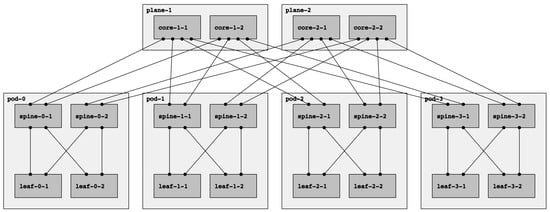
Fat-tree networks are topologically partially ordered graphs and “level” denotes the set of nodes at the same height in such a network. In Figure 1, a fat tree with three levels is depicted. The top-level is called Top of Fabric (ToF) or Core and comprises Core switches. The immediately lower level (aggregation level) is composed of Spine switches. Finally, at level zero (edge level), there are Leaf switches. Let us introduce the concept of Point of Delivery (PoD). A PoD is a subset of a fat-tree network typically containing only Leaf and Spine nodes that are fully interconnected. A node in a PoD communicates with nodes in other PoDs via the ToF.
Figure 1. A fat-tree topology with k=4: four-port switches arranged in four PoDs with four switches each.
The fat-tree topology consists of
k PoDs, numbered left to right from
Pod-0 to
Pod-(k-1), with three layers of switches: leaf switches, spine switches, and core switches. Thus, in a
k PoD fat-tree topology, there are
k switches (each with
k ports) in each PoD arranged in two layers of
k/2 switches, one layer for leaf switches and the other for spine switches. Each leaf switch is connected to
k/2 spine switches. There are
(k/2)2 core switches, each of which connects to
k PoDs. With this topology description, the
k factor can be used to calculate the number of nodes in each level of the fabric.
Table 1 adopted from
[4] summarizes the topological information for a fat tree in terms of the
k factor.
Table 1. Fat-Tree topology summary
[4].
| Number of Pods |
k |
| Core Switches |
(k/2)^2 |
| Spine Switches |
k^2/2 |
| Leaf Switches |
k^2/2 |
| Total Switches |
5k^2/4 |
| Number of Links |
k^3/2 |
Note that there are two types of fat trees: single-plane and multi-plane. In a multi-plane topology (the fat-tree type described above), each ToF node connects to k PoDs. Contrarily, each ToF node connects to every spine node in a single-plane fat tree. With this configuration, even if all ToFs but one are down, the connectivity between leaves is guaranteed. However, it presents a significant drawback: the number of ports needed for each ToF increase significantly, which might be unfeasible if k is too large. In this paper, we will always refer to multi-plane fat-tree topologies, following the notation introduced above and describing the fat-tree in terms of the k factor.
Observe that there are other terminologies for describing fat trees, for example, the one used in the RIFT (Routing In Fat Trees) protocol draft
[5]. That terminology specifies three parameters:
KLEAF, describing the number of ports pointing north or south for the leaf nodes, and
KTOP, which describes the same for the spine nodes. Finally, they denote by
R the redundancy factor, i.e., the number of links from a ToF to a PoD. Following this notation, the topology shown in
Figure 1 can be described as
KLEAF=2,
KTOP=2,
R=1.
Deploying a topology with these properties has certain benefits for the data center. First, all switches are of the same type with the same number of ports, minimizing downtime periods and reducing operating costs (OPEX). Moreover, there are multiple paths between any pair of hosts. In particular, in a k fat-tree topology, there are k/2 paths between two Leaf switches within a pod (intra-pod), and there are k paths between any two Leaf switches that are across pods (inter-pod). This multi-path solution inspires to explore the Equal-cost multi-path routing (ECMP) routing strategy, which allows dividing the fabric traffic load more efficiently.
2. Link-State Routing
Link-state routing protocols, such as OSPF
[6] and IS-IS
[7], have been for many years, and continue to be, the state-of-the-art Interior Gateway Protocols (IGPs) for Internet Service Provider (ISP) backbones. Nevertheless, a link-state routing network protocol cannot easily scale beyond a thousand routers, mainly due to the Link State Advertisements (LSAs) flooding, even though they are hierarchical protocols by design
[8]. Nowadays, data centers can easily accommodate tenths of thousands of servers, which means a few thousand switches/routers. For example, for fifty thousand servers, more than four thousand switches are needed (see the formula in
[4]); more efficient Clos network realizations
[9] claim to demand around 2400 switches for a hundred thousand bare metal servers. In the last several years, the industry and the research community have been working on efficient ways to reduce flooding in this type of protocols; for example, Openfabric is an IS-IS Optimal Distributed Flooding for Dense Topologies
[10].
3. BGP in the Data Center
Among other reasons, the choice of BGP
[11] as a routing protocol for data centers is motivated by (i) the presence of robust implementations, (ii) reduced control plane flooding, (iii) native support for many protocols, such as IPv4 and IPv6, Multiprotocol Label Switching (MPLS), and VPNs, and (iv) multi-path support. BGP was designed for single-path inter-domain routing, and, therefore, it must be specifically configured for multi-path data center routing. Indeed, the dense connectivity of the data center network is vastly different from the relatively sparse connectivity among administrative domains on the Internet. In inter-domain routing, stability is preferred over rapid notification of changes. Therefore, BGP speakers typically hold off sending notifications about changes for a while. Instead, operators want routing updates to be as fast as possible in a data center network. In addition, due to its default behavior as a path-vector protocol, any single link failure can result in a large number of BGP messages passing between all the nodes, a situation that should be avoided in data centers. Finally, by default, BGP speakers build a single best path when a prefix is learned from many different ASes (because they typically represent a separate administrative domain), while in data centers, multiple paths selection is needed. BGP configuration needs to be specifically tailored for the data center. Firstly, eBGP is preferred over iBGP since it is simpler to understand and configure, especially for multi-path support. Secondly, Autonomous System numbering in the data center is different from the traditional one. Only private ASN is used and, to potentially support more than 1024 nodes, the 4-byte ASN address space
[12] is preferred. However, even though the most straightforward approach to ASN assignment is that every router is assigned a different one, this approach leads to the
path hunting problem, which is a variation of the
count-to-infinity problem suffered by distance vector protocols
[13]. To avoid this problem, the practical guideline for ASN assignment in a fat-tree topology is the following: (1) Each Leaf node is assigned a distinct ASN; (2) Spines in the same PoD have the same ASN that is different for each PoD; (3) All ToFs share the same ASN. However, the drawback of this assignment model is that route aggregation is not possible because it can lead to
black-holing. Thirdly, some additional tweaks are needed; that is, the only attribute to consider in the decision process is the AS_PATH, and, in order to support Equal Cost Multi-Path (ECMP), a group of routes for a given destination is considered equal if the AS_PATH length is the same, relaxing the criterion that the ASNs in the AS_PATH should match exactly. Refer to
[14][15] for an in-depth description.
4. RIFT: Routing in Fat Trees
A basic reasoning behind the development of specific routing protocols for the data center is that the awareness of the underlying fat-tree topology may be used as an advantage to reduce control messages flooding. In this regard, given the North–South, East–West orientation, RIFT floods flat link-state information northbound only so that each level obtains the full topology of its South levels. However, link-state information is, with some exceptions, never flooded East–West or back South again. This characteristic defines RIFT as an anisotropic protocol (i.e., the information is not evenly distributed but summarized along the N–S gradient), where the nodes do not receive the same information from multiple directions simultaneously. Indeed, since there is an understanding of the topological dimension, reachability information is not received “freely” on any link. Therefore, under normal conditions, RIFT does not need to tie-break the same reachability information using some kind of distance metric, which leads ultimately to hop-by-hop forwarding to shortest paths only. Moreover, its computation principles (south forwarding direction is always preferred) lead to valley-free forwarding behavior, hence loop-free, allowing nodes to use all feasible paths (i.e., multi-path forwarding), using all the available bandwidth. Consequently, each fabric level obtains the full topology of its South levels and has one default route to the higher level. This allows a highly desirable aggregation of routes but can lead to the black-hole of traffic or even to partial network partitioning in case of misconfiguration or while failures are being resolved. RIFT addresses these problems by implementing an automatic disaggregation of prefixes in case of link and node failures. This mechanism is based on positive non-transitive disaggregation and negative transitive disaggregation. The former is used by a node that detects that its default IP prefix covers one or more prefixes that are reachable through it but not through one or more other nodes at the same level. Thus, it has to advertise those prefixes southbound to prevent traffic black-holing explicitly. It is non-transitive because the effects of this type of disaggregation are always contained in a single level of the fabric. The latter is used by a ToF node when it discovers that it cannot reach a fallen Leaf in a multi-plane topology. Thus, it has to disaggregate all the prefixes of such Leaf, sending them southbound. This type of disaggregation is transitive because if a node receives a negative disaggregation for a specific prefix from its parents, it has to propagate such disaggregation southbound to reach the Leaf. This is necessary since Leaves connected to multiple planes may have to choose the correct plane to prevent traffic black-holing. For details on RIFT mechanism and concepts, such as South Reflection, Flood Repeater, Bandwidth Adjusted Distance, and Thrift packet encoding, please refer to
[5].
5. LSVR: Link State Vector Routing
LSVR aims to overcome the limits of BGP. Indeed, the usage of eBGP avoids using Route Reflectors, requiring a heavy and error-prone manual configuration of peerings; to this end, different peer discovery alternatives have been proposed under the LSVR working group. Moreover, the hop-by-hop nature of the eBGP decision process imposes delays to overall convergence and prevents omniscient views of the fabric. In this regard, LSVR proposes replacing the rule-based BGP decision process with a Shortest Path First algorithm and advocates for using the BGP-LS
[16] extensions for communication with external controllers. At the time of this writing, ongoing LSVR implementations are still unavailable, so LSVR will not be tested. For further information, see
[17].
6. Switching Overlay
In addition to the infrastructure routing use case, migrating Virtual Machines (VM) between different servers keeping their IP addresses unchanged (i.e., maintaining their attachment to a given L3 subnet) is a major requirement from the application point of view, which is completely unaware of the underlying connectivity. It implies that the data center is connected by a transparent layer two fabric, which eventually implements L2 VLANs. Therefore, this requirement demands implementing layer two emulation over layer three environment, using solutions such as VXLAN
[18] or Ethernet Virtual Private Networks (EVPN)
[19].
 +1 credit