Your browser does not fully support modern features. Please upgrade for a smoother experience.
Submitted Successfully!
 +1 credit
Thank you for your contribution! You can also upload a video entry or images related to this topic.
For video creation, please contact our Academic Video Service.
| Version | Summary | Created by | Modification | Content Size | Created at | Operation |
|---|---|---|---|---|---|---|
| 1 | Yan-Bao Guo | + 4785 word(s) | 4785 | 2022-01-25 02:37:28 | | | |
| 2 | Bruce Ren | Meta information modification | 4785 | 2022-01-27 01:50:44 | | |
Video Upload Options
We provide professional Academic Video Service to translate complex research into visually appealing presentations. Would you like to try it?
Cite
If you have any further questions, please contact Encyclopedia Editorial Office.
Guo, Y. Friction Challenge in Hydraulic Fracturing. Encyclopedia. Available online: https://encyclopedia.pub/entry/18831 (accessed on 27 June 2026).
Guo Y. Friction Challenge in Hydraulic Fracturing. Encyclopedia. Available at: https://encyclopedia.pub/entry/18831. Accessed June 27, 2026.
Guo, Yan-Bao. "Friction Challenge in Hydraulic Fracturing" Encyclopedia, https://encyclopedia.pub/entry/18831 (accessed June 27, 2026).
Guo, Y. (2022, January 26). Friction Challenge in Hydraulic Fracturing. In Encyclopedia. https://encyclopedia.pub/entry/18831
Guo, Yan-Bao. "Friction Challenge in Hydraulic Fracturing." Encyclopedia. Web. 26 January, 2022.
Copy Citation
Hydraulic fracturing has become one of the most popular techniques for exploring sustainable energy sources. However, friction is associated with the entire fracturing process, presenting significant challenges for development.
oil and gas
hydraulic fracturing
friction and lubrication
proppant
1. Introduction
Hydraulic fracturing (fracking) is a key process to the exploitation of oil and gas and plays an important role in enhancing oil recovery. It consists of four major processes: downhole pressure-out, fracture formation and extension [1], proppant filling [2], and oil/gas channel formation. For each fracturing process, there exists serious friction challenges to the fracturing machinery.
Fracking not only changes the situation of oil/gas fields but also enhances the production of oil/gas [3][4]. In practical applications, the effects of fracturing are often important indicators to evaluate the maturity of the fracturing. In the last few years, hundreds of fracturing wells [5] have been installed in the oil/gas fields of the China National Petroleum Corporation (CNPC). However, the results were not as expected. It is worth noting that all most of those problems are caused by frictional resistance [6], which leads to insufficient pressure at the bottom of the well, reducing the capacity to form fractures. Therefore, the challenge posed by friction are a foundational and ubiquitous problem in the fracking process.
The use of fracturing fluid imposes a couple side effects. During the formation of rock fractures, it requires breaking down the forces in the rocks formation, by shearing and relative motion, which induce frictional behaviors and energy lose [7]. The fracturing fluid could lubricate and reduce drag, but the proppant filling and propping are still affected by friction, which cause wear and tear. When flowback, the fracturing fluid and proppant of couple are subjected to friction. On one hand, the fluid reacts with the formation to form residuals and filter caking, increasing formation blockage and friction loss. It will cause water sensitivity damage to the formation. On the other hand, the accumulation of proppant particles in the embedded fractures can cause clogging, thereby reducing formation permeability. At the same time, the proppant can erode the formation surface and clamp surface of downhole tool at a certain velocity, causing surface erosion wear. Therefore, the challenge is how to reduce friction during fracturing. Understanding the friction challenges and friction reduction mechanism [8] is the key to improving hydraulic fracturing technology and stimulating innovations, as well as boosting the profit of oil/gas production.
2. Hydraulic Fracturing Basics
Hydraulic fracking is one of the most important technologies for extracting shale oil/gas [9]. Traditionally, fracking injects fracturing fluid with a high viscosity to create a large displacement at the bottom of the well, in order to generate the fracture. Subsequently, high conductive proppant is filled to form non-closed or incomplete closed fractures. Eventually, the mixture of oil/gas flows to the wellhead (Figure 1).
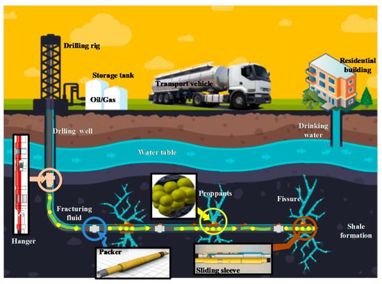
Figure 1. Schematic of the hydraulic fracturing process.
2.1. Mechanism of Hydraulic Fracturing Rock Fracture
Fracking was unsuccessfully tested for the first time in the United Kingdom in 1880s [10]. Decades of research and improvement of the technology made a successful breakthrough in the United States, which has been applied to various fields ever since [11]. In comparison, fracking was studied and applied relatively late in China. Through continuous efforts, the technological gap becomes smaller and smaller; fracking is widely utilized in the oil/gas fields of China.
Fracture formation and extension is the core technology of fracking, which is related to the distribution of in situ stresses, the mechanical properties of rocks, the properties of the fracturing fluid and the proppant properties [12]. According to the Mohr–Coulomb theory, the formation friction is directly related to the formation stress [13], which affects the formation and extension of fractures. When the shear stress of the formation is greater than the tensile stress of the rock, cracks are formed [14]. In general, the stress distribution in the stratum is heterogeneous. At the same time, the inhomogeneity of formation stress will make pressure of the string increase, leading to equipment for high-load work. Hence, during the fracturing process, the homogeneity of the formation stress should be as close to perfection as possible, which not only reduces chances of friction resistance but also improves the fracturing effectiveness.
It is well known that in situ stress is mainly composed of stress from the formation fluid and fracture from the rock skeleton. The direction of the stresses is primarily horizontal and vertical, as shown in Figure 2. There is a horizontal stress shown in Figure 2a. On the other hand, there is a vertical stress shown in Figure 2b,c, in the X and Y directions, respectively. In most cases, the horizontal stress in the fracture is 1–3 times larger than the vertical stress, while the vertical stress is 1.5–3 times larger than the gravitational stress. The crack tips of the formation are destroyed easily, which bring about energy loss and causes fatigue failure in the fracturing equipment. It is important that the proper fracking force be used, and it is a critical factor in the success of technology.
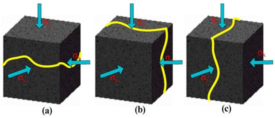
Figure 2. Diagram of crack orientation. (a) Horizontal fracture; (b) vertical fracture in direction σy; (c) vertical fracture in direction σz.
2.1.1. The Mechanism of Fracture Formation
After many years of research and analysis by scholars, the mechanism of the fracture formation by hydraulic fracturing has been well understood. It provides a theoretical basis for hydraulic fracturing tests. Hubberts and Willis [15] established the H-W formation stress prediction model and studied the minimum principal stress perpendicular to the fracture formation. Scott and Williams researched the maximum principal stress of fractures parallel to the formation and further studied the influence of fractures formed in the formation, as well as the fractures of the rock itself. Considering the theory of fracture initiation and elongation under multi-factor conditions, Haimson and Fairhurst [16] built the H-F model and calculated the pressure required for formation of fracture. Eaton et al. [17] set up a model for the relationship between a rock pressure’s gradient and formation depth, for which they used the formation stress coefficient and formation Poisson’s ratio to perfect the model. Anderson considered the influence of the formation stress concentration and referred to optimize the H-W model. Bradley [18] analyzed the relationship between shear stress and wall cracks, which demonstrated that shear force is the decisive factor in the formation of cracks. Yew et al. [19] utilized a three-dimensional elastic model to describe the impact of stress distribution around the wellbore on the fractures. Fallahzadeh [20] studied the influence of the stress distribution around the casing and cementing sheath around the fractures. Lv et al. [21] established a mathematical model for determining crack pressures based on the elastic mechanics theory. Therefore, in order to obtain effective fracture germination for hydraulic fracturing, it is necessary to overcome the friction between rock layers. Moreover, to avoid friction between rock layers, we need further carry out fracturing fluid lubrication.
2.1.2. The Mechanism of Fracture Extension
Fracture extension refers to the extension and expansion of the fracture, which signifies the expansion of the high-pressure region to the low-pressure region and increases the effective area of the fracture. The extending direction is always perpendicular to the direction of the minimum principal stress, which is influenced by the lithology of the rock formation [22][23], the rock’s fracture surface, and natural fractures. According to the linear elastic fracture mechanics model, the fracture stress and strain field at the top of the seam are proportional to the stress intensity factor. Anderson [24] thought that rock strength was the main factor affecting fracture extension from high strength to low strength. Warpinski [25] studied the laws of hydraulic and natural fractures to analyze the mechanism of crack fracture. In doing so, he calculated the extension direction of hydraulic fractures. Martin [26] researched the process of the fracture formation in soft rocks, deriving the mathematical formula for the opening threshold of cracks on the plastic fracture surface. In brief, the friction of the formation causes different degrees of fracking slips, which are horizontal slips and shear slips. It is in facing the challenge of friction on the rock surface that the formation of cracks requires fluid lubrication, which makes it easy to form cracks.
Fracture formation and extension are significant steps in the fracturing process, which are deeply influenced by downhole friction, fracture fluid filling [27], and proppant propping [28]. The greater the friction, the more difficult it is to crack and extend. However, the high viscosity of fracturing fluids can transfer energy to the formation and extension of cracks. Fracturing fluids carry proppant and maintain conductivity. The high viscosity fracturing fluids can compensate for the energy dissipation during fracturing and form rock crevices and extensions. Meanwhile, high-strength proppants sustain the crack, so that it does not close. However, low intensity proppant is more likely to flowback and accumulate, and crack extension is more difficult.
2.2. Hydraulic Fracturing Fluid
Fracturing fluid [27][29] is a high viscosity fluid, which plays a role in lubrication and transportation during fracturing. Common examples include water-based [30], oil-based [31], emulsified, foam [32][33][34][35], alcohol-based [36][37][38][39] acid-based fracturing fluids, and so on. The most widely used is a water-based fracturing fluid [36], which is shown in Figure 3.
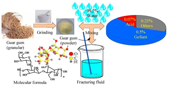
Figure 3. Diagram of the water-based fracturing fluid.
Water is mainly used in fracturing fluids [30] as the dispersion medium. It needs to add water-soluble polymers and various reagents (thickening agents [40], cross-linking agents [41], and gel breaking agents [42] to form the working fluid required for the process. Water accounts for 99.2% of the weight percentage. The processing is safe, reliable, and has low production costs. When compared to oil-based and foam fracturing fluids, the friction resistance of water-based fracturing fluids is lower. Under atmospheric pressure, the fluid is controlled easily, due to the high hydrostatic pressure of water-based fracturing fluid.
Water-based fracturing fluid consists of many additives, including thickening agents [40], cross-linking agents [41][43], and gel breaking agents [42]. So, the first step involves adding thickening agents, mainly to increase the viscosity, reduce its filtration performance, reduce its frictional loss, and improve the carrying capacity. The cross-linking agents can fuse with thickening agents to improve the proppant carrying capacity and reservoir permeability. After the gel breaking are added, these agents mainly reduce the viscosity of the crosslinking agent to ensure the dredging ability of the crack and reduce the damage of reservoir. Finally, these fracturing reagents need to be recycled back to reduce the permeability loss to the reservoir. The classification of thickening agents, cross-linking agents, and gel breaking agents are shown in Table 1.
According to the apparent viscosity theory [44], the viscosity of a fracturing fluid is an important factor effecting the friction. However, viscosity has two effects on friction. On one hand, it can increase the shear stress between the fluid and the pipe wall, leading to an increase of friction losses. On the other hand, with the increase of the viscosity, the polymer solution produces a transition delay effect, which inhibits turbulence and reduces friction loss.
Table 1. Classification of main additives for water-based fracturing fluids.
| Type of Additives | Classification of Additives | Features | Case | References |
|---|---|---|---|---|
| Thickeners | Vegetable gum and its derivatives | Strong thickening ability, low price, poor temperature resistance, and large residue content | Guanidine gum, sesbania gum, and coumarin gum | [45][46] |
| Cellulose and its derivatives | Good sand suspension, low filtration loss, high thermal stability, and high cost | Carboxymethyl cellulose, hydroxyethylcellulose, and carboxymethyl hydroxyethyl cellulose | [47][48][49] | |
| Synthetic polymer fracturing fluid | Good gel stability, strong sand suspending ability, and less formation damage | AA, AM, and NFT | [50][51] | |
| Cross-linking agent | Boron cross-linking agent | Better delayed cross-linking and high-temperature resistance | Inorganic boron/organic boron cross-linking agent | [46][52][53][54] |
| Transition metal cross-linking agent | Higher cross-linking efficiency, less damage to the reservoir, lower cost, and poor shear resistance | Ti4+/Zr4+ cross-linking agent | [55] | |
| Composite cross-linking agent | High shear performance and good temperature resistance | YM-A | [56][57] | |
| Nano cross-linking agent | Improve the cross-linking efficiency, reduce the dosage of thickening agents, and save the cost. | ZrO2/TiO2 cross-linking agent | [58][59][60] | |
| Gel breakers | Acid gel breaker | Low damage to reservoir permeability | HJD-W | [61][62] |
| Enzymatic gel breaker | Specificity and green environmental protection | β-Mannanase | [55][63] | |
| Oxidized gel breaker | Easy to flow back, low price, and high breaking efficiency | Ammonium persulfate and Potassium persulfate | [64] |
Controlling the fluid’s viscosity becomes the key to reducing friction losses (which have an important role in reducing the suspended sand), fluid friction, and filtration loss. During the pumping stage, the fluid viscosity needs to be moderated to achieve a state of suspended sand and low friction. During the fracture formation stage, the fracturing fluid viscosity needs to increase. The increased fracturing fluid has enough fluid pressure to complete the expansion [65] and extension of fractures. During the drainage stage, the fluid viscosity needs to be reduced. A low viscosity fluid can flow back to avoid blockage collapse of the stratigraphic structures.
2.3. Hydraulic Fracturing Proppant
Fracturing proppant is an indispensable filler in the fracking process. The proppant [9] supports fractures and prevents their closure by forming a highly dredging oil/gas flow channel. The proppant type and particle characteristics (i.e., size, strength, sphericity, and roundness) determine the flow conductivity of the fractures. The stronger the flow conductivity, the higher the oil/gas production capacity. However, based on the fitting formula theory, the proppant particle size and ratio to sand have an impact on the friction. This causes abrasion near the well and sand blockages in the crack.
In the fracturing process, ideal proppants (Figure 4) have high compressive strengths and a small crushing rate. Most proppants are spherical particles with uniform size [65] and smooth surface, which are easy to transport in fracturing fluid. When the proppant supports the fracture, it does not react with the formation fluid. The origin of the proppant is river sand, which comes from the Arkansas River in the United States. Until the mid-1950s, natural quartz sand [66], which is shown in Figure 4a, was widely used in fracking. After a few decades, ceramic proppants [67][68] were utilized in the fracturing process. Ceramic proppants have the advantages of having high strength, as well as good corrosion resistance and roundness. From the 1980s till now, coated [69], biological, and self-suspending proppants continue to improve proppant performance [70]. Propant transportation schedule is shown in Figure 4.
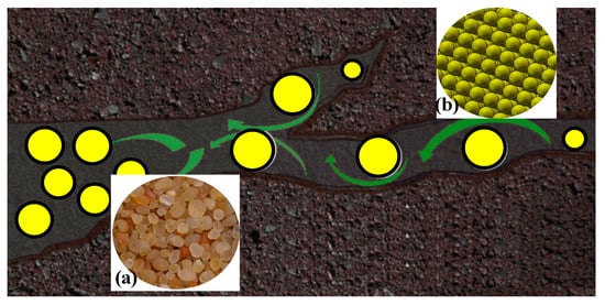
Figure 4. Diagram of hydraulic fracturing proppant. (a) natural quartz sand; (b) proppant.
Proppants are carried by the fracturing fluids, also known as sand-carrying fluids. The fluids are transported to the formation, via coiled tubing, in order to realize the fracturing operation. Unfortunately, walls of coiled tubing suffer from proppant erosion and wear, causing the structure to fail. In line with Dean’s theory [71], the flow rate and viscosity of the fluids correlate with the degree of erosion and wear. As the flow rate and viscosity of the fluid increases, the erosive and wear of the tubing increases. During the conveying process, the roller will produce centrifugal forces on the fluid. Under the centrifugal force, the fluid will rotate and float and can increase the friction of the tubing. Therefore, researchers pay close attention to the friction and erosion of proppants. Carpenter proposed that new proppants [72] need to reduce the concentration of the fluid, in order to reduce friction and erosion of proppants.
3. Friction Mechanism in Hydraulic Fracturing (Problem)
The impacts of friction in hydraulic fracturing cannot be ignored. Researchers began to pay the attention to the friction problem in the 1980s. Excessive friction will cause serious pressure loss in the fracturing process, leading to increase the risk in the fracturing construction. Friction loss in the process is mainly composed of two parts: the friction along the path and near the wellbore.
3.1. Friction along the Path
Installing coiled tubing is one of the vital steps in the fracturing process. During the process, the coiled tubing comes into contact with the borehole wall, resulting in frictional resistance along the path. Friction loses becomes more serious as the depth of tubing increases. The main factors affecting the friction along the path is the coiled tubing diameter, fracturing fluid viscosity, and proppant concentration.
3.1.1. Coiled Tubing Friction
Coiled tubing is required to be installed to a depth of more than seven kilometers. As the depth increases, the tubing starts to act like a soft rope in the borewell. As a result, experts build soft rope models to analyze the tubing stress. Wojtanowicz et al. [73] studied the effects of a borehole’s friction on the tubing’s stress, in which the high friction in the wellbore leads to a stress concentration in the tubing, resulting in structural failure of the tubing and thread seal on the casing. In 1983, Johancsik et al. [74] first performed a stress analysis on the tubing and established the micro-element soft rod for structural mechanics model. Sheppard et al. [75] considered friction and torque factors when designing and optimizing a borehole’s trajectory. Based on the Sheppard model, Maida’s team [76] considered the effect of viscous resistance of a fluid on the friction of the tubing. Daring et al. [77] established a two-dimensional model to analyze the deformation of the tubing in the wellbore. His team [78] built a three-dimensional model to analyze the force on the tubing in the wellbore. In conclusion, the increase of tubing depth and friction along the pipeline is a problem that cannot be ignored. In order to further alleviate the oil and gas pipeline’s structural wear, the main way to prevent damage during drilling is to reduce friction with lubrication.
During the process of tubing friction and wear, the coefficient of friction (COF) also becomes a crucial factor to determine the stability and reliability of the tubing. Ho et al. [79] considered the effect of large deformations on the COF of the borehole. Sheppard used theoretical models to research the influence of borehole geometry on frictional resistance. Dikken et al. [80] introduced the effect of pressure gradient along the borehole on the COF. Landman and Goldthorpe [81] studied the relationship between uniform flow and the COF, which established the relevant prediction model. Johancsik et al. [74][82] investigated the effects of the type of mud and wellbore conditions on friction coefficients. When researching the influence of the COF on pipeline wear, not only should the sliding friction be considered but also the comprehensive friction, including drilling fluid lubrication and rock properties. Therefore, the COF usual empirical value is summarized in Table 2. The data in Table 2 are derived from the measured calculation in the study of the friction coefficient of the string in a large displacement well.
Table 2. Value of borehole friction coefficient (COF).
| Drilling Fluid System | COF in a Casing | COF in the Naked Eye |
|---|---|---|
| Water-based drilling fluid | 0.24 | 0.29 |
| Oil-based drilling fluid | 0.17 | 0.21 |
| Brine drilling fluid | 0.30 | 0.30 |
3.1.2. Fracturing Fluid Viscosity
After the fracturing fluid enters the formation, the balance of forces in the formation breaks, causing different degrees of shearing damage and energy loss in the formation. The losses are mainly caused by water damage and water sensitivity damage and are related to the fluid’s viscosity. At certain locations of the pipe the friction becomes severe.
Water damage of the fracturing fluids mainly occurs in low permeability reservoirs. Some water is locked in the formation, due to the low permeability and poor porosity of the formation; as a result, this causes water damage in the formation. Water damage can lead to an increase in the viscosity of the fluid and, as a result, the friction resistance increases within the well. Bahrami et al. [83] studied the mechanism of water lock damage, in order to analyze the factors of increasing viscosity. Ni’s team [84] used nuclear magnetic resonance to research the water damage in coal seams. They proposed protective measures for surfactants, in order to reduce the viscosity. Fan et al. [85] invented a waterproof sealing agent, used to reduce water damage and decrease the viscosity of the fluid. Bijeljic’s team [86] utilized the multi-component porosity model to analyze the effects of water damage on multiphase oil/gas. Holditch et al. [87] used the capillary pressure changes of tight sandstone formations to study the combined effects of hydraulic fracturing intrusive formation permeability damage and relative permeability damage The greater the pressure, the more severe the water lock damage. Lin et al. [88] used a combination of experimental and numerical simulations to research the influence of water lock damage on formations. Therefore, the phenomenon of water lock damage is a non-negligible phenomenon that causes shale formation damage. To a certain extent, water lock damage leads to increased formation pressure. The inner surface of downhole devices and pipelines are eroded and worn down by proppant particles, resulting in surface stress concentrations. Under the comprehensive stress caused by the pressure of the medium in the pipe, as well as other external forces, it is feasible to form cracks and expand, which can eventually lead to the collapse of an oil and gas pipeline. In order to mitigate this damage, the main measures focus on effectively reducing the viscosity of the fluid and friction between downhole devices, pipes, and borehole walls.
Besides water lock damage, water sensitivity damage can also cause damage in the formation. Water sensitivity damage is caused by the chemical reactions between the fracturing fluid and minerals in the formation. This causes erosion of the formation, which causes the particles in the formation to fall off, accumulate, and increase the tubing friction along the path. Researchers began to focus on this type of damage in the 1930s. Monaghan et al. [89] studied the interactions between the aqueous phase and clay minerals in the reservoir. They found that water-sensitive damage was severe, but the reservoir permeability decreased. Mungan et al. [90] analyzed the fluid’s pH and salinity when the reservoirs were damaged. Tchistiakov et al. [91] investigated the water sensitivity damage of the charged particles around clay. Aradeiba et al. [73] researched the water sensitivity damage of strata without expansive clay minerals. However, the impact of water sensitivity damage on the formation was not great. Effective prevention and protection can decrease the friction along the path and, as a result, reduce the impact of the water sensitivity damage on the formation.
3.1.3. Proppant Concentration
Proppant, like the Great Wall, supports cracks formed by the fracturing fluid. The ability to embed and accumulate proppant particles can damage the original formation structure, resulting in erosive wear and different degrees of friction in the cracks [92]. Holditch et al. [93] studied the effects of different concentrations of proppant in the deep well formation. They determined that the higher the concentration, the more serious the erosion wear. Lacy’s team [94] established a proppant embedment model to research the relationship between the depth of proppant embedment and degree of formation damage under different formation rocks. Cook et al. [95] investigated the relationship between fluid viscosity and the depth in which the proppant embedded itself within complex formations. Using the shunt loading method, Penny et al. [96] studied the formation damage caused by proppants. Therefore, it is inevitable that proppant embedment will cause damage within the formation, resulting in erosion and wear of the formation and equipment. This is a problem that should be avoided and prevented.
Failure caused by the wear of the downhole device, pipeline surface, and accumulation of metal particles in the pipeline caused the blockage in the formation. Blockage can cause local formation pressure to be too high and is the main way to erode and destroy the formations. In the process of proppant filling cracks, the movement of fluid assists proppants with large diameters to fill the cracks, and some proppants with small diameters will also accumulate and block. Subsequently, the pressure and friction in the bottom of the well would increase. In the oil-loosened sandstone formation, Wong et al. [97] found that proppants are easy to accumulate after the sandstone particles fall off the multi-layer formation skeleton and damage the formation. Carroll et al.’s [58] research found that broken proppants would block the crack even more, reducing its permeability. However, in the clay mineral formation, the clay would set off the hydration and expansion reaction. Hayatdavoudi et al.’s [98] research showed that after the reaction, proppants block the cracks, thereby increasing the friction along the cracks. Khilar and Fogler [99] studied the friction loss of salt chemical proppants to the formations. Civan et al. [100] established the mathematical model of clay hydration expansion, finding that more serious clay hydration would have more proppant accumulation and, therefore, more frictional losses in the formation. The damage mechanism of the proppant is shown in Figure 5. When the proppant first accumulates in the crack (as shown in the figure with a II), and when the proppant breaks, the proppant accumulates again (shown in the figure as part I). To reduce the accumulation of the proppant in the crack, researchers have proposed a mechanism study of the surface modifications of the proppant.
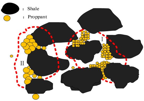
Figure 5. Friction and damage mechanism of the proppant. (I) second proppant accumulation; (II) first proppant accumulation.
3.2. Friction near Wellbore
During hydraulic fracturing, the fluid enters the cracks of the formation from the pump through surface lines, coiled tubing, and perforation holes. The whole process is influenced by frictional resistance, leading to pressure loss. Excessive friction causes crack length to grow, resulting in serious sand plugging. In the 1980s, near-wellbore friction refers to the concentration of stress around the perforations and wellbore, which caused near-well friction. Near-well friction is mainly divided into perforation friction and fracture bending friction.
3.2.1. Perforation Friction
During the fracturing process, an insufficient number of perforations and perforation pollution will give rise to perforate friction and occur in the perforation hole. The schematic diagram of perforation abrasion is shown in Figure 6. It can be seen from Figure 6 that the number of perforations is insufficient; as the perforation resistance increases, proppant will settle faster, leading to blockages. Economides and Nolte [101] showed from reservoir stimulations that friction causes pressure loss. Daneshy et al. [102][103] performed simulations on perforation fractures and found physical relationships between perforation friction and the number of perforations. After that, Crump and Conway [104] established the friction model for hole perforations and discovered that different perforation parameters generated different perforation friction types. Cramer et al. [105] found a linear relationship between the hole’s diameter and amount of proppant passing through the hole. Wu’s team [106][107] analyzed the effects of the size of the diameter, as well as the effect that the number of perforations had, with regard to friction. Lecampion et al. [108][109] showed that pressure drop would cause friction from the perforations to decrease. El-Rabaa and Shah [110] established a mathematical model of the perforation friction on the hole. This model showed that an insufficient number of perforations will cause an increase in friction. Therefore, in hydraulic fracturing, the ideal case is to maintain the number of perforations within a reasonable range.
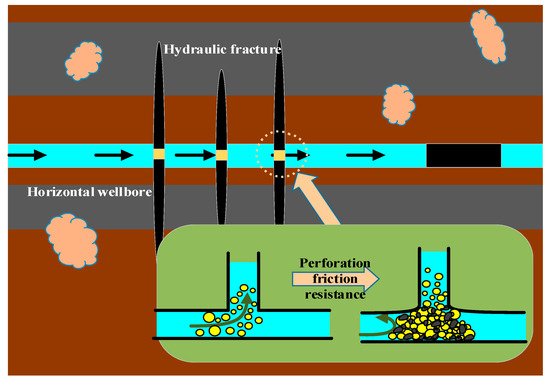
Figure 6. The schematic diagram of perforation abrasion.
When the number of perforations is insufficient, the friction (as a result of perforations) is larger, resulting in a lower fracturing rate, in which the solid particles of proppant flushed the surface of the perforation, causing serious erosive wear of the surface of the perforation. Meanwhile, erosive wear can also generate perforation pollution, which is the main cause of perforation wear. Long’s team established a perforation wear model to explore the effect of perforation wear on crack propagation.
3.2.2. Fracture Bending Friction
The friction caused by bend after a fracture is another friction mechanism near the well. In hydraulic fracturing engineering, bending friction is mainly caused by inclination, the number of fractures, an improper perforation stage, and other factors. Zhu’s team [111] established a dynamic frictional torque model for large, deviated wells, in order to study the influence of inclination of friction resistance on oil/gas well. They determined that the higher the inclination, the greater the friction wear. According to the Besilianke formula, a mathematical model of friction is built and can be used to more easily analyze the influence of the inclination on the friction coefficient [112]. All in all, we need to further consider the influence of wellbore inclination and friction. In order to reduce the corresponding frictional resistance, it is necessary for us to reasonably reduce the wellbore inclination.
On the other hand, multiple cracks are a factor that effect the bending friction from fracture. Multiple cracks, caused by the improper phase of natural fractures and perforations, can result in the increase of bending friction in near-well friction. Overbuy et al. [113] confirmed the existence of multiple cracks. Lyle et al. [114] discussed the causes of multiple cracks. According to Michael’s theory, the fracture bending friction is related to the total displacement of the fracturing fluid [115]. McDaniel at al. [116], Brumley et al. [117], and Mahrer et al. [118] observed multi-crack morphology and found that the greater frictional resistance, the more serious the damage of the construction. Lu studied the relationship between the crack width and severity of wear (due to friction). Using a numerical model, Jeffrey et al. [119] proved that the formation pressure of the second crack was 7% higher than that of the first crack. As a result, how many cracks would be reasonable is known. More cracks mean more pressure drops and a more serious friction wear at the formation.
References
- Zhang, R.; Hou, B.; Zeng, Y.; Zhou, J.; Li, Q. Investigation on Hydraulic Fracture Initiation and Propagation with LPG Fracturing in Shale Formation based on True Tri-Axial Laboratory Experiments. In Proceedings of the IADC/SPE Asia Pacific Drilling Technology Conference and Exhibition, Bangkok, Thailand, 27–29 August 2018.
- Parker, M.A.; Ramurthy, K.; Sanchez, P.W. New Proppant for Hydraulic Fracturing Improves Well Performance and Decreases Environmental Impact of Hydraulic Fracturing Operations. In Proceedings of the SPE Eastern Regional Meeting, Lexington, KY, USA, 3–5 October 2012.
- Al-Dhamen, M.; Makmun, A.; Hilal, A. Production Optimisation with Hydraulic Fracturing: Application of Fluid Technology to Control Fracture Height Growth in Deep Hard Rock Formation. In Proceedings of the International Petroleum Technology Conference, Beijing, China, 26–28 March 2013.
- Williams, V.; McCartney, E.; Nino-Penaloza, A. Far-Field Diversion in Hydraulic Fracturing and Acid Fracturing: Using Solid Particulates to Improve Stimulation Efficiency. In Proceedings of the SPE Asia Pacific Hydraulic Fracturing Conference, Beijing, China, 24–26 August 2016.
- An, M.; Zhang, F.; Chen, Z.; Elsworth, D.; Chris, M. Mineralogy-Controlled Frictional and Stability Properties of Longmaxi Shale: Implications for Hydraulic Fracturing Induced Seismicity. In Proceedings of the 5th ISRM Young Scholars’ Symposium on Rock Mechanics and International Symposium on Rock Engineering for Innovative Future, Okinawa, Japan, 1–4 December 2019.
- Wang, J.; Yao, E.; Qiu, Y.; Zhou, F.; Wang, Z.; Zhang, L.; Rui, W. Research and Evaluation of a Novel Low Friction, High Density and High Temperature Resistance Fracturing Fluids System. In Proceedings of the 53rd U.S. Rock Mechanics/Geomechanics Symposium, New York, NY, USA, 23–26 June 2019.
- Zhang, X.; Jeffrey, R.G. Hydraulic fracture propagation across frictional interfaces. In Proceedings of the Paper presented at the 1st Canada—U.S. Rock Mechanics Symposium, Vancouver, BC, Canada, 27–31 May 2007.
- Khan, S.; Shen, L.; Everson, N. Engineered Friction Reducers Enhance Proppant Transport; A Hart Energy Publication; E & P: Singapore, 2018; Volume 1, pp. 68–71.
- Xie, L.; Min, K.B.; Shen, B. Simulation of hydraulic fracturing and its interactions with a pre-existing fracture using displacement discontinuity method. J. Nat. Gas Sci. Eng. 2016, 36, 1284–1294.
- Mair, R.; Bickle, M.; Goodman, D.; Koppelman, B.; Roberts, J.; Selley, R.; Shipton, Z.; Thomas, H.; Walker, A.; Woods, E.; et al. Shale Gas Extraction in the UK: A Review of Hydraulic Fracturing; Royal Society and Royal Academy of Engineering: London, UK, 2012; pp. 9–59.
- Smith, M.B.; Miller, W.K.; Haga, J. Tip screenout fracturing: A technique for soft, unstable formations. SPE Prod. Eng. 1987, 2, 95–103.
- Shlyapobersky, J.; Chudnovsky, A. Review of recent developments in fracture mechanics with petroleum engineering applications. In Proceedings of the Rock Mechanics in Petroleum Engineering, Delft, The Netherlands, 29–31 August 1994.
- Huang, J.; Morris, J.P.; Fu, P.; Settgast, R.R.; Sherman, C.S.; Ryerson, F.J. Hydraulic-fracture-height growth under the combined influence of stress barriers and natural fractures. SPE J. 2019, 24, 302–318.
- Dam, D.B.V.; Pater, C.J.D. Roughness of Hydraulic Fractures: The Importance of In-Situ Stress and Tip Processes. SPE J. 2013, 6, 4–13.
- Hubbert, M.K.; Willis, D.G.W. Mechanics of hydraulic fracturing. Trans. AIME 1972, 18, 369–390.
- Haimson, B.; Fairhurst, C. In-Situ Stress Determination at Great Depth by Means of Hydraulic Fracturing. Rock Mechanics—Theory and Practice. In Proceedings of the 11th Symposium on Rock Mechanics, Berkeley, CA, USA, 16–19 June 1969; pp. 559–584.
- Eaton, B. Fracture Gradient Prediction and Its Application in Oilfield Operations. J. Pet. Technol. 1969, 21, 1353–1360.
- Bradley, W.B. Failure of Inclined Boreholes. J. Energy Resour. Technol. 1979, 101, 232–239.
- Yew, C.H.; Li, Y. Fracturing of a Deviated Well. SPE Prod. Eng. 1988, 3, 429–437.
- Fallahzadeh, S.A.H.; Shadizadeh, R.S.; Pourafshary, P. Dealing with the Challenges of Hydraulic Fracture Initiation in Deviated-Cased Perforated Boreholes. In Proceedings of the Trinidad and Tobago Energy Resources Conference, Port of Spain, Trinidad, 27–30 June 2010.
- Lv, Z.; He, S.; Gu, D.; Zhang, H. Hydraulic fracture initiation while staged fracturing for horizontal wells. In Proceedings of the IPTC 2013: International Petroleum Technology Conference, European Association of Geoscientists & Engineers, Beijing, China, 26–28 March 2013. Cp-350–00067.
- Van Dam, D.B.; Papanastasiou, P.; De Pater, C.J. Impact of Rock Plasticity on Hydraulic Fracture Propagation and Closure. SPE Prod. Facil. 2000, 17, 149–159.
- Schmidt, R.A.; Rossmanith, H.P. Basics of rock fracture mechanics. In Rock Fracture Mechanics; Springer: Vienna, Austria, 1983; pp. 1–29.
- Anderson, G.D. Effects of friction on hydraulic fracture growth near unbonded interfaces in rocks. Soc. Pet. Eng. J. 1981, 21, 21–29.
- Warpinski, N.R.; Teufel, L.W. Influence of geologic discontinuities on hydraulic fracture propagation (includes associated papers 17011 and 17074). J. Pet. Technol. 1987, 39, 209–220.
- Martin, A.N. Crack tip plasticity: A different approach to modelling fracture propagation in soft formations. In Proceedings of the SPE Annual Technical Conference and Exhibition, Dallas, TX, USA, 1–4 October 2000.
- Barati, R.; Liang, J.T. A review of fracturing fluid systems used for hydraulic fracturing of oil and gas wells. J. Appl. Polym. Sci. 2014, 131, 318–323.
- Liang, F.; Sayed, M.; Al-Muntasheri, G.A.; Chang, F.F.; Li, L. A comprehensive review on proppant technologies. Petroleum 2016, 2, 26–39.
- Montgomery, C. Fracturing fluids. In Proceedings of the ISRM International Conference for Effective and Sustainable Hydraulic Fracturing, Brisbane, Australia, 20–22 May 2013.
- Oprea, S. Effects of guar gum content on structure and properties of multi-crosslinked polyurethane composite films. Compos. Part B Eng. 2013, 44, 76–83.
- Mao, J.; Wang, D.; Yang, X.; Zhang, Z.; Zhang, Y.; Zhao, J. Experimental study on high temperature resistance aluminum-crosslinked non-aqueous fracturing fluids. J. Mol. Liq. 2018, 258, 202–210.
- Sun, X.; Liang, X.; Wang, S.; Lu, Y. Experimental study on the rheology of CO2 viscoelastic surfactant foam fracturing fluid. J. Pet. Sci. Eng. 2014, 119, 104–111.
- Li, C.; Huang, Y.; Sun, X.; Gao, R.; Zeng, F.; Tontiwachwuthikulac, P.; Liang, Z. Rheological properties study of foam fracturing fluid using CO2 and surfactant. Chem. Eng. Sci. 2017, 170, 720–730.
- Harris, P.C.; Haynes, R.J.; Egger, J.P. The Use of CO2-Based Fracturing Fluids in the Red Fork Formation in the Anadarko Basin, Oklahoma. J. Pet. Technol. 1984, 36, 1003–1008.
- Reynolds, M.M.; Bachman, R.C.; Peters, W.E. A comparison of the effectiveness of various fracture fluid systems used in multistage fractured horizontal wells: Montney Formation, unconventional gas. In Proceedings of the SPE Hydraulic Fracturing Technology Conference, The Woodlands, TX, USA, 4–6 February 2014.
- Alharthy, N.; Teklu, T.W.; Kazemi, H.; Graves, R.; Hawthorne, S.; Braunberger, J.; Basak, K. Enhanced oil recovery in liquid-rich shale reservoirs: Laboratory to field. SPE Reserv. Eval. Eng. 2018, 21, 137–159.
- Wang, L.; Yao, B.; Cha, M.; Alqahtani, N.B.; Patterson, T.W.; Kneafsey, T.J.; Jennifer, L.; Miskimins, J.L.; Yin, X.; Wua, Y. Waterless fracturing technologies for unconventional reservoirs-opportunities for liquid nitrogen. J. Nat. Gas Sci. Eng. 2016, 35, 160–174.
- Grundmann, S.R.; Rodvelt, G.D.; Dials, G.A.; Robert, E.A. Cryogenic nitrogen as a hydraulic fracturing fluid in the devonian shale. In Proceedings of the SPE Eastern Regional Meeting, Pittsburgh, PA, USA, 9–11 November 1998.
- Rogala, A.; Krzysiek, J.; Bernaciak, M.; Hupka, J. Non-aqueous fracturing technologies for shale gas recovery. Physicochem. Probl. Miner. Processing 2013, 49, 313–322.
- Elloy, F.C.; Teel, A.L.; Watts, R.J. Activation of persulfate by surfactants under acidic and basic conditions. Groundw. Monit. Remediat. 2014, 34, 51–59.
- Ghanbari, E.; Dehghanpour, H. The fate of fracturing water: A field and simulation study. Fuel 2016, 163, 282–294.
- Malone, M.R.; Nelson, S.G.; Jackson, R. Enzyme breaker technology increases production, Grayburg-Jackson field, southeast new Mexico: A case history. Paper presented at the SPE Permian Basin Oil and Gas Recovery Conference, Midland, TX, USA, 21–23 March 2000.
- Churakov, A.V.; Pichugin, M.N.; Fayzullin, I.G.; Gainetdinov, R.R.; Makarevich, S.B.; Mikhaylov, D.Y.; Williams, B.; Thomas, H. Non-Guar Synthetic Hydraulic Fracturing Gels–Successful Concept of Choice. In Proceedings of the SPE Russian Petroleum Technology Conference, Virtual, 26–29 October 2020.
- Edwards, M.F.; Smith, R. The turbulent flow of non-Newtonian fluids in the absence of anomalous wall effects. J. Non-Newton. Fluid Mech. 1980, 7, 77–90.
- Goel, N.; Shah, S.N.; Yuan, W.L.; O’Rear, E.A. Suspension characteristics of borate-crosslinked gels: Rheology and atomic force microscopy measurements. J. Appl. Polym. Sci. 2001, 82, 2978–2990.
- Bishop, M.; Shahid, N.; Yang, J.; Barron, A.R. Determination of the mode and efficacy of the cross-linking of guar by borate using MAS 11B NMR of borate cross-linked guar in combination with solution 11B NMR of model systems. Dalton Trans. 2004, 2621–2634.
- Vollmer, D.P.; Alleman, D.J. HEC no longer the preferred polymer. In Proceedings of the SPE International Symposium on Oilfield Chemistry, Houston, TX, USA, 13–16 February 2001.
- Prado, H.J.; Matulewicz, M.C. Cationization of polysaccharides: A path to greener derivatives with many industrial applications. Eur. Polym. J. 2014, 52, 53–75.
- Cao, X.; Sun, S.; Peng, X.; Zhong, L.; Sun, R. Synthesis and characterization of cyanoethyl hemicelluloses and their hydrated products. Cellulose 2013, 20, 291–301.
- Zhang, Y.; Mao, J.; Zhao, J.; Yang, X.; Zhang, Z.; Yang, B.; Zhang, W.; Zhang, H. Preparation of a novel ultra-high temperature low-damage fracturing fluid system using dynamic crosslinking strategy. Chem. Eng. J. 2018, 354, 913–921.
- Mao, J.; Tan, H.; Yang, B.; Zhang, W.; Yang, X.; Yang, Z.; Zhang, H. Novel hydrophobic associating polymer with good salt tolerance. Polymers 2018, 10, 849.
- Sun, H.; Qu, Q. High-efficiency boron crosslinkers for low-polymer fracturing fluids. In Proceedings of the SPE International Symposium on Oilfield Chemistry, The Woodlands, TX, USA, 11–13 April 2011.
- Brannon, H.D.; Ault, M.G. New, delayed borate-crosslinked fluid provides improved fracture conductivity in high-temperature applications. In Proceedings of the SPE Annual Technical Conference and Exhibition, Dallas, TX, USA, 6–9 October 1991.
- Legemah, M.; Guerin, M.; Sun, H.; Qu, Q. Novel high-efficiency boron crosslinkers for low-polymer-loading fracturing fluids. SPE J. 2014, 19, 737–743.
- Kalgaonkar, R.A.; Patil, P.R. Performance enhancements in metal-crosslinked fracturing fluids. In Proceedings of the North Africa Technical Conference and Exhibition, Cairo, Egypt, 20–22 February 2012.
- Williams, D.A. Crosslinker Composition for High Temperature Hydraulic Fracturing Fluids. U.S. Patent 4534870, 13 August 1985.
- Hodge, R.M. Method of Fracturing a Subterranean Formation Using Delayed Crosslinker Compositions Containing Organic Titanium Complexes. U.S. Patent 4657080, 14 April 1987.
- Al-Muntasheri, G.A.; Liang, F.; Hull, K.L. Nanoparticle-enhanced hydraulic-fracturing fluids: A review. SPE Prod. Oper. 2017, 32, 186–195.
- Hurnaus, T.; Plank, J. Behavior of titania nanoparticles in cross-linking hydroxypropyl guar used in hydraulic fracturing fluids for oil recovery. Energy Fuels 2015, 29, 3601–3608.
- Chen, F.; Yang, Y.; He, J.; Bu, T.; He, X.; He, K.; Xiang, C.; Yu, Z.; Wu, H. The gelation of hydroxypropyl guar gum by nano-ZrO2. Polym. Adv. Technol. 2018, 29, 587–593.
- Dawson, J.C.; Le, H.V.; Cramer, D. Successful application of a novel fracturing fluid in the wasatch formation in eastern. In Proceedings of the SPE Annual Technical Conference and Exhibition, New Orleans, LA, USA, 27–30 September 1998.
- Norman, L.R. Properties and early field results of a liquid gelling agent for acid. In Proceedings of the SPE Production Technology Symposium, Hobbs, NM, USA, 30–31 October 1978.
- Beadle, B.M.; Baase, W.A.; Wilson, D.B.; Gilkes, N.R.; Shoichet, B.K. Comparing the thermodynamic stabilities of a related thermophilic and mesophilic enzyme. Biochemistry 1999, 38, 2570–2576.
- Gong, Y.; Lei, Y.; Chen, X.; Song, H.; Liu, R. A novel silica aerogel microspheres loaded with ammonium persulfate gel breaker for mid-deep reservoirs. J. Sol-Gel Sci. Technol. 2018, 88, 105–113.
- Carroll, H.B., Jr.; Baker, B.A. Particle size distributions generated by crushed proppants and their effects on fracture conductivity. In Proceedings of the Symposium on Low Permeability Gas Reservoirs, Denver, CO, USA, 20–22 May 1979.
- Keshavarz, A.; Badalyan, A.; Johnson, R., Jr.; Bedrikovetsky, P. Productivity enhancement by stimulation of natural fractures around a hydraulic fracture using micro-sized proppant placement. J. Nat. Gas Sci. Eng. 2016, 33, 1010–1024.
- Laird, J.A.; Beck, W.R. Ceramic Spheroids Having Low Density and High Crush Resistance. U.S. Patent 4632876, 30 December 1986.
- Wu, T.; Wu, B. Corrosion resistance of ceramic proppant in BaO–CaO–P2O5–Al2O3 system. Corros. Sci. 2012, 63, 399–403.
- Gore, G.L.; Terry, L.L. Radioactive tracer techniques. J. Pet. Technol. 1956, 8, 12–17.
- Palisch, T.; Duenckel, R.; Wilson, B. New technology yields ultrahigh-strength proppant. SPE Prod. Oper. 2015, 30, 76–81.
- Dean, W.R.; Muskhelishvili, N.I.; Radok, J.R.M. Some Basic Problems of the Mathematical Theory of Elasticity. Math. Gaz. 1955, 39, 352.
- Carpenter, C. Novel proppant surface treatment for enhanced performance and improved cleanup. J. Pet. Technol. 2016, 68, 64–65.
- Wojtanowicz, A.K.; Krilov, Z.; Langlinais, J.P. Study on the effect of pore blocking mechanisms on formation damage. In Proceedings of the SPE Production Operations Symposium, Oklahoma City, OK, USA, 8–10 March 1987.
- Johancsik, C.A.; Friesen, D.B.; Dawson, R. Torque and drag in directional wells-prediction and measurement. J. Pet. Technol. 1984, 36, 987–992.
- Sheppard, M.C.; Wick, C.; Burgess, T. Designing well paths to reduce drag and torque. SPE Drill. Eng. 1987, 2, 344–350.
- Maidla, E.E.; Wojtanowicz, A.K. Field comparison of 2-D and 3-D methods for the borehole friction evaluation in directional wells. Paper presented at the SPE Annual Technical Conference and Exhibition, Dallas, TX, USA, 27–30 September 1987.
- Rocheleau, D.N.; Dareing, D.W. Effect of Drag Forces on Bit Weight in High-Curvature Well Bores. J. Energy Resour. Technol. 1992, 114, 175–180.
- He, X.; Sangesland, S.; Halsey, G.W. An integrated three-dimensional wellstring analysis program. In Proceedings of the Petroleum Computer Conference, Dallas, TX, USA, 17–20 June 1991.
- Ho, H.S. An improved modeling program for computing the torque and drag in directional and deep wells. In Proceedings of the SPE Annual Technical Conference and Exhibition, Houston, TX, USA, 2–5 October 1988.
- Ben, J.D. Pressure Drop in Horizontal Wells and Its Effect on Production Performance. J. Pet. Technol. 1990, 42, 1426–1433.
- Landman, M.J.; Goldthorpe, W.H. Optimization of perforation distribution for horizontal wells. Paper presented at the SPE Asia-Pacific Conference, Perth, Australia, 4–7 November 1991.
- Johancsik, C.A.; Leraandd, A.E.; Petovello, B.G.; Gust, D.A.; Smith, B.W. Application of Measurement While Drilling in a Shallow, Highly Deviated Drilling Program. J. Can. Pet. Technol. 1985, 24, 37–42.
- Bahrami, H.; Rezaee, R.; Clennell, B. Water blocking damage in hydraulically fractured tight sand gas reservoirs: An example from Perth Basin, Western Australia. J. Pet. Sci. Eng. 2012, 88, 100–106.
- Ni, G.; Cheng, W.; Lin, B.; Zhai, C. Experimental study on removing water blocking effect (WBE) from two aspects of the pore negative pressure and surfactants. J. Nat. Gas Sci. Eng. 2016, 31, 596–602.
- Fan, H.; Lyu, J.; Zhao, J.; Zhao, S.; Fan, H.; Geng, J.; Dai, C.; Kang, W. Evaluation method and treatment effectiveness analysis of anti-water blocking agent. J. Nat. Gas Sci. Eng. 2016, 33, 1374–1380.
- Bijeljic, B.R.; Muggeridge, A.H.; Blunt, M.J. Effect of composition on waterblocking for multicomponent gasfloods. In Proceedings of the SPE Annual Technical Conference and Exhibition, San Antonio, TX, USA, 29 September–2 October 2002.
- Stephen, A.H. Factors Affecting Water Blocking and Gas Flow from Hydraulically Fractured Gas Wells. J. Pet. Technol. 1979, 31, 1515–1524.
- Lin, E.C.; Huang, E.T.S. The Effect of Rock Wettability on Water Blocking During Miscible Displacement. SPE Reserv. Eng. 1990, 5, 205–212.
- Monaghan, P.H.; Salathiel, R.A.; Morgan, B.E.; Kaiser, A.D. Laboratory studies of formation damage in sands containing clays. Trans. AIME 1959, 216, 209–215.
- Necmettin, M. Permeability Reduction through Changes in pH and Salinity. J. Pet. Technol. 1965, 17, 1449–1453.
- Tchistiakov, A.A. Colloid chemistry of in-situ clay-induced formation damage. In Proceedings of the SPE International Symposium on Formation Damage Control, Lafayette, LA, USA, 23–24 February 2000.
- Sinkov, K.; Weng, X.; Kresse, O. Modeling of Proppant Distribution during Fracturing of Multiple Perforation Clusters in Horizontal Wells. In Proceedings of the SPE Hydraulic Fracturing Technology Conference and Exhibition, Virtual, 4–6 May 2021.
- Holditch, S.A.; Ely, J. Successful Stimulation of Deep Wells Using High Proppant Concentrations. J. Pet. Technol. 1973, 25, 959–964.
- Lacy, L.L.; Rickards, A.R.; Ali, S.A. Embedment and fracture conductivity in soft formations associated with HEC, borate and water-based fracture designs. In Proceedings of the SPE Annual Technical Conference and Exhibition, San Antonio, TX, USA, 5–8 October 1997.
- Cooke, C.E., Jr. Conductivity of fracture proppants in multiple layers. J. Pet. Technol. 1973, 25, 1101–1107.
- Penny, G.S. An evaluation of the effects of environmental conditions and fracturing fluids upon the long-term conductivity of proppants. In Proceedings of the SPE Annual Technical Conference and Exhibition, Dallas, TX, USA, 27–30 September 1987.
- Xu, B.; Wong, R.C.K. A 3D finite element model for history matching hydraulic fracturing in unconsolidated sands formation. J. Can. Pet. Technol. 2010, 49, 58–66.
- Hayatdavoudi, A. Changing chemophysical properties of formation and drilling fluid enhances penetration rate and bit life. In Proceedings of the SPE International Symposium on Oilfield Chemistry, Houston, TX, USA, 16–19 February 1999.
- Khilar, K.C.; Fogler, H.S. Colloidally induced fines migration in porous media. Rev. Chem. Eng. 1987, 4, 41–108.
- Civan, F. Interpretation and correlations of clay swelling measurements. In Proceedings of the Drilling and Production Millenium Bound, Oklahoma City, OK, USA, 28–31 March 1999; pp. 167–175.
- Economides, M.J.; Nolte, K.G.; Ahmed, U.; Schlumberger, D. Reservoir Stimulation; Prentice Hall Inc.: Old Tappan, NJ, USA, 1989; pp. 1–14.
- Ali, A.D. A Study of Inclined Hydraulic Fractures. Soc. Pet. Eng. J. 1972, 13, 61–68.
- Daneshy, A.A. Experimental Investigation of Hydraulic Fracturing through Perforations. J. Pet. Technol. 1973, 25, 1201–1206.
- Crump, J.B.; Conway, M.W. Effects of Perforation-Entry Friction on Bottomhole Treating Analysis. J. Pet. Technol. 1986, 40, 1041–1048.
- Cramer, D.D. Limited entry extended to massive hydraulic fracturing. Oil Gas J. 1987, 85, 40–45.
- Wu, K.; Olson, J.E. Investigation of critical in situ and injection factors in multi-frac treatments: Guidelines for controlling fracture complexity. In Proceedings of the SPE Hydraulic Fracturing Technology Conference, The Woodlands, TX, USA, 4–6 February 2013.
- Wu, K.; Olson, J.; Balhoff, M.T.; Yu, W. Numerical analysis for promoting uniform development of simultaneous multiple-fracture propagation in horizontal wells. SPE Prod. Oper. 2017, 32, 41–50.
- Lecampion, B.; Desroches, J.; Jeffrey, R.G.; Bunger, A.P.; Burghardt, J. Initiation versus Breakdown Pressure of Transverse Radial Hydraulic Fracture: Theory and Experiments. In Proceedings of the 13th ISRM International Congress of Rock Mechanics, Montreal, QC, Canada, 10–13 May 2015.
- Lecampion, B.; Desroches, J. Simultaneous initiation and growth of multiple radial hydraulic fractures from a horizontal wellbore. J. Mech. Phys. Solids 2015, 82, 235–258.
- El-Rabaa, A.M.; Shah, S.N.; Lord, D.L. New perforation pressure loss correlations for limited entry fracturing treatments. SPE Prod. Facil. 1999, 14, 63–71.
- Zhu, X.H.; Li, B.; Liu, Q.Y.; Chang, X.; Chuan, L.; Zhu, K.; Xu, X. New Analysis Theory and Method for Drag and Torque Based on Full-Hole System Dynamics in Highly Deviated Well. Math. Probl. Eng. 2015, 2015, 535830.
- Van den Bergh, W.J.B.; Scarlett, B. Influence of particle breakage on the wall friction coefficient of brittle particulate solids: Part 1. Influence of wall inclination, normal load and displacement. Powder Technol. 1991, 67, 237–247.
- Overbey, W.K.; Yost, A.B.; Wilkins, D.A. Inducing multiple hydraulic fractures from a horizontal wellbore. In Proceedings of the SPE Annual Technical Conference and Exhibition, Houston, TX, USA, 2–5 October 1988.
- Lehman, L.; Brumley, J.L. Etiology of multiple fractures. In Proceedings of the SPE Production Operations Symposium, Oklahoma City, OK, USA, 9–11 March 1997.
- Ghaderi, A.; Taheri-Shakib, J.; Sharifnik, M.A. The effect of natural fracture on the fluid leak-off in hydraulic fracturing treatment. Petroleum 2019, 5, 85–89.
- McDaniel, B.W.; McMechan, D.E.; Stegent, N.A. Proper use of proppant slugs and viscous gel slugs can improve proppant placement during hydraulic fracturing applications. In Proceedings of the SPE Annual Technical Conference and Exhibition, New Orleans, LA, USA, 30 September–3 October 2001.
- Brumley, J.L.; Abass, H.H. Hydraulic fracturing of deviated wells: Interpretation of breakdown and initial fracture opening pressure. In Proceedings of the SPE Eastern Regional Meeting, Columbus, OH, USA, 23–25 October 1996.
- Mahrer, K.D.; Aud, W.W.; Hansen, J.T. Far-field hydraulic fracture geometry: A changing paradigm. In Proceedings of the SPE Annual Technical Conference and Exhibition, Denver, CO, USA, 6–9 October 1996.
- Jeffrey, R.G.; Vandamme, L.; Roegiers, J.C. Mechanical interactions in branched or subparallel hydraulic fractures. In Proceedings of the SPE/DOE Joint Symposium on Low Permeability Reservoirs, Denver, CO, USA, 18–19 May 1987.
More
Information
Subjects:
Engineering, Petroleum
Contributor
MDPI registered users' name will be linked to their SciProfiles pages. To register with us, please refer to https://encyclopedia.pub/register
:
View Times:
1.7K
Revisions:
2 times
(View History)
Update Date:
27 Jan 2022
Table of Contents


Notice
You are not a member of the advisory board for this topic. If you want to update advisory board member profile, please contact office@encyclopedia.pub.
OK
Confirm
Only members of the Encyclopedia advisory board for this topic are allowed to note entries. Would you like to become an advisory board member of the Encyclopedia?
Yes
No
${ textCharacter }/${ maxCharacter }
Submit
Cancel
Back
Comments
${ item }
|
${ item.createdUser.fullName }
${ item.createdAt }
${ item.vote }
${ item.reply }
Delete
${ reply.createdUser.fullName }
${ reply.createdAt }
${ reply.vote }
Delete
There is no reply to this comment~
${ item.replyTextCharacter }/${ item.replyMaxCharacter }
Submit
Cancel
More
No more~
There is no comment~
${ textCharacter }/${ maxCharacter }
Submit
Cancel
${ selectedItem.replyTextCharacter }/${ selectedItem.replyMaxCharacter }
Submit
Cancel
Confirm
Are you sure to Delete?
Yes
No