Submitted Successfully!
To reward your contribution, here is a gift for you: A free trial for our video production service.
Thank you for your contribution! You can also upload a video entry or images related to this topic.
Version Summary Created by Modification Content Size Created at Operation
1 + 4465 word(s) 4465 2021-12-28 05:20:30 |
2 The format is correct Meta information modification 4465 2022-01-21 02:32:32 |

Video Upload Options

Do you have a full video?

Confirm

Are you sure to Delete?
Cite
If you have any further questions, please contact Encyclopedia Editorial Office.
Gupta, S.K. Explore Mars by Unmanned Aerial Vehicle. Encyclopedia. Available online: https://encyclopedia.pub/entry/18539 (accessed on 06 August 2024).
Gupta SK. Explore Mars by Unmanned Aerial Vehicle. Encyclopedia. Available at: https://encyclopedia.pub/entry/18539. Accessed August 06, 2024.
Gupta, Sachin Kumar. "Explore Mars by Unmanned Aerial Vehicle" Encyclopedia, https://encyclopedia.pub/entry/18539 (accessed August 06, 2024).
Gupta, S.K. (2022, January 20). Explore Mars by Unmanned Aerial Vehicle. In Encyclopedia. https://encyclopedia.pub/entry/18539
Gupta, Sachin Kumar. "Explore Mars by Unmanned Aerial Vehicle." Encyclopedia. Web. 20 January, 2022.
Explore Mars by Unmanned Aerial Vehicle
Edit

The technology of Unmanned Aerial Vehicles (UAVs) has tremendous potential to support various successful space mission solutions. In general, different techniques for observing space objects are available, such as telescopes, probes, and flying spacecraft, orbiters, landers, and rovers. However, a detailed analysis has been carried out due to the benefits of UAVs relative to other planetary exploration techniques. A prototype UAV has been successfully simulated to fly on Mars’ surface. 

UAVs Mars space exploration

1. Introduction

Space exploration is the largest and most influential example of many kinds of convergence. It brings many technological areas together: propulsion, life sciences, materials, guidance, and in order to maintain the endeavour, space exploration is an example of several kinds of integration, power, communication, and a host of others [1].
Progress in recent technologies has enabled UAVs to be considered valuable platforms for planetary exploration [2]. UAVs have had extremely high progress to be applied for space missions [3]. However, the applied methods for planetary exploration have limited mobility and low resolution and provide limited information about the planet. We have been motivated to use UAVs for space exploration to resolve these issues. In other words, we can say that UAVs can overcome the planetary measurement gap. Exploiting space through UAVs will have many benefits. UAVs can provide real-time services at the edge of the network [4]. UAVs can map a large area of the planetary body and gather data from smart environments [5]. Moreover, they have better resolution compared to the satellites and orbiters used till now. Since UAVs are remote-controlled spacecraft, they can have sufficient station time [6].

2. Mars Exploration through Different Methods/Vehicles

The use of UAVs for planetary exploration may have many advantages, particularly that a UAV can map a wider area than a rover at a resolution far more significant than that provided by current satellites or orbiters [7]. The overall details of the Venus, Mars, Titan, and Earths’ moon’s atmospheric conditions, characteristics, and configurations of the UAV flights are described below.

2.1. Mars UAVs

Mars, relative to Earth, has a low density; the concept of UAVs that can fly on this planet has gained a lot of interest due to the importance of Mars science [8].

Several studies by NASA, universities, and industry were carried out from the 1980s to the 1990s to identify new Mars atmosphere missions and design various types of Mars UAVs [9]. Article [9] patterned the construction of Mars aircraft, designated as the Argo VII. The Argo VII’s aerodynamic, stability, and control parameters were calculated using analytical and control parameters similar to that of ARES-2. Progress in technical areas, such as propulsion technology, composites, and energy storage systems, has led to more complex Mars UAVs. In article [10], as an affordable means of launching small planetary exploration payloads, the NASA Jet Propulsion Laboratory developed the Micro-Mission concept in 1999. The ASAP of the Ariane 5 launch vehicle was used to launch a spacecraft weighing 200 kg into a geosynchronous transfer orbit. Numerous universities have performed a study on Mars aerial vehicles since 2000, such as the University of Colorado at Boulder and Wichita State University. The MAP project was the subject of researchers from the University of Colorado at Boulder [11]. In article [11], as the design project priority, the MARV team chose to deploy the wings of the MAP. The project for MARV was split into four stages: initial design, deployment system, machining and fabrication of components, and step of integration and checking. The final aim of the project was to plan for the MAP with the wing packaging and wing launch. The outcome was a fully deployable wing with the associated actuator, microprocessor, and supporting applications. The secondary purpose of the deployable wing was to perform wind tunnel testing of the durability of its pitch. For the MAP, a full software architecture design was also built along with all the related electrical components required to incorporate the aerospace. In [12], the research explains the design and development of different autopilot device architectures for unmanned aerial mini/micro rotary-wing vehicles via the model-based design approach.

2.2. Designing Mars UAV

The Mars UAV is based on a vehicle system; however, it has been adapted to match the thrust requirements of Mars’ thin atmosphere. The Mars UAV system was created to create a model that could resist Mars conditions, such as dust storms and temperature shifts during night and day. When the UAV is expected to fly out of sight of the operator or to perform complex manoeuvres for which the control response from manual operation is insufficient, autonomy is required. The benefits of Mars UAV systems over helicopter vehicles motivated the development of the Mars UAV. When performing manoeuvres, the helicopter requires a complicated system to regulate the pitch of the rotors. On the other hand, UAVs can change their orientation simply by changing the rotor speeds. All three movements, roll, pitch, and yaw, may be accomplished simply by delivering appropriate signals to the motors to alter rotor speeds without any mechanisms or mechanical control. The negative of the Mars UAV system is that huge rotors require a significant amount of actuation effort to accelerate up or slow down, resulting in a delayed reaction time. The variable pitch is employed for very large rotors because motors cannot rapidly accelerate up or down.
The idea of flying UAVs on Mars is to show that with significant rotor blade design optimisation, enough lift can be created to fly a lightweight UAV in the thin atmosphere. The design also emphasises making the flight and operation autonomous and mapping the surrounding terrain and path planning to help the ground-based rover go beyond its existing capabilities. The Mars UAV will be used in high tip Mach numbers and low Reynolds numbers. To minimise the development of unwanted shock waves, it is critical to maintain subsonic speed at the rotor’s tip in a generic rotor design.
If not anticipated beforehand, the produced shock waves significantly impact the rover’s lift-generating capabilities. Because the air density on Mars is so low, rotating the rotor is greater while keeping the tip speeds subsonic is advantageous. The vehicle’s hovering will be controlled in the same way any UAV flying under Earth settings. The suggested controller, specifically developed to manage the co-axial rotors, will handle the roll, pitch, and yaw movement instructions. The lower gravity value will assist the vehicle in remaining stable while flying and prevent tiny instabilities produced by unstable phugoids [13]. The suggested rotor blade size is 1.12 m, and when placed co-axially, two rotors spin in opposing directions.
The entire mass of the UAV is estimated to be roughly 6 kg [14]. In the CAD modelling section of this project, parts of the onboard payload and system requirements will be explored. A radioisotope thermoelectric generator is now used to power Mars rovers. However, radioisotope thermoelectric generators have poor efficiency, and it is not suited for UAVs due to the hefty subsystem necessary to regulate the heat created. The Mars UAV is meant to run entirely on solar power. The Mars UAV’s longer arms help mount roll-out solar arrays. These solar panels may be extended for charging and retracted for flight. Flight data from the Ingenuity helicopter project will assist in determining whether or not a powered fight is conceivable in Mars’ atmosphere and how to pursue this notion in terms of boosting payload mass while lowering system mass [15]. For more details, the design of UAV for Mars exploration is discussed in detail in [14][16][17].

2.3. Previous Major Devastating Failed Missions in Space Exploration

Various approaches used earlier for planetary exploration have many limitations. Landers are limited to the landing site’s surrounding area and can only explore appropriate terrain. For example, the range reported by the JPL for the MER is a total distance of 1 Km, whereas a Mars UAV can potentially explore 500 Km [18]. Since landers may have minimal (or no) freedom to walk around freely, they have only had a single, one-time body experience. In sterile conditions, certain landers, such as Huygens on Titan or Mars landers, must be designed to prevent Earth contamination [19]. Rovers have some benefits over stationary landers, as they examine more territory and lead to exciting features. However, the greater likelihood of loss, owing to landing and other threats, is the downside of rovers relative to orbiters and that they are limited to a restricted area around a landing site that is only roughly expected. Moreover, owing to the contact time delay between Earth and other planetary bodies, travelling safely from rock to rock or position to location is a big challenge. The rover drivers on the spatial body cannot immediately see what is happening to a rover at any given moment, unlike a remote-controlled vehicle, and they could not send fast instructions to prevent the rover from crashing into a rock or falling down a cliff [20]. From the Yutu (from 2013–2016) and the Opportunity (2004–2018), the rovers have just been able to drive up-to-the-distance of 0.1 and 45.16 km, respectively [21]. Table 1 discusses some of the major previously failed missions for planetary exploration.
Table 1. Discussion table on previously failed missions.
Reference Mission Lander Orbiter Rover Human Crew Cause of Failure
[21] MCO Cost constraint.
[22] Chandrayaan-2 500 m short of the lunar surface, Vikram Lander lost control and crashed with the Pragyan rover.
[23][24] Columbia Space Shuttle Damage in the left-wing.
[25] Viking project Software updates error.
[26][27] DART project Wrong estimation of distance through the computer.
[28]. MPL Faulty transmitter.
[28] NOAH 19 Mechanical malfunctioning.
✕—No; ✓—Yes.
Compared to landers and rovers, an orbiter can gather a lot more data, which helps get more accurate information about the planetary body it is researching. Orbiters are capable of spatial mapping over wide regions, but the resolution of the orbiter is limited to a few meters. Furthermore, the danger from meteoroids and atmospheric debris to the space shuttle orbiter can be broken down into two elements: the possibility that the space shuttle orbiter or crew will be hit (susceptibility) and the likelihood that the mission will be disrupted by an impact [22]. Another very popular approach for investigating the planetary body is sending a human crew to that spatial body. However, sending human crew for space missions is too complex, too expensive, and it seemed to be unnecessary [23].
Furthermore, sending astronauts on a space mission causes severe health issues. As discussed earlier, these health issues can have both short-term and long-term effects. An example of human life at risk is, at NASA, a total of 17 astronauts lost lives in the Space Shuttles Challenger and Columbia tragedies and the Apollo launch pad fire in 1967 [24]. Furthermore, sending human pilots on the spatial body will reduce the station timings. When landers, orbiters, rovers, and human crew are limited, UAVs may be used to accomplish many mission objectives. Exploring the spatial body through UAVs will clearly give more station time, cover the more significant part of the body, and thus, provide huge information [20]. The use of UAVs would balance the analysis, risk of execution, and expense in the field of space exploration. Unlike orbiters, UAVs are nearer to the celestial body’s surface; therefore, the information will be comparatively more accurate.

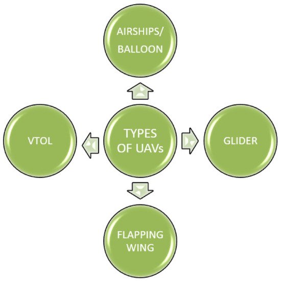
2.4. Different Types of UAVs in Space

It is necessary to justify how UAVs fulfil the primary mission specifications for specified missions to target solar bodies. For instance, it will be a challenge for traditional UAV geometry to travel on other solar bodies. In addition, the size and weight of the UAVs are usually constrained because of the packaging restrictions imposed on the intended solar bodies by the launch vehicle [29]. Therefore, different aerodynamic, performance, regulation, and structural analyses are carried out in the design process to improve the performance of the UAVs. For planetary exploration, there are many configurations, such as balloons, airships, fixed wings, helicopters, rotary wings cyclocopters, gliders, VTOLs, flapping wings, and tilt-rotors. Figure 1 shows the type of UAVs for planetary investigation.
Figure 1. Type of UAVs for planetary investigation.
An airship or balloon is an aircraft carrier that requires no external power to navigate [30]. The balloon is a straightforward technology that requires no power to maintain altitude. Power is only required for instruments and payloads. However, balloons face many difficulties in changing the altitude and location. For example, it cannot stay in the Sun. Balloons also face difficulty in station keeping them, concluding that they are not flexible enough in atmospheric science. However, airships are challenging to place and deploy at a low speed [31]. There are three different kinds of balloons capable of planetary exploration, including super pressure balloons, standard helium balloons, and Montgolfiere balloons.
VTOL is created by incorporating the advantages of both multi-copter and fixed-wing aircraft. Multi-copters can perform vertical take-offs and landings, but their rotary-wing rotor could not pass the sound velocity. On the other side, aircraft can go higher, but heavy lift requires an airstrip. Similar is the case for space exploration. A separate control technique is necessary to transform flight modes between horizontal and vertical configurations in other solar bodies. However, it is possible to imagine hybrids of flying wing and rotary wing UAVs as the future of space UAV setups [32]. The latest studies have focused on the possibility of designing aerial VTOL vehicles that could assist in our solar system’s discovery of different celestial bodies. Specifically, the effectiveness of VTOL vehicles is being researched to support missions to Mars’ surface, Titan, and Venus. The NASA Ames Research Centre studied different rotary-wing aero-mechanics and proof of concept problems underlying the production of vertical lift aerial vehicles for planetary science missions [33]. In addition, the performance of rover and rotor measurements by creating a required condition of atmosphere on Mars’ surface, co-axial helicopter through radio control to promote studying Mars’ surface, VTOL aircraft for studying titan surface [34].
A glider is an aircraft of a unique nature and has no engine. In-flight, in contrast to the four forces operating on a powered aircraft, a glider has three forces. The forces of lift, drag, and weight are revealed to all aircraft types. The powered aircraft has a thrust-producing motor, although there is no thrust in the glider [34]. In the 1960s to 1970s, NASA thought of using another concept for space exploration: the paraglider. Invented in the early 1960s by Francis M. Rogallo, the Rogallo wing used lightweight fabric airfoils arranged in a V-shape. More accurate than a parachute, the lightweight wing could be guided. Plus, instead of a splash landing in the water, the astronauts could operate the wing to glide to a stable landing on the ground. First, Rogallo thought about using the versatile recreational wing. After deciding that there was nowhere to market his proposal for public use, he presented it to the space industry. It may not be used for space landings, but it has become part of a common sport. Kitty Hawk, North Carolina, where the Wright Brothers discovered another famous way to fly, is one of the most popular places in America for hang gliding [12].
Flying a UAV for an interplanetary mission, such as for Mars, Venus, and Titan, is a major challenge, largely because of environmental constraints. The generated lift force of a wing is proportional to the atmospheric density, velocity, and wing area, as shown previously. Perhaps new flying concepts, such as flapping wings, can be well adapted for the low density and highly viscous atmosphere for this purpose [35]. As the power base of the UAV, the ornithopter or ‘flapping wing’ incorporates bird flight dynamics [36]. Due to the severe power requirements for the flapping process, there will be a lack of manoeuvrability and flight time as major drawbacks. However, the ornithopter UAV may become more popular with time as this technology progresses.

3. Simulation

Figure 2 shows the system model for UAV deployment on Mars. The aeroshell separates from the spacecraft after the missile is launched to the targeted planet, and the spacecraft enters the planet’s orbit. The spacecraft performs a quick burn to set up a fly-by trajectory to release the aeroshell on an entry trajectory. The aeroshell should normally reach the atmosphere of the targeted solar at a shallow angle. Due to the shallow entry angle, space UAVs will deploy at sufficient altitudes to meet the flight level. After the deployment is complete, a pull-up operation is performed to determine the controlled flight level. In other words, the UAV should detach from the aeroshell during the deployment process. It should then deploy its tail and wings. UAVs should also recover from a dive while retaining as much altitude as possible.
Figure 2. Methodology for the deployment of UAV on Mars.
In this design model, we build a UAV prototype that is capable of flying on Mars’ surface. The model consists of two major blocks, i.e., flight-control block and model-based block. The flight-control block consists of the actual flight code and code control logic on the prototype UAV model. The flight-control block consists of a controller block, a state estimator block, and other logic blocks.
In the model-based block, model-based design is tuned and tweaks flight code. We can use this model code block to the real prototype UAV hardware model. The model-based design block consists of plant, environment, and sensor blocks. Figure 3 shows the block diagram of the prototype UAV model.
Figure 3. Block diagram of the prototype UAV model.
For the inside design of the various blocks and sub-blocks, it is necessary to have explicit knowledge about the aim of the UAV prototype. The environment in which the UAV is expected to have a flight and the surface conditions above which the flight is assumed to occur are some of the major concerns while designing the blocks.
Table 4 shows the different environmental parameters set in the environment block to design the UAV prototype for the surface of Mars. The environmental parameters of Mars’ surface are taken from the values reported by Mariner 9 [37].
Table 4. Parameters considered for Mars flight.
Parameters Mars [38] (Reported)
Volume (km3) 16.318
Mass (1024 kg) 0.64171
Gravity (m/s2) 3.711
Air pressure (bars) 6.1 × 10⁴
Air density 0.020
Speed of sound (m/s) 240
Atmospheric temperature (Kelvin) 273 + 15

3.1. Environmental Conditions

3.1.1. Air Pressure

The air pressure value at the surface of Mars is approximately 610 Pascal [27]. This means the air pressure on Mars is less than 1% of that on Earth. As a result, the air on Mars is significantly leaner than it is on Earth. As a result, the critical source of concern when developing a prototype UAV is whether there would be enough lift. The UAV is possibly heavier than air. For a UAV to fly successfully in a planets’ atmosphere, four forces are obligatory: lift, drag, weight, and thrust. Figure 4 shows the aerodynamics of the UAV. A coordinated system is used in the UAV flight. The coordinate system allows keeping track of an aircraft or Spacecraft’s position and orientation in space. Here, three coordinate systems are used in the UAV’s flight mechanism. These coordinate systems are:
Figure 4. Aerodynamics of the UAV.
Inertial System: Inertial system is attached to the planetary surface, does not move.
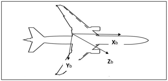
Fixed Body Frame: This frame is attached to the airframe and moves with the UAV.
Aerodynamic frame: The average velocity of the aircraft’s centre of mass defines this frame. The UAV is also equipped with a dynamic frame.
The three axes on the UAV prototype are Xb, Yb, and Zb. These represent the forward, right, and positive downward axis, respectively. The engine of a flying vehicle generally provides thrust. Thrust must surpass the vehicles’ drag for a successful flight. The wings provide the lift of the vehicle. UAV’s lift should equal its weight for the flight to flourish. The UAV’s smooth shape will probably reduce drag, and the materials it is made up of will affect its weight.

3.1.2. Gravity

It is evident that for designing a prototype UAV, decreased weight and an increased lift are the two major goals to be achieved. Based on Newton’s theory of universal gravitation, when talking about a spherical body, such as a planet, the gravitational force is directly proportional to the planet’s mass and inversely proportional to the square of the radius of the planetary body. Equations (1) and (2) are based on Newton’s theory of universal gravitation and shows the formula for the gravitational force of Mars [39]. Table 3 shows the notation and parametric values of Equation (1) [40].

g = Gm/r2

g = 3.711 m/s2

where:
  • g is the gravity of the Mars
  • G is the gravitational constant
  • m is the mass of the planet Mars
  • r is the radius of the Mars.
Table 3. Notation and parametric values.
Parameters Values
Gravitational Constant 6.674 × 10⁻¹¹m3 kg−1 s−2
Mass of Mars 6.42 × 10²³ kg
Radius of Mars 3.38 × 10⁶

3.1.3. Air Density

Air density directly impacts UAVs aerodynamically and in terms of engine performance. Air density affects nearly every aspect of a UAV’s flight. In less dense air, standard measurements, such as take-off distances, rate of climb, landing distance, would all be increased, thus reducing the performance. Atmospheric density, in general, is defined as the mass per unit volume of a planet’s atmosphere.

3.1.4. Air Temperature

Air temperature plays a vital part in the behaviour of the flight of UAVs. The lift generated by a UAV depends mainly on the air density. Air density depends on the air temperature and altitude. At higher temperatures, air density is reduced. As a result, a UAV will have to travel faster to generate enough lift for take-off. The air temperature at Mars is 210 K (approximately).

3.1.5. Speed of Sound

Speed of sound is defined as the distance travelled via sound waves in a unit of time. This parameter plays a significant role in designing the UAV prototype. Some of the major uses are:
Useful in separating the flight regimes into two distinct areas with distinct flow conduct.
Assists in converting compressible flow geometry to one that can be measured using simpler, incompressible methods.
Efficient air travel and the maximum practical flight speed will be restricted.
Provides a hint to the designer about how to drive this boundary higher. For example, the speed of sound at Mars’ surface is 240 m/s2, and [37] this is comparatively lower than the Earth’s (343 m/s2).
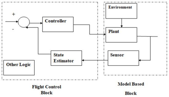
3.2. Sensors Block

3.2.1. Inertial Measurement Unit (IMU)

The IMU is used to monitor angular rates and translation accelerations. IMUs can track speed, position, accelerated specific force, and angular rate, among other things. An IMU’s tools have been used to collect various data types. The tools are:
Accelerometer: To capture speed and acceleration.
Gyroscope: A gyroscope is a device that measures spin and spindle speed.
Magnetometer: Cardinal direction is determined via a magnetometer.

3.2.2. Camera

A camera is for estimating optical flow. Optical flow is an image processing technique. The camera will take images at 60 frames per second (FPS) through the optical flow technique. This method will aid the sensor in determining how objects move from one picture to another. The UAV can calculate apparent horizontal motion or velocity using the camera sensor. An immersive stereoscopic teleoperation system navigation for UAV improves autonomous navigation and provides better capabilities for collecting video footage for training future autonomous and semiautonomous control policies is used here.

3.2.3. Ultrasound Sensor

An ultrasound sensor is used to determine altitude. First, the lateral distances are measured using an ultrasonic sensor. Then, it sends a high sound pulse and counts how long it takes for the sound to rebound off the ground and back to the sensor. The altitude between both the floor and the UAV can be calculated using these measurements. Unfortunately, after about 30 feet of altitude, the reflected sound is far too low for the sensor to detect.

3.2.4. Pressure Sensor

The pressure sensor is used to sense pressure, which will further work in calculating altitude. As the UAV flies higher in altitude, the pressure of the air falls slightly. The pressure sensor uses this trivial change in pressure to guesstimate how the elevation of the UAV changes.

4. Opportunities, Challenges, and Future Scope

UAVs are considered to be a powerful tool for the exploration of planets. A portal for extremely high advancement in planetary exploration will be opened by using UAVs to explore a spatial body. Furthermore, UAVs can correct entry errors into the atmosphere and provide a fundamental scientific understanding of the planet’s atmosphere, surface, and interior. Therefore, there will be many opportunities to use UAVs for space exploration:
Ample economic power: Today’s space explorations are limited by the individual missions’ mass and life span considerations. Over time, the current power system is exhausted in the spacecraft, so the amount of usable power is reduced as the mission progresses. UAVs will open up the gateway of exploring a spatial body with plenty of economic power.
Scientific investigation: For the scientific investigation of the planet’s geology or even scouting missions for possible human outposts, a UAV might open up the opportunity by covering large regions of Mars.
Systematic mapping: UAVs fly independently or via remote control/piloting. Autonomous flights are pre-programmed with computers each time and are suitable for the systematic mapping of landscapes.
Affordable Space Access: Loading a single pound of mass into low Earth orbit costs around 10,000 USD today. The construction and manufacture of the launch system is a crucial part of this expense. Nearly 40% of the overall cost is attributed to processing from the ground and launch. The use of UAVs for interplanetary missions will allow access to space economically.
While these UAVs are useful for space exploration, there are still risks associated with the implementation, flying requirements, and data retrieval associated with the proposed concept. For those in the future working nearest to the research, costs, efficiency, and safety tend to be at the top of the agenda, yet these represent just a portion of sustainability concerns. Some factors, such as the UAVs’ trajectory planning, path planning, long-term endurance, best suited aerodynamic design, and compatible propulsion systems, should remain the top concern. It should be observed that the design and development of space UAVs should be accomplished depending on the environment. For one, because of the amount of gravity on Mars’ surface, the weights of the UAV should be monitored. The UAV’s endurance is largely restricted by the energy available. Mars’ surface went undercover a few years ago; Mars’ dust storms are common, but for unexplained causes, a gigantic one becomes global, covering the face of the planet every decade or so. However, Mars’ dust storms are not entirely harmless; storms can pose a deadly exploration threat. On Mars, individual dust particles are very tiny and mildly electrostatic, but they adhere like styrofoam packaging peanuts to the surfaces they touch [40]. The one that destroyed NASA’s Opportunity rover in 2018 by coating its solar panels in the dust is one big example. Different propulsion systems and fuel/oxidisers that supply the UAV with energy and the additional techniques that provide the UAV with ample power for a longer duration should be considered in the future. Future researchers are expected to improve the flight path based on motion, kinematics, and energies for flight endurance.

References

  1. Launius, R.D. Frontiers of Space Exploration; Greenwood Publishing Group: Westport, CT, USA, 2004.
  2. Hassanalian, M.; Abdelkefi, A. Classifications, applications, and design challenges of drones: A review. Prog. Aerosp. Sci. 2017, 91, 99–131.
  3. Sharma, V.; Song, F.; You, I.; Chao, H.-C. Efficient Management and Fast Handovers in Software Defined Wireless Networks Using UAVs. IEEE Netw. 2017, 31, 78–85.
  4. Kotecha, K.; Garg, D.; Mishra, B.; Narang, P.; Mishra, V.K. Background Invariant Faster Motion Modeling for Drone Action Recognition. Drones 2021, 5, 87.
  5. Almalki, F.A.; Soufiene, B.O.; Alsamhi, S.H.; Sakli, H. A low-cost platform for environmental smart farming monitoring system based on IoT and UAVs. Sustainability 2021, 13, 5908.
  6. Gupta, A.; Sundhan, S.; Gupta, S.K.; Alsamhi, S.H.; Rashid, M. Collaboration of UAV and HetNet for better QoS: A comparative study. Int. J. Veh. Inf. Commun. Syst. 2020, 53, 309–333.
  7. Catling, D.C.; Leovy, C. Mars Atmosphere: History and Surface Interactions. In Encyclopedia of the Solar System; Elsevier: Amsterdam, The Netherlands, 2007; pp. 301–314.
  8. Guynn, M.; Croom, M.; Smith, S.; Parks, R.; Gelhausen, P. Evolution of a Mars Airplane Concept for the ARES Mars Scout Mission. In Proceedings of the 2nd AIAA “Unmanned Unlimited” Conference and Workshop & Exhibit, San Diego, CA, USA, 15–18 September 2003; p. 6578.
  9. Williams, M. Available online: https://www.universetoday.com/35796/atmosphere-of-the-planets/ (accessed on 1 December 2020).
  10. The European Space Agency. Available online: https://www.esa.int/ESA_Multimedia/Images/2018/04/Comparing_the_atmospheres_of_Mars_and_Earth#:~:text=Mars%20is%20about%20half%20the,rich%20in%20nitrogen%20and%20oxygen (accessed on 1 December 2020).
  11. Titus, T.N.; Colaprete, A. Mars Atmospheric Surface Interactions and the CO2 Cycle. 2005. Available online: https://ui.adsabs.harvard.edu/abs/2005EOSTr..86..462T/abstract (accessed on 5 December 2020).
  12. Reed, R.D. High-Flying Mini-Sniffer RPV-Mars Bound; NASA Flight Research Center Edwards: Edwards, AL, USA, 1978.
  13. Pipenberg, B.T.; Keennon, M.; Tyler, J.; Hibbs, B.; Langberg, S.; Balaram, J.; Grip, H.F.; Pempejian, J. Design and Fabrication of the Mars Helicopter Rotor, Airframe, and Landing Gear Systems. In Proceedings of the AIAA Scitech 2019 Forum, San Diego, CA, USA, 7–11 January 2019; p. 0620.
  14. Patel, A. Design, Modelling, and Control of a Space UAV for Mars Exploration; Lulea University of Technology: Lulea, Sweden, 2021.
  15. Johansson, M. Experimental and Computational Evaluation of Capabilities of Predicting Aerodynamic Performance for a Mars Helicopter Rotor; Chalmers University of Technology: Gothenburg, Sweden, 2017.
  16. Mishra, I.; Kumar, A.; Malhotra, V. Conceptual Design of an Unmanned Aerial Vehicle for Mars Exploration. Eur. J. Eng. Technol. Res. 2021, 6, 111–117.
  17. DeSouza, C. Conceptual design of an unmanned aerial vehicle for mars exploration (MISCAV). In Proceedings of the 44th Lunar and Planetary Science Conference, Bruxelles, Belgium, 5 August 2013; pp. 1–2.
  18. Smith, S.; Hahn, A.; Johnson, W.; Kinney, D.; Pollitt, J.; Reuther, J. The design of the Canyon Flyer, an airplane for Mars exploration. In Proceedings of the 38th Aerospace Sciences Meeting and Exhibit, Reno, NV, USA, 10–13 January 2000; p. 514.
  19. Sharma, V.; Srin ivasan, K.; Chao, H.C.; Hua, K.L.; Cheng, W.H. Intelligent deployment of UAVs in 5G heterogeneous communication environment for improved coverage. J. Netw. Comput. Appl. 2017, 85, 94–105.
  20. Rumford, T.E. Demonstration of autonomous rendezvous technology (DART) project summary. In Space Systems Technology and Operations; SPIE: Washington, DC, USA, 2003; Volume 5088, pp. 10–19.
  21. Available online: https://www.popsci.com/military-aviation-amp-space/article/2009-03/gallery-top-10-nasa-probe-failures/ (accessed on 21 February 2021).
  22. Blackburn, M.; Busser, R.; Nauman, A.; Knickerbocker, R.; Kasuda, R. Mars Polar Lander fault identification using model-based testing. In Proceedings of the 26th Annual NASA Goddard Software Engineering Workshop, Greenbelt, MD, USA, 5–6 December 2002; pp. 128–135.
  23. Available online: https://en.wikipedia.org/wiki/NOAA-19 (accessed on 21 February 2021).
  24. Available online: https://mars.nasa.gov/news/1854/the-fact-and-fiction-of-Martian-dust-storms/ (accessed on 24 February 2021).
  25. Withers, P.; Weiner, S.; Ferreri, N.R. Recovery and validation of Mars ionospheric electron density profiles from Mariner 9. Earth Planets Space 2015, 67, 23403.
  26. Available online: https://phys.org/news/2016-12-strong-gravity-mars.html#:~:text=On%20top%20that%2C%20the%20gravity,only%2038%20kg%20on%20Mars (accessed on 7 April 2021).
  27. Available online: https://byjus.com/physics/value-of-g/ (accessed on 7 April 2021).
  28. Withers, P.; Felici, M.; Mendillo, M.; Moore, L.; Narvaez, C.; Vogt, M.F.; Jakosky, B.M. First ionospheric results from the MAVEN radio occultation science experiment (ROSE). Journal of Geophysical Research: Space Physics 2018, 123, 4171–4180.
  29. Available online: https://en.wikipedia.org/wiki/Aerobot/ (accessed on 22 January 2021).
  30. Available online: http://www.gaerospace.com/tag/space-balloons/ (accessed on 22 January 2021).
  31. Salazar, R.D.; Hassanalian, M.; Abdelkefi, A. Defining a conceptual design for a tilt-rotor micro air vehicle for a well-defined mission. In Proceedings of the 55th AIAA Aerospace Sciences Meeting, Grapevine, TX, USA, 9–13 January 2017; p. 0239.
  32. Michelson, R.C.; Naqvi, M.A. Beyond Biologically Inspired Insect Flight. von Karman Institute for Fluid Dynamics RTO/AVT Lecture Series on Low Reynolds Number Aerodynamics on Aircraft Including Applications in Emergening UAV Technology; von Karman Institute for Fluid Dynamics: Sint-Genesius-Rode, Belgium, 2003; pp. 1–19.
  33. Available online: https://www.911security.com/learn/airspace-security/drone-fundamentals/types-of-drones-flapping-wing (accessed on 25 January 2021).
  34. Hassanalian, M.; Abdelkefi, A.; Wei, M.; Ziaei-Rad, S. A novel methodology for wing sizing of bio-inspired flapping wing micro air vehicles: Theory and prototype. Acta Mech. 2016, 228, 1097–1113.
  35. Oyama, A.; Fujii, K. A Study on Airfoil Design for Future Mars Airplane. In Proceedings of the 44th AIAA Aerospace Sciences Meeting and Exhibit, Reno, NV, USA, 9–12 January 2006.
  36. Barnes, J.W.; Lemke, L.; Foch, R.; McKay, C.P.; Beyer, R.A.; Radebaugh, J.; Atkinson, D.H.; Lorenz, R.; Le Mouélic, S.; Rodriguez, S.; et al. AVIATR—Aerial Vehicle for In-situ and Airborne Titan Reconnaissance. Exp. Astron. 2011, 33, 55–127.
  37. Available online: https://en.wikipedia.org/wiki/Atmosphere_of_Mars#:~:text=It%20also%20contains%20trace%20levels,1%25%20of%20the%20Earth’s%20value (accessed on 7 April 2021).
  38. Alsamhi, S.H.; Ma, O.; Ansari, M.S. Convergence of Machine Learning and Robotics Communication in Collaborative Assembly: Mobility, Connectivity and Future Perspectives. J. Intell. Robot. Syst. 2019, 98, 541–566.
  39. Available online: https://mars.nasa.gov/mars2020/participate/sounds/#:~:text=With%20an%20average%20surface%20temperature,meters%20per%20second)%20on%20Earth (accessed on 8 April 2021).
  40. Available online: https://www.sciencemag.org/news/2020/11/Martian-dust-storms-parch-planet-driving-water-space#:~:text (accessed on 24 February 2021).
More
Information
Subjects: Remote Sensing
Contributor MDPI registered users' name will be linked to their SciProfiles pages. To register with us, please refer to https://encyclopedia.pub/register :
View Times: 715
Revisions: 2 times (View History)
Update Date: 24 Jan 2022
1000/1000
Video Production Service