Your browser does not fully support modern features. Please upgrade for a smoother experience.
Submitted Successfully!
 +1 credit
Thank you for your contribution! You can also upload a video entry or images related to this topic.
For video creation, please contact our Academic Video Service.
| Version | Summary | Created by | Modification | Content Size | Created at | Operation |
|---|---|---|---|---|---|---|
| 1 | Soheil jafari | + 7305 word(s) | 7305 | 2022-01-13 03:39:48 | | | |
| 2 | Camila Xu | Meta information modification | 7305 | 2022-01-14 02:25:04 | | |
Video Upload Options
We provide professional Academic Video Service to translate complex research into visually appealing presentations. Would you like to try it?
Cite
If you have any further questions, please contact Encyclopedia Editorial Office.
Jafari, S. Thermal Management System. Encyclopedia. Available online: https://encyclopedia.pub/entry/18224 (accessed on 24 June 2026).
Jafari S. Thermal Management System. Encyclopedia. Available at: https://encyclopedia.pub/entry/18224. Accessed June 24, 2026.
Jafari, Soheil. "Thermal Management System" Encyclopedia, https://encyclopedia.pub/entry/18224 (accessed June 24, 2026).
Jafari, S. (2022, January 13). Thermal Management System. In Encyclopedia. https://encyclopedia.pub/entry/18224
Jafari, Soheil. "Thermal Management System." Encyclopedia. Web. 13 January, 2022.
Copy Citation
In gas turbine engines, Thermal Management (TM) is a concept of utilising the engine fluid systems to extract the excess heat generated within the various components and systems of the engine as well as employing the extracted heat for multiple functions that would improve the engine’s performance.
thermal management system
hydrogen-powered propulsion
fuel cells
1. Thermal Management
Thermal Management is a concept of utilising the engine fluid systems to extract the excess heat generated within the various components and systems of the engine and employing the extracted heat for multiple functions that would improve the engine’s performance. Thus, developing any TMS for an aero-engine requires integrating all the three Fluid Systems in the engine, i.e., the Air, Oil, and Fuel Systems [1][2].
As the aero-engine technology transitions towards higher Overall Pressure Ratios (OPRs) and higher By-pass Ratios (BPRs) to achieve the demands of higher thrust, power, and improved Specific Fuel Consumptions (SFC) [3], some of the key challenges from the TMS perspective are,
-
The higher component temperatures.
-
The higher temperature of the working fluids.
-
Higher heat generated within the Engine and its sub-systems owing to points 1 and 2.
Therefore, the TMS and its significance in effectively utilising the excess heat to improve the engine performance becomes a critical issue. In the state-of-the-art aero-engine technologies, the recognised heat sources for which the TMS design caters decisively are accessory gearbox (AGB), bearings, pumps, and generators. Furthermore, the power gearbox and the constant speed drives in the geared turbofan engines are also heat sources that require the effective TMS to enhance its performance and operability [2].
To simplify, the main objectives of the TMS are to [1],
-
Maximise the utilisation of heat generated and avoid unnecessary heat losses.
-
Enable various components and systems to operate at an acceptable limit to ensure higher component life and performance and thereby reduce the intervention for maintenance and services and so forth.
From the Thermal Management perspective, it is worthwhile to note the primary functions of the said Fluid Systems in the engine, and they are classified broadly as [1],
-
Fuel System—Designed to act as a heat sink for the Oil System that scavenges heat from various components/systems in the engine.
-
Oil System—Designed to scavenge the excess heat while providing essential cooling and corrosion protection to specific components/systems in the engine.
-
(Internal or Secondary) Air System—Aids in cooling the engine components, anti-icing, and cabin environment control.
Although the cooling flow of air is deemed a heat load management practice for the engine components, this does not fall within the scope of this paper. However, the reader(s) can note that a comprehensive review of the cooling mechanisms, physics-based modelling and associated studies, along with the involved control system mechanisms, are available in the literature [2]. Yet another aspect of the air system that is associated with the thermal management is an integration with the oil system where the heat exchangers like the surface air-cooled oil Coolers (SACOC) are employed to further maintain the required operating temperature of the oil, following a heat exchange between the oil and fuel system via the fuel oil heat exchanger (FOHE).
Thus, a visualisation of the thermal management model, which is typical and simplified, is as shown in Figure 1.
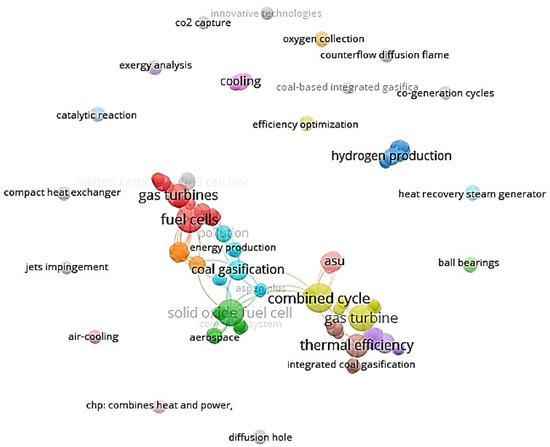
Figure 1. Network structure of keywords in Phase 1 generated using VOSViewer Clustering.
The origin of this model is through a patent registered in 1987 by United Technologies Corporation based on an integration of the fuel, oil, and air systems to meet the cooling requirements of gas turbine engines [2]. For the benefit of the reader(s), it is worth noting that important information is available in the literature, such as the historical development in the area of TMS for gas turbines, various configurations for consideration. In addition, the utilisation of different working fluids such as water, therminol, and thermally neutral heat transfer fluid (TNHTF) are addressed [2].
The TMS model shown in Figure 2 is acceptable as a preliminary concept for an aero-engine that utilises Hydrogen as the fuel. Hydrogen is in its gaseous state at room temperature due to its low boiling point (−20.1 K at 1 atm pressure), while its auto-ignition temperature is much higher at 773 K in comparison to its counterpart convention fossil fuels [4][5]. Thus, from a thermal management perspective and to further optimise the engine’s performance, the wide temperature range for operation is offered by hydrogen as it can act as a heat sink.
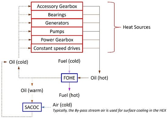
Figure 2. Simplified schematic of a typical TMS model for an aero-engine.
A typical fuel-cooled thermal management model, i.e., the fuel system architecture employed in the current technologies, can be visualised in Figure 3. Thus, it enables the heat dissipation from various engine sources to the fuel raising its temperature to the desired value before introducing it into the combustor.
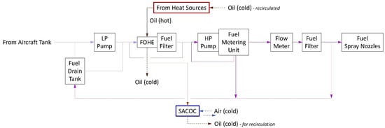
Figure 3. Typical fuel-cooled TMS model or typical fuel system architecture in an aero-engine [1].
The fuel system architecture shown in Figure 3 is typical of the state-of-the-art engine technologies available in the market. For the application of hydrogen as fuel in the engine, the current model requires further modifications. The modifications necessary for the engine fuel system for thermal management and the fuel system’s operation with hydrogen covers the subsequent section.
2. Engine Fuel System Architecture for Utilisation of Hydrogen
As observed in Figure 3, the fuel system comprises vital components such as fuel drain tank, low pressure (LP) and high pressure (HP) pumps, heat exchanger (Fuel-Oil), fuel filters, fuel metering unit and flow meter and supply pipes delivering fuel to the fuel spray nozzles (FSNs). In addition to these, various other components, such as the control valve, pressure regulating valves, and flow regulators, are necessary for the safe and reliable functioning of the system. For utilisation of Hydrogen, another essential feature to be considered during the conceptualisation and design of the fuel system is Insulation. In the subsequent sections, the key components of the fuel system, such as the tanks, heat exchangers, pumps, and insulations, are discussed in more detail. The fuel filters, fuel metering unit, and flow meter are not considered within the scope of this paper as their operation is not in tandem with the thermal management system of the engine.
2.1. Tanks and Fuel Drain Tank
Hydrogen may be in its gaseous state or liquid state during storage, but in either case, the main challenge arises from its volumetric density and thus, for aviation, utilising Liquid Hydrogen (LH2) is deemed more favourable. Another significant challenge is maintaining hydrogen in the liquid state at around 20–30 K throughout the whole mission of the aircraft. The thermal heat leakage tends to raise the fuel temperature in the tanks. Though the withdrawal of the fuel from the tanks would reduce this temperature change, there would be vaporisation of the remaining fuel due to the temperature change, which occupies the void created by the fuel flowing out from the tank [6].
The literature distinguishes two types of tank design—integral tanks that fit closely with the airframe design and non-integral [7]. The former needs a more precise stress design than the latter, and in terms of volume’s utilisation is believed to be better, allowing better aerodynamic performances while reducing the fuselage size. Moreover, maintenance of these integral tanks is easier thanks to being more readily accessible for inspection and repairs of the insulation [8]. Integral tank structures have also been selected in [9][10][11], contrary to [12], which asserted in 2012 that the TRL of integral tank technology was still too low. Although non-integral tanks may allow more straightforward design and simulation processes to understand the system behaviour, the former is seemingly preferred.
It is also worth noting that in ENABLEH2 research (an EU funded consortium led by Cranfield University), a variety of aircraft configurations have been assessed against numerous criteria and concluded that the blended-wing configuration and the tube-wing configuration with tanks above the passenger cabin (as proposed by Cryoplane) are appropriate for long-range missions [6].
Based on the discussions with the researchers involved with hydrogen propulsion technology at Cranfield University, it could be estimated that the engine fuel system is required to deliver the fuel to the FSNs or combustor at a temperature around 400~500 K for better thermal performance of the engine. Furthermore, at the inlet of the engine fuel system, the fuel may be delivered by the aircraft boost pumps at around 25~26 K at about 14~20 bar pressure. These values are indicative in nature, and the purpose of mentioning these values is only to understand the potential range at which the engine fuel system need to operate from the point of entry of the fuel from aircraft to the FSNs or combustor.
From the engine fuel system perspective, some of the state-of-the-art engines employ a fuel drain tank with the primary purpose of collecting the residual fuel from the FSNs and the fuel manifold after a normal shutdown of the engine on the ground to prevent fuel lacquering and any carbon deposits in the FSNs and tubes. This fuel is usually drained back to the tank via a dump valve to recirculate into the engine fuel system upon engine restart. In the event of an in-flight shutdown, the dump valve remains closed, leaving the fuel available in the manifolds and the FSNs to aid with the in-flight restart of the engine. Generally, the sizing of the drain tank would be to collect enough fuel, which would satisfy the requirements for one normal shutdown and three failed starts.
During the shutdown on the ground or during the excess fuel spill back to the tank in running condition, the fuel is at a higher temperature and in a vapour state, far above the critical temperature and pressure. Hence, the design of the fuel drain tank becomes more complicated as various issues such as size, weight, venting, and much more turn out to be necessary for safety and reliability, as venting into a hotter environment of the engine could potentially cause deflagration or detonation [6]. Therefore, it would be more conducive to circulate the excess fuel during running conditions and usual shutdown back to the aircraft tank, which has a much larger volume, operating at lower temperature and pressure than the flow spilt back. Such spill-back to aircraft tank methodology has been in practice in many current engine technologies; however, it is worthwhile to mention that it may be necessary to employ some cooling practices and pressure reducing techniques along the supply lines that is spilling the flow back to the aircraft tank for safety and reliability purposes. In the parametric study of tank integration for hydrogen [6], the conclusion was that the tank weight behaves mainly as a function of its diameter, and the choice of insulation solely depends on the diameter and the venting strategy. Additionally, it concluded that the dormancy time (minimum time required for the tank pressure to be equal to venting pressure) is also an essential parameter for design consideration. With the fuel in its vapour state and at high temperature and pressure spilling into the fuel drain tank, the need for the venting strategy in the engine becomes significant as the dormancy time is affected.
Another prime reason for this choice, i.e., spill-back to aircraft tank, is the size and weight of the tank. The low density of hydrogen implies that the volume in terms of space for the tank required is much more prominent than its counterparts in current technologies. Thus, it has implications on the mechanical design of structures and accessories required for the installation of the drain tank, the life expectancy of components, the ease of accessibility for maintenance of these and other vital components in the vicinity of the tank and much more.
Figure 4 shows the architecture of the engine fuel system with spill-back to the aircraft tank. In addition, to cool the excess spill back to the aircraft tank, a surface air-cooled fuel cooler (SACFC) is proposed as a heat exchanger unit in this architecture. The assumption revolves around the working principle of this heat exchanger, which is to be the same as that of the SACOC that uses the cold bypass stream air intending to provide convective cooling to the hot fuel before it reaches the aircraft tank and ensures that the fuel temperature reduces to an optimum temperature. This architecture stands as the base for further discussions in the subsequent sections of the paper that cover the different engine fuel system configurations based on the heat management strategies.
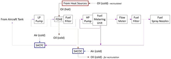
Figure 4. Proposed fuel-cooled TMS configuration with spill-back to aircraft tank.
2.2. Heat Exchangers (HEX)
As discussed in the previous section, using hydrogen as a fuel opens the door to optimise the engine performance, improving the life expectancy of various components while controlling the temperature of the fuel [11][13]. Heat exchanger units play a significant role to achieve this goal. There are many different types of heat exchangers, but the typical ones are shell-and-tube, crossflow and double-pipe heat exchangers, and these units can be employed as compressor precoolers and compressor intercoolers as they are promising in terms of performance; however, it would involve a considerable complexity from application perspective within the engine architecture. They can also be used to cool down the compressor bleed air used for turbine cooling to increase the turbine life expectancy. Furthermore, installing a heat exchanger in the nozzle allows increasing the temperature of Hydrogen using the thermal energy expelled by the engine. Such options were proposed and assessed by NASA in 1978 [11] and validated in the literature [13]. Hence, these works of literature serve as solid ground to start exploring various applications of the heat exchangers in the engine and thereby the possible engine fuel system configurations.
For this purpose, the tool TURBOMATCH, developed at Cranfield University, was used due to its flexibility to adapt and customise any aero-engine to the user’s needs. One of the limitations of the TURBOMATCH is that it cannot calculate the outlet parameters of the heat exchangers. Hence, to offer more flexibility for the users, the TURBOMATCH needs to be accompanied by an external tool that can contemplate different heat exchangers. A direct consequence of this is the loss of some fidelity to widen its capabilities as the rest of the literature concerning heat exchangers do, i.e., to say, a slightly reduced accuracy to allow a considerable increase in its adaptability [14].
The structure of this external tool developed using MATLAB follows a method commonly known as ε-NTU, where ε refers to effectiveness and NTU to Number of Transfer Units. An explanation of this method goes beyond the scope of this paper, but it is worth highlighting that this structure reduces the necessary iterations and input parameters to the minimum, especially in comparison with another commonly used technique—the LMTD method. Thus, allowing the users to execute it without knowing neither any outlet parameters of the heat exchanger nor heat exchanger’s geometry while ensuring that the speed of the calculations is not in jeopardy. As this is the case, two different paths follow for execution [14],
-
The first path solves the thermal problem, in which some geometrical parameters can be used as input to obtain the desired thermal outlet conditions.
-
The second path solves the sizing problem, in which imposing some thermal conditions allows the tool to offer suitable geometrical ranges for those conditions (more precisely, the U-A parameter, where U stands for overall heat exchange coefficient and A is the heat exchange surface).
For a broad perspective of the thermal problem in three different types of heat exchangers, i.e., double-pipe HEX (counter-flow condition), cross-flow HEX (unmixed condition) and shell-and tube HEX (for single-pass, N = 1) effectiveness in terms of the number of transfer units are calculated. The calculated results are plotted and shown in Figure 5. Via the sizing problem, generating a similar plot is possible, but it includes the U-A parameters for the heat exchangers.
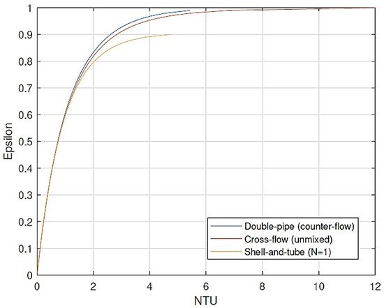
Figure 5. NTU vs. ε comparison for different types of heat exchangers.
Solving either of the problems using the tool and calculating the pressure drop within the heat exchanger, the necessary inputs for simulations in TURBOMATCH would be available [14]. Furthermore, these tools simulate the Rolls-Royce Avon engine for different cases. The first simulation used kerosene as the fuel and without any heat exchangers. In the second simulation, liquid hydrogen (LH2) was used as the fuel without any heat exchangers.
Further, two more simulations with LH2 including, a heat exchanger in different positions in each case, is carried out. The simulations aid in understanding the impact of the fuel and that of the heat exchangers. The variation of air mass-flow rate with combustor outlet temperatures is as shown in Figure 6 for different engine configurations.
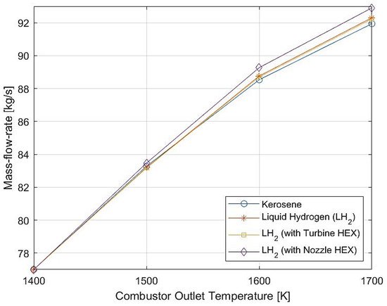
Figure 6. Air mass-flow rate vs. combustor outlet temperature for different configurations.
Similarly, the behaviour of the fuel flow for the configurations mentioned above, with the combustor outlet temperatures, is simulated and shown in Figure 7, indicating that any configuration that uses LH2 results in less fuel consumption as LH2 has a higher gravitometric energy density [15].
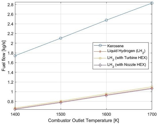
Figure 7. Fuel flow vs. combustor outlet temperature for different configurations.
Furthermore, the simulations also indicate that any configuration of the engine that includes heat exchangers improves the engine’s performance. Specifically, the configuration that includes turbine cooling air heat exchanger provides the most benefit in terms of thrust, as indicated by the results (Figure 8).
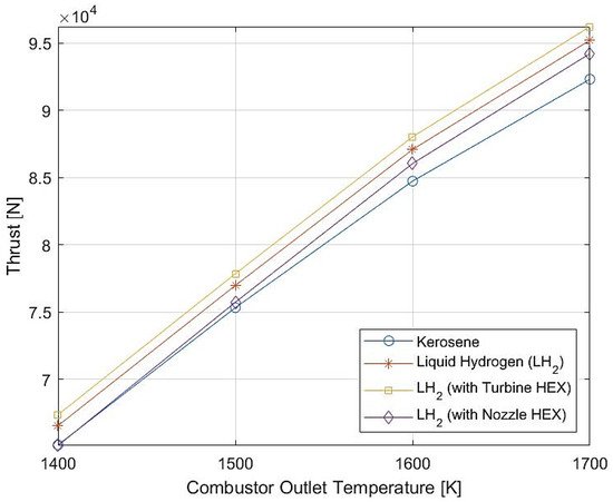
Figure 8. Thrust vs. combustor outlet temperature for different configurations.
These simulations from the tools offer support to the ideas proposed by NASA in the late 1970s [11] and highlight the use of heat exchangers as units that can enhance the engine’s performance. Depending on the number and positioning of the heat exchangers, various configurations of the engine fuel system can be derived. The proposed fuel-cooled TMS model, the different configurations for the engine fuel system are proposed and shown in Figure 9.
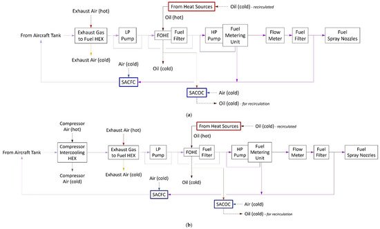
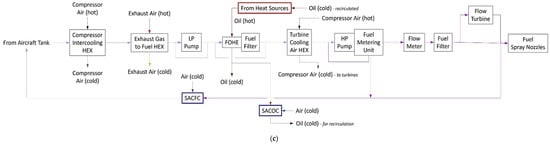
Figure 9. Different configurations of the TMS and engine fuel system architecture; (a) Configuration 1—with Exhaust Gas HEX. (b) Configuration 2—with Compressor intercooling and exhaust gas HEX; (c) Configuration 3—with compressor intercooling HEX, exhaust gas HEX, turbine air cooling HEX and flow turbine. (a) TMS and engine fuel system architecture—Configuration 1. (b) TMS and engine fuel system architecture—Configuration 2. (c) TMS and engine fuel system architecture—Configuration 3.
Configuration 1, shown in Figure 9a, adopts the exhaust gas heat exchanger to utilise the exhaust heat for raising the fuel temperature. The placement of this heat exchanger is upstream of the LP Pump so that the fuel temperature can be raised to some extent before it is pumped further into the fuel circuit. During the filling up of the aircraft tank, if there is any fraction of air left in the tank, the nitrogen (melting point: 63.2 K) [16] and oxygen (melting point: 54.36 K) [17] in the air might form into ice crystals as the operating temperature of the tank for hydrogen is much lower (at around 20~30 K). The heat from the exhaust could potentially raise the fuel temperature so that these ice crystals can melt before they can venture further into the fuel circuit. In addition to this, another benefit of using the exhaust gas HEX is that it can reduce the exhaust gas temperature and thereby the exhaust noise. Since the kinetic energy of the exhaust gas is dependent on the exhaust gas temperature and pressure, rejecting the exhaust heat into the fuel may potentially reduce some energy in the flow and thus reduce the noise emission due to the exhaust gases. Of course, this influences the thrust produced by the engine, as indicated in Figure 8, but this enables the engine to operate at a relatively higher operating setting. The exhaust Ggas HEX design principle can follow the same concept of the SACOC, where the convective heat transfer occurs between the two fluids. Such a model potentially avoids tapping the exhaust air, which may compromise the exhaust mass flow and thrust requirements.
Configuration 2, shown in Figure 9b, includes a compressor intercooling HEX in addition to the exhaust gas HEX. The implementation of an intercooler between the compressor stages increases the useful work of the turbine (as the turbine work remains the same) while the overall compressor work reduces. Since it is much easier to compressor cold air than hot air, it enables the engines to achieve higher OPRs [18]. To avoid bulky and heavy heat exchanging units, the Chalmers University of Technology, Sweden, are investigating this avenue and have proposed a vane-integrated heat exchanger [19] for turbofan applications. This compact heat exchanger is integrated into the compressor vanes and utilises the available aerodynamic surfaces to reject the core heat to the fuel. It also proposes that introducing additional profiled plates can further increase the surface area available for heat dissipation. Though this could lead to increased pressure losses in the engine core, the argument is that the design of such plates with improved radial turning capability would reduce engine size (in terms of length) and weight. Such a configuration would feature an S-duct between two compressors in the engine. A preliminary study of this concept is available in the literature [19]. With such a novel concept for heat exchange, the feasibility and potential of compressor intercooling HEX are deemed desirable for advanced TMS models that are necessary for the utilisation of Hydrogen as a fuel. It is also worth noting that the exhaust gas HEX could also be based on such a concept and can utilise the aerodynamic surfaces of the vanes/struts in the tail bearing housing for HEX integration.
Figure 9c, showing Configuration 3, introduces the turbine cooling air HEX and a flow turbine/expander in addition to the features discussed in Configuration 2. As observed in Figure 8, implementing a turbine cooling air HEX is beneficial in terms of thrust for a given combustor outlet temperature and is proposed for the additional benefit of improving the life expectancy of the turbine components. The hot air from the compressor used for turbine cooling can be passed through a heat exchanger to cool and reject heat to the fuel. Thus, enabling much cooler air introduction for cooling the turbine components. As the engine fuel circuit is much larger and more complex, the pumps required to deliver the fuel must provide higher discharge pressures. However, at the inlet of FSNs or combustor, the fuel at an optimum temperature and pressure is desired. Thus, employing a flow turbine/expander upstream of the inlet of the FSNs or combustor would aid to relieve the excess pressure delivered by the pumps. Such a flow turbine/expander benefits the system by producing useful work from fuel expansion, which could power the pumps in the system and reduce the load on the gearbox. Such a flow expander can also be implemented in the spill-back line to the aircraft tank to assist in relieving the excess pressure while the SACFC reduces the temperature. Such conditioning of the fuel before return to the aircraft tank will be favourable from safe operations perspective for the engine fuel system.
2.3. Pumps or Mechanical Compressors
There are two types of pumps in the state-of-the-art engine fuel system—an LP centrifugal pump and an HP gear pump [1]. A plunger-type pump is also used in many architectures. For utilisation of hydrogen as fuel and to deliver the fuel to the FSNs or combustor by the engine fuel system, the selection of the pump becomes important. Though there are various types of pumps available, the positive displacement devices are particularly preferred for hydrogen compression as they work on the principle of reducing the confined volume to squeeze the gaseous hydrogen into smaller space and thereby increasing the gas pressure due to the increased number of collisions of the between particles and against the walls [20]. And within this current section on pumps, the preferred options include reciprocating pumps, diaphragm pumps and linear compressors. Furthermore, the centrifugal and cryogenic pumps are also briefly discussed.
Reciprocating Pumps [20]: Reciprocating pumps, specifically the oil-free configurations, are commonly used for hydrogen applications. These are deemed appropriate for moderate mass flow and high-pressure applications. Although the detailed working mechanism is not a scope of this paper, it is worth mentioning that these pumps are used in multi-stage configuration to produce high pressure in hydrogen. However, they are not efficient for high flow rates as the flow rates depend on the dimensions of the cylinder and the speed of compression. Due to moving parts, the recommendation is to operate at an optimum speed to limit the mechanical stresses on the components. Such high-pressure oil-free pumps are generally prone to rapid failures of the sealing rings due to non-uniform pressure distribution in the cylinder. Thus, a double-compartment distance piece must be included in the design of pumps as it also facilitates venting. Such configuration mitigates the risk of hydrogen leakage due to the embrittlement of steel used in the pumps. Embrittlement is a significant drawback in hydrogen reciprocating pumps, and hence, the material selection should involve careful assessment based on several guidelines per the API Standards 618, where the minimum requirements are available. The technology of the reciprocating pumps has improved significantly in recent years for hydrogen applications and achieves discharge pressures and flow rates reaching 100 MPa and 30 Nm3/h, respectively.
Though reciprocating pumps operations is wide with hydrogen applications, they are not a perfect fit due to several limitations. Due to many moving parts, there is a challenge and complexity involved in both cost and manufacturing. In addition, the effective maintenance of the pump system is complex, and heat management due to moving parts becomes essential. Furthermore, the pressure fluctuation due to the reciprocating movement of the piston in the cylinder is a source of vibration, noise and affects the life expectancy of the pump system and the engine fuel system. However, they offer a good performance under multi-stage configurations due to the high discharge pressure achieved and the flexibility in capacity and size.
Diaphragm Pumps [20]: Diaphragm pumps are considered highly effective for hydrogen applications due to: low power consumption and cooling requirements, and high throughput. They are generally suitable when handling pure gases that are highly reactive as this isolates the gases/fuel and piston. Since the motion translation is by another hydraulic fluid which further translates the motion to an isolating element called the diaphragm, this diaphragm movement reduces the available volume to increase the pressure. The typical hydraulic fluid used in this pump is the oil, and specific feed is to be incorporated in the engine oil system to cater for this requirement. For good pumping efficiency, the oil pressure becomes vital here. As the diaphragm is in contact with oil on one side and hydrogen on the other, the material selection for the diaphragm is vital to ensure that durability and corrosion resistance meets the desired limits. The diaphragm design must also be robust and take into account that the flow rates can cause the failure of the diaphragm due to mechanical stress and, hence compromising the durability.
With the separation of the hydrogen circuit from the oil circuit in the pump, the risk of hydrogen leakage can be mitigated and managed with careful design. The compactness and high efficiency offered by the diaphragm pumps make it desirable for engine fuel system design where hydrogen is in use as a fuel.
Linear Compressors or Pumps [20]: Compared to their mechanically-driven counterparts, linear compressors have lesser moving parts due to the direct connection of the piston to a linear motor coupled with a resonating spring mechanism. The low number of moving parts makes the overall system much more straightforward, easier maintenance, and is much more cost-effective. Among the linear motors commonly used to drive the piston in linear pumps are the magnetic type, i.e., moving-coil type or moving-magnet type. In aerospace applications, moving-coil linear motors have been used in numerous cases as it offers high efficiency, longer life and low vibration and noise. For hydrogen applications, this is considered an innovative technique for increasing pressure in recent years.
The absence of crank-shaft assembly in linear pumps implies that the temperature, gas flow, and supply voltage influence the movement of the piston. This influence is both an advantage and a disadvantage, to be fair. It enables the piston position to be optimised and makes the pump versatile for the desired performance, which is advantageous. However, the complexity involved in the control system design has been deemed a disadvantage and found an expensive cost. Thus, the recommendation is to consider techniques like continuous manipulation of supply voltage when employing linear pumps.
Centrifugal Pumps: In literature, centrifugal pumps are generally used for hydrogen applications in rocket engines as they are relatively simplistic in design, reliable, offer a wide operating flow range and adequate performance [21]. In addition, NASA’s investigation in the late 1970s [11] utilised the centrifugal pump in the engine fuel system. However, they also reasoned that the positive displacement pumps (at the time) would have design speeds less than 10% of those of centrifugal pumps and would be heavier for the head rise and flow rates considered for their research. Additional lubrication requirements were reasoned to be the prime factors for significantly reducing operating life since LH2 is not a good lubricant. It is also reasonable to mention that NASA based their research [11] on operating LH2 (saturated liquid) at 345 kPa at the inlet of the HP pump, for which a centrifugal pump was the choice.
However, in recent years, the technology of the positive displacement pumps has evolved considerably, and they are some of the prime features in state-of-the-art aero-engines. In addition, since the concept proposes raising the temperature of the hydrogen/fuel upstream of the inlet of the pumps in the configurations shown in Figure 9, the performance of the centrifugal pumps in a two-phase flow regime and for the pure gaseous state of hydrogen must be investigated thoroughly to understand its suitability in terms of application for an engine fuel system for hydrogen utilisation.
Cryogenic Pumps: Ideally, the use of Cryogenic pumps is to pressurise LH2 instead of the gaseous hydrogen. Employing such pumps may also aid the hydrogen liquefaction, which benefits the storage strategy for hydrogen. Utilising such a pump can offer high discharge pressures but at low temperatures. Though they offer much higher volumetric efficiency than the mechanically driven pumps, the low temperature operating require continuous monitoring of the insulation for the pump system and results in higher complexity in terms of controlling the vacuum stability [20].
From the perspective of thermal management and the configurations of the engine fuel system proposed, such a pump could be introduced in the fuel spill back line to the aircraft tank after the SACFC, which could also potentially liquefy the hydrogen from gaseous state to LH2. However, to pursue this idea, it is recommended to consider the energy cost to liquefy hydrogen, which the literature deems as a definite drawback [21].
In literature [20], there are more types of pumps explored for the application of hydrogen, and hence, a thorough investigation of the pumps for the requirements of the fuel system in tandem with the proposed engine fuel system architectures for thermal management would be beneficial for the selection of pumps.
2.4. Insulation
Insulation is a method to avoid thermal leaks in the system when operating hydrogen as a fuel. It becomes particularly vital when certain accessory systems in the engine fuel systems operate at different conditions or require insulation for such systems’ operating performance. A compromise must be made between insulation efficiency and material density to minimise the heat leaks. The thermal conductivity of the wall should be as low as possible. For the reader’s benefit, it is worth noting that much literature covering insulations is in tandem with the hydrogen storage tanks and are available for hydrogen applications [9][22][23]. It concludes that the preference must be towards the low-density foam and multi-layer insulation (MLI) under vacuum, as aerogels are still too fragile for now. Foams are usually directly sprayed on the tank as spray-on foam insulation (SOFI) [8].
The MLI is commonly used to insulate satellites and space probes and designed to limit the radiative heat transfers using reflective materials such as gold. It is otherwise not very effective against other types of heat transfers and should be limited to vacuum applications. For aerospace applications, the MLI system utilises several thermal radiations shields normal to the flow direction of the heat and usually comprises a reflective foil over the outer side of the tank wall to minimise radiative losses. These radiation shields comprise alternating layers of metal foil and insulating material of low conductivity and low emissivity materials. Performance and use of MLIs are affected by parameters such as residual gas type in the insulation and its pressure. Since the MLIs are sensitive to the layer density, it is prudent that any local compression is avoided [24], both during manufacturing and during installation. Accomplishing the vacuum between these layers makes this technology valuable. However, in literature, it is identified that besides its low thermal conductivity, MLI upon vacuum can represent a safety risk due to vacuum leaks [8]. Likewise, it also asserts that though the vacuum shell technologies represent a promising solution, they still have a very low TRL [12]. MLIs’ thermal behaviour degrades drastically for pressures higher than 100 mPa (0.001 mbar) and could be hazardous [24][8].
Vacuum insulation minimises the hydrogen boil-off; however, to attain vacuum, venting equipment is necessary for the region of vacuum. In addition, to avoid the air entry into the tank system, ensuring that there is no interaction with low-temperature hydrogen or LH2 and air is necessary as such interaction freezes the air and blocks the flow. The tank’s design must withstand any buckling when subjected to the external pressure that the vacuum jacket is experiencing. In addition, it may necessitate additional stiffeners between the outer and inner walls, which adds complexity in design and mainly increases the tank’s weight. Though this may seem to be a promising solution, it results in heavier tanks that would require additional equipment to maintain the pressure in the vacuum chamber, making it expensive for implementation and operation [24].
Foam insulation might represent a suitable compromise to reach the performance objectives as it utilises low density and low thermal conductivity materials. In literature, two types of foams are selected for comparison—polyurethane and closed cells foams. Both have a similar thermal conductivity at 20 K, around 0.005 W/m/K. Polyurethane has a 33% lower density (32.0 kg/m3 against 51.1 kg/m3) [8]. Thicker layers may be needed to prevent hydrogen leaks as H2 is a very small molecule that can pass through some materials [25][26].
A numerical comparison of four combinations of insulation methods based on SOFI, MLI and vapor cooled shield (VCS) is available in the literature [22] where the latter is an active insulation method. It asserts that, for safety reasons, SOFI should always serve at least as a guarantee of insulation efficiency in case of vacuum leaks. Part of the originality of the approach in this study is the different vacuum degrees considered [22]. However, since this work doesn’t focus on aviation, it is hard to draw parallels. Though it concludes that variable density MLI + VCS (VDMLI + VCS) represents the best way to limit heat flux into the tank, it is certainly the heaviest studied solution [22].
2.5. Supply Pipes
Very little literature specifically addresses the ducts and pipes required for the application of Hydrogen in an aero-engine. The NASA study has assessed and selected a configuration of the supply pipe in terms of length, diameter, and material [11]. As this is from the late 1970s and keeping in mind technology improvement, it is sensible to draw parallels from these assessments but must be received with reservations.
The fuel supply pipes route through different zones where the engine’s temperature and pressures are different. From the proposed engine fuel system configurations in Figure 9, the inference is that the supply pipes route through some hot zones of the engine. Based on the engine fuel system design, i.e., to operate hydrogen in a fully vapour state or in the liquid state, there may be two-phase flow through the pipes due to the heating of the pipes in the hot zones. Such two-phase flow could also occur due to the operations of specific accessory components involved in the engine fuel system. Thus, it would alter the vapour ratio of hydrogen (for LH2 operation in the circuit) and thereby influence the overall performance of the engine fuel system. Even for the heat exchanger work discussed in the earlier sections, this was one of the challenges to establishing a high-fidelity model. From a TMS perspective, heating of the pipes could potentially aid in raising the fuel temperature, but the magnitude of heat addition from the engine’s hot zones would become hard to establish quantitatively.
The literature [27] attempts to establish a suitable model for variable liquid/vapour ratios. Furthermore, at the Universiti Putra Malaysia, methods to insulate Liquid Nitrogen (LN2) ducts were explored using computational fluid dynamics, which considered polyurethane foam and Vacuum Insulated Pipe (VIP) and concluded that the polyurethane foam insulation would be sufficient for LN2 pipes [28]. The same approach could potentially aid in assessing the insulation requirements of the hydrogen pipes depending on the engine fuel system operating condition, i.e., with LH2 or gaseous hydrogen or two-phase flow, and parallels drawn must be carefully reviewed as LH2 is much colder than LN2 (nitrogen melting point: 63.2 K [16]). Similar studies are available with promising methods matching the experimental results that explore transferring the cryogenics while minimizing heat leakages, and nitrogen was considered the candidate for this study, too [29]. Thus, the supply pipes are to be reviewed and assessed separately.
Table 1 summarises the major components, i.e., the fuel drain tank and spill-back to aircraft, HEXs and pumps for the fuel system. The benefits and challenges are tabulated for the reader(s) benefit in the form of a small synopsis.
Table 1. Summary of the major components.
| Summary of Components | ||
|---|---|---|
| Tanks | Benefits | Challenges |
| Fuel Drain Tank |
|
|
| Spill-back to Aircraft Tank |
|
|
| Heat Exchangers | Benefits | Challenges |
| Exhaust Gas HEX |
|
|
| Compressor Intercooling HEX |
|
|
| Turbine Cooling Air HEX |
|
|
| Pumps or Mechanical Compressors | Benefits | Challenges |
| Reciprocating Pumps |
|
|
| Diaphragm Pumps |
|
|
| Linear Compressors or Pumps |
|
|
| Centrifugal Pumps |
|
|
| Cryogenic Pumps |
|
|
References
- Royce, R. The Jet Engine, 5th ed.; John Wiley & Sons: Hoboken, NJ, USA, 2015; ISBN 9781119065999. Available online: https://app.knovel.com/hotlink/toc/id:kpJEE00001/jet-engine-5th-edition/jet-engine-5th-edition (accessed on 17 October 2021).
- Jafari, S.; Nikolaidis, T. Thermal Management Systems for Civil Aircraft Engines: Review, Challenges and Exploring the Future. Appl. Sci. 2018, 8, 2044.
- Liu, Y.; Sun, X.; Sethi, V.; Nalianda, D.; Li, Y.-G.; Wang, L. Review of modern low emissions combustion technologies for aero gas turbine engines. Prog. Aerosp. Sci. 2017, 94, 12–45.
- Available online: https://h2tools.org/hyarc/hydrogen-data/basic-hydrogen-properties (accessed on 20 October 2021).
- Available online: https://h2tools.org/hyarc/hydrogen-data/comparative-properties-hydrogen-and-other-fuels (accessed on 20 October 2021).
- Huete, J.; Pilidis, P. Parametric study on tank integration for hydrogen civil aviation propulsion. Int. J. Hydrogen Energy 2021, 46, 37049–37062.
- Emmanouil, K.I. The Use of Hydrogen as a Multipurpose Fluid on a More Electric Aircraft; Department of Power and Propulsion, School of Engineering, Cranfield University: Bedford, UK, 2013.
- Verstraete, D.; Hendrick, P.; Pilidis, P.; Ramsden, K. Hydrogen fuel tanks for subsonic transport aircraft. Int. J. Hydrogen Energy 2010, 35, 11085–11098.
- Brewer, G.D. Hydrogen Aircraft Technology; Routledge: Boca Raton, FL, USA, 2017; ISBN 978-0-203-75148-0.
- Brewer, G.D.; Morris, R.E.; Davis, G.W.; Versaw, E.F.; Cunnington, J. Study of Fuel Systems for LH2-Fueled Subsonic Transport Aircraft. Volume 2. Final Report, September 1976–December 1977; NASA, Lockheed-California Co.: Burbank, CA, USA, 1978; p. 354.
- Brewer, G.D.; Morris, R.E.; Davis, G.W.; Versaw, E.F.; Cunnington, J. Study of Fuel Systems for LH2-Fueled Subsonic Transport Aircraft. Volume 1. Final Report, September 1976–December 1977; NASA, Lockheed-California Co.: Burbank, CA, USA, 1978.
- Mills, G.L.; Buchholtz, B.; Olsen, A. Design, fabrication and testing of a liquid hydrogen fuel tank for a long duration aircraft. AIP Conf. Proc. 2012, 1434, 773.
- Corchero, G.; Montañés, J.L. An approach to the use of hydrogen for commercial aircraft engines. Proc. Inst. Mech. Eng. Part G: J. Aerosp. Eng. 2005, 219, 35–44.
- Pena López, Á. Gas Turbine Performance Studies for LH2-Fuelled Engines. Master’s Thesis, Center for Propulsion Engineering, Cranfield University, Bedford, UK, 2021.
- Office of Energy Efficiency & Renewable Energy. An Office of U.S Department of Energy, USA. Available online: https://www.energy.gov/eere/fuelcells/hydrogen-storage (accessed on 18 June 2021).
- Periodic Table, Royal Society of Chemistry. Available online: https://www.rsc.org/periodic-table/element/7/nitrogen (accessed on 20 October 2021).
- Periodic Table, Royal Society of Chemistry. Available online: https://www.rsc.org/periodic-table/element/8/oxygen (accessed on 20 October 2021).
- Palmer, J.R.; Pilidis, P. Gas Turbine Performance. Master’s Thesis, Center for Propulsion Engineering, Cranfield University, Bedford, UK, 2020.
- Jonsson, I.; Xisto, C.; Abedi, H.; Grönstedt, T.; Lejon, M. Feasibility Study of a Radical Vane-Integrated Heat Exchanger for Turbofan Engine Applications. In Proceedings of the ASME Turbo Expo 2020: Turbomachinery Technical Conference and Exposition, Virtual, 21–25 September 2020; Volume 7C. Heat Transfer, Paper No. V07CT13A019.
- Sdanghi, G.; Maranzana, G.; Celzard, A.; Fierro, V. Review of the current technologies and performances of hydrogen compression for stationary and automotive applications. Renew. Sustain. Energy Rev. 2019, 102, 150–170.
- Campbell, W.E.; Farquhar, J. Centrifugal Pumps for Rocket Engines. Available online: https://ntrs.nasa.gov/api/citations/19750003130/downloads/19750003130.pdf (accessed on 26 October 2021).
- Zheng, J.; Chen, L.; Wang, J.; Xi, X.; Zhu, H.; Zhou, Y.; Wang, J. Thermodynamic analysis and comparison of four insulation schemes for liquid hydrogen storage tank. Energy Convers. Manag. 2019, 186, 526–534.
- Jiang, W.; Sun, P.; Li, P.; Zuo, Z.; Huang, Y. Transient thermal behavior of multi-layer insulation coupled with vapor cooled shield used for liquid hydrogen storage tank. Energy 2021, 231, 120859.
- Khandelwal, B.; Karakurt, A.; Sekaran, P.R.; Sethi, V.; Singh, R. Hydrogen powered aircraft: The future of air transport. Prog. Aerosp. Sci. 2013, 60, 45–59.
- Tamura, M.; Eguchi, T. Nanostructured thin films for hydrogen-permeation barrier. J. Vac. Sci. Technol. A 2015, 33, 041503.
- Henager, C. Hydrogen Permeation Barrier Coatings. In Materials for the Hydrogen Economy; Jones, R., Thomas, G., Eds.; CRC Press: Boca Raton, FL, USA, 2007; pp. 181–190. ISBN 978-0-8493-5024-5.
- Darr, S.R.; Hartwig, J.W. Two-Phase Convection Heat Transfer Correlations for Liquid Hydrogen Pipe Chilldown. Cryogenics 2020, 105, 102999.
- Lim, C.L.; Adam, N.M.; Ahmad, K.A. Cryogenic pipe flow simulation for liquid nitrogen with vacuum insulated pipe (VIP) and Polyurethane (PU) foam insulation under steady-state conditions. Therm. Sci. Eng. Prog. 2018, 7, 302–310.
- Deng, B.; Yang, S.; Xie, X.; Wang, Y.; Pan, W.; Li, Q.; Gong, L. Thermal performance assessment of cryogenic transfer line with support and multilayer insulation for cryogenic fluid. Appl. Energy 2019, 250, 895–903.
More
Information
Subjects:
Engineering, Aerospace; Engineering, Mechanical
Contributor
MDPI registered users' name will be linked to their SciProfiles pages. To register with us, please refer to https://encyclopedia.pub/register
:
View Times:
2.2K
Revisions:
2 times
(View History)
Update Date:
14 Jan 2022
Table of Contents


Notice
You are not a member of the advisory board for this topic. If you want to update advisory board member profile, please contact office@encyclopedia.pub.
OK
Confirm
Only members of the Encyclopedia advisory board for this topic are allowed to note entries. Would you like to become an advisory board member of the Encyclopedia?
Yes
No
${ textCharacter }/${ maxCharacter }
Submit
Cancel
Back
Comments
${ item }
|
${ item.createdUser.fullName }
${ item.createdAt }
${ item.vote }
${ item.reply }
Delete
${ reply.createdUser.fullName }
${ reply.createdAt }
${ reply.vote }
Delete
There is no reply to this comment~
${ item.replyTextCharacter }/${ item.replyMaxCharacter }
Submit
Cancel
More
No more~
There is no comment~
${ textCharacter }/${ maxCharacter }
Submit
Cancel
${ selectedItem.replyTextCharacter }/${ selectedItem.replyMaxCharacter }
Submit
Cancel
Confirm
Are you sure to Delete?
Yes
No