Your browser does not fully support modern features. Please upgrade for a smoother experience.
Submitted Successfully!
 +1 credit
Thank you for your contribution! You can also upload a video entry or images related to this topic.
For video creation, please contact our Academic Video Service.
| Version | Summary | Created by | Modification | Content Size | Created at | Operation |
|---|---|---|---|---|---|---|
| 1 | Marcelo Cavalcanti | + 1282 word(s) | 1282 | 2021-12-21 07:14:31 | | | |
| 2 | Camila Xu | Meta information modification | 1282 | 2022-01-05 03:09:38 | | |
Video Upload Options
We provide professional Academic Video Service to translate complex research into visually appealing presentations. Would you like to try it?
Cite
If you have any further questions, please contact Encyclopedia Editorial Office.
Cavalcanti, M. Categories of Step-Up DC-DC Converters. Encyclopedia. Available online: https://encyclopedia.pub/entry/17737 (accessed on 25 July 2026).
Cavalcanti M. Categories of Step-Up DC-DC Converters. Encyclopedia. Available at: https://encyclopedia.pub/entry/17737. Accessed July 25, 2026.
Cavalcanti, Marcelo. "Categories of Step-Up DC-DC Converters" Encyclopedia, https://encyclopedia.pub/entry/17737 (accessed July 25, 2026).
Cavalcanti, M. (2022, January 04). Categories of Step-Up DC-DC Converters. In Encyclopedia. https://encyclopedia.pub/entry/17737
Cavalcanti, Marcelo. "Categories of Step-Up DC-DC Converters." Encyclopedia. Web. 04 January, 2022.
Copy Citation
MICs can have either single-stage or two-stages conversion systems: single-stage MICs perform voltage boosting, MPPT and grid current control in a single DC-AC power conversion; two-stages MICs have a DC-DC stage to boost the PV module DC voltage (between 20 V–45 V) to a higher value (above 380 V, for instance) while tracking the PV module maximum power point, followed by a DC-AC stage, responsible to DC-link voltage regulation and the grid-tied functions.
categories of DC-DC converters
high step-up DC-DC converters
microinverter
1. Introduction
In recent years, the deployment of grid-connected photovoltaic (PV) system in large urban centers has increased significantly thanks to cost reductions and technological advances in PV module integrated converters (MICs), intended to perform maximum power point tracking (MPPT) per PV module [1]. Such feature, known as distributed MPPT, mitigates the power losses caused by PV module mismatch (e.g., manufacturing tolerance) [2] and enables the installation of PV panel on rooftop with different tilts and orientations, susceptible to partial shading caused by neighbouring buildings [3].
MICs can have either single-stage or two-stages conversion systems: single-stage MICs perform voltage boosting, MPPT and grid current control in a single DC-AC power conversion; two-stages MICs have a DC-DC stage to boost the PV module DC voltage (between 20 V–45 V) to a higher value (above 380 V, for instance) while tracking the PV module maximum power point, followed by a DC-AC stage, responsible to DC-link voltage regulation and the grid-tied functions [4]. The main drawback of single-stage MICs is that the double-line-frequency voltage ripples must be filtered by a bulky input electrolytic capacitors at the input side [5], which affects the stable implementation of MPPT algorithms and reducing the life span of the entire system whereas two-stages MICs employ proper control strategies alongside small electrolytic capacitors in both conversion stages to eliminate it [6].
Compared to architectures with central inverter, MICs are inherently safer because the DC energy is converted to AC right at the site of the PV module [7]. Hence, they operate at the same low-voltage AC power as the grid utility, which means there is no long-distance high voltage DC cables [4]. Besides, since MICs are mounted in a single PV module and operate independently, system with MICs keeps delivering energy to the grid if one or more MICs fail while if a system with a central inverter fails, the energy production stops completely. Moreover, MICs allow simultaneously usage of different solar panels technology and faster and easier system expansion, possibly at any time, thanks to their plug-and-play technology [5].
Due to above-mentioned advantages provided for MICs, several high step-up DC-DC converters have been proposed in the literature for being employed as DC-DC power conversion stage in MICs. However, some of them do not meet the other necessary requirements such as high-efficiency, common ground, low input current ripple and reduced weight and volume. Thus, to assist researchers in developing module-level power electronics, this paper categorizes the DC-DC converters based on their constructive and operational characteristics. Then, the principles of elementary voltage-boosting techniques such as switched-capacitor, switched-inductor, magnetic coupling and voltage multiplier cells are approached, with their advantages and disadvantages stated.
2. Categories of Step-Up DC-DC Converters
The DC-DC converters topologies proposed in the literature can be categorized according to their operational characteristics. Doing so, it becomes possible to evaluate which characteristics the step-up DC-DC converters intended for PV applications must feature. For this purpose, DC-DC converters can be essentially classified as (Figure 1): isolated or non-isolated; unidirectional or bidirectional; current- or voltage-fed; and hard- or soft-switched.
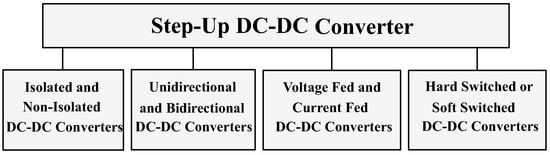
Figure 1. Categories of step-up DC-DC converters.
2.1. Isolated and Non-Isolated DC-DC Converters
Regarding the presence of galvanic isolation, DC-DC converters can be classified into isolated or non-isolated. The isolated converters are characterized for using transformers to obtain the desired voltage gain. However, the leakage inductance of the transformer windings leads to high voltage spikes on the main switch and, consequently, high switching losses.
In applications that do not demand high voltage gain or high efficiency, non-isolated converters without magnetic coupling can be a simple (since the design of the magnetic element is eliminated) and adequate solution.
There are also non-isolated DC-DC converters that use built-in transformer and/or coupled inductor. These solutions are suitable candidates to be employed in applications where high voltage gain with high efficiency and reliability are required, such as microinverters and power optimizers.
In both types of non-isolated DC-DC converters (with or without magnetic coupling), the negative terminal of the output voltage can either be connected to the negative terminal of the input voltage or be floating. However, in grid-connected PV applications where galvanic isolation is not mandatory, the first option can be used to improve system performance. In fact, it helps to reduce the leakage currents between the converter and the point of common coupling, which is grounded.
2.2. Unidirectional and Bidirectional DC-DC Converters
In most DC-DC converters, the power flow is unidirectional (from input to output). This feature is required in applications where the input source should only supply power to the load, e.g., PV modules. On the other hand, in applications that have energy storage systems, DC-DC converters with the ability to transfer energy bidirectionally must be used.
2.3. Voltage- and Current-Fed DC-DC Converters
With respect to the input filter, DC-DC converters can be classified into voltage- or current-fed. The first configuration is characterized for having a capacitive input filter while the second one has an inductive input filter. The use of an inductive input filter makes possible to attenuate the input current ripple, which is a desired feature to step-up DC-DC converters that are used in PV MICs. Furthermore, both configurations can operate with soft switching in applications with variable input voltage. Due to the characteristics described above, the current-fed DC-DC converters are very popular in PV applications, as PV modules behave as current sources.
2.4. Hard- or Soft-Switched DC-DC Converters
The DC-DC converters can operate with hard- or soft-switching. In hard-switched DC-DC converters, the currents and voltages on the semiconductors during the turn-on and turn-off transitions are different from zero, causing switching losses. For this reason, the switching frequency in these converters must be limited, which commits the goals of minimizing the size of the energy storage elements. Besides, these converters are affected by electromagnetic interference problems due to the high current and voltage variation rates.
In soft-switched DC-DC converters, the voltage on the switches falls to zero and, immediately after a short time interval—called dead time—the switches are turned on, mechanism known as “zero voltage switching” (ZVS). Furthermore, small capacitors can be added in series with the leakage inductance of the magnetic element to form resonant operation stages. In these stages, the current flowing through the diodes decreases naturally to zero before the diode becomes reverse-biased, mechanism known as “zero current switching” (ZCS).
2.5. Usual Requirements of DC-DC Converters for Microinverters
From the evaluation of the operational characteristics presented in this section, the main requirements that DC-DC converters intended for PV microinverters should meet are:
- (i) Common ground, i.e., the DC-DC converter must be non-isolated;
- (ii) High voltage gain capability, i.e., the DC-DC converter must be a step-up converter; and
- (iii) unidirectional.
It is important to point out that soft switching and resonant mechanisms can lead to reduced switching loss, which is desirable in PV microinverters.
As indicated in the requirements described above, step-up DC-DC converters are the most commonly used solution for DC-DC power conversion stage in MICs. The most common converter that belongs to this category is the conventional boost converter. However, it has several drawbacks already observed in the literature, such as its non-capability to provide high voltage gain. Thus, before presenting some step-up DC-DC converters proposed in the literature for PV applications, it is extremely important to understand how basic voltage-boosting techniques work.
References
- IRENA. Future of Solar Photovoltaic: Deployment, Investment, Technology, Grid Integration and Socio-Economic Aspects; Technical Report; A Global Energy Transformation: Paper; International Renewable Energy Agency—IRENA: Abu Dhabi, United Arab Emirates, 2019.
- Romero-Cadaval, E.; Spagnuolo, G.; Franquelo, L.G.; Ramos-Paja, C.A.; Suntio, T.; Xiao, W.M. Grid-Connected Photovoltaic Generation Plants: Components and Operation. IEEE Ind. Electron. Mag. 2013, 7, 6–20.
- Kouro, S.; Leon, J.I.; Vinnikov, D.; Franquelo, L.G. Grid-Connected Photovoltaic Systems: An Overview of Recent Research and Emerging PV Converter Technology. IEEE Ind. Electron. Mag. 2015, 9, 47–61.
- Santos de Carvalho, M.R.; Bradaschia, F.; Rodrigues Limongi, L.; de Souza Azevedo, G.M. Modeling and Control Design of the Symmetrical Interleaved Coupled-Inductor-Based Boost DC-DC Converter with Clamp Circuits. Energies 2019, 12, 3432.
- Yuan, J.; Blaabjerg, F.; Yang, Y.; Sangwongwanich, A.; Shen, Y. An Overview of Photovoltaic Microinverters: Topology, Efficiency, and Reliability. In Proceedings of the 2019 IEEE 13th International Conference on Compatibility, Power Electronics and Power Engineering (CPE-POWERENG), Sonderborg, Denmark, 23–25 April 2019; pp. 1–6.
- Pereira, A.V.C.; Cavalcanti, M.C.; Azevedo, G.M.; Bradaschia, F.; Neto, R.C.; Carvalho, M.R.S.d. A Novel Single-Switch High Step-Up DC–DC Converter with Three-Winding Coupled Inductor. Energies 2021, 14, 6288.
- Zhang, X.; Zhao, T.; Mao, W.; Tan, D.; Chang, L. Multilevel Inverters for Grid-Connected Photovoltaic Applications: Examining Emerging Trends. IEEE Power Electron. Mag. 2018, 5, 32–41.
More
Information
Subjects:
Engineering, Electrical & Electronic
Contributor
MDPI registered users' name will be linked to their SciProfiles pages. To register with us, please refer to https://encyclopedia.pub/register
:
View Times:
1.3K
Revisions:
2 times
(View History)
Update Date:
05 Jan 2022
Table of Contents


Notice
You are not a member of the advisory board for this topic. If you want to update advisory board member profile, please contact office@encyclopedia.pub.
OK
Confirm
Only members of the Encyclopedia advisory board for this topic are allowed to note entries. Would you like to become an advisory board member of the Encyclopedia?
Yes
No
${ textCharacter }/${ maxCharacter }
Submit
Cancel
Back
Comments
${ item }
|
${ item.createdUser.fullName }
${ item.createdAt }
${ item.vote }
${ item.reply }
Delete
${ reply.createdUser.fullName }
${ reply.createdAt }
${ reply.vote }
Delete
There is no reply to this comment~
${ item.replyTextCharacter }/${ item.replyMaxCharacter }
Submit
Cancel
More
No more~
There is no comment~
${ textCharacter }/${ maxCharacter }
Submit
Cancel
${ selectedItem.replyTextCharacter }/${ selectedItem.replyMaxCharacter }
Submit
Cancel
Confirm
Are you sure to Delete?
Yes
No