Your browser does not fully support modern features. Please upgrade for a smoother experience.
Submitted Successfully!
 +1 credit
Thank you for your contribution! You can also upload a video entry or images related to this topic.
For video creation, please contact our Academic Video Service.
| Version | Summary | Created by | Modification | Content Size | Created at | Operation |
|---|---|---|---|---|---|---|
| 1 | Massimo Robiony | + 2361 word(s) | 2361 | 2021-12-16 04:04:32 | | | |
| 2 | Nora Tang | + 166 word(s) | 2527 | 2021-12-16 09:30:09 | | |
Video Upload Options
We provide professional Academic Video Service to translate complex research into visually appealing presentations. Would you like to try it?
Cite
If you have any further questions, please contact Encyclopedia Editorial Office.
Robiony, M. Engineering Principles for Clinicians. Encyclopedia. Available online: https://encyclopedia.pub/entry/17189 (accessed on 25 June 2026).
Robiony M. Engineering Principles for Clinicians. Encyclopedia. Available at: https://encyclopedia.pub/entry/17189. Accessed June 25, 2026.
Robiony, Massimo. "Engineering Principles for Clinicians" Encyclopedia, https://encyclopedia.pub/entry/17189 (accessed June 25, 2026).
Robiony, M. (2021, December 16). Engineering Principles for Clinicians. In Encyclopedia. https://encyclopedia.pub/entry/17189
Robiony, Massimo. "Engineering Principles for Clinicians." Encyclopedia. Web. 16 December, 2021.
Copy Citation
As innovation and especially the advent of customized prostheses has deeply modified many surgical procedures in our discipline, it is imperative for the contemporary surgeon to become aware of the impact that the MDR will have on many aspects, including the choice of the manufacturer, the evaluation of the devices, point-of-care 3D printing labs, and medical software.
printing
three-dimensional
maxillofacial prosthesis implantation
1. Additive Manufacturing Concepts for the CMF Surgeon
Metal implants for CMF surgery are generally produced using additive manufacturing (AM) technologies that allow to 3D print a lot of metal types and especially titanium and its alloys. 3D powder bed fusion (PBF) printing is a production process that consists of the progressive deposition along the vertical axis of ultra-thin layers of metallic powder, melted layer by layer using an energy source appropriately guided depending on the desired geometry. In the case of overhanging features in respect to the growth direction of the fusion, the geometry to be printed will often need to be supported by column-shape elements that have the double function to ensure a solid base for the protruding features and to dissipate heat [1].
The most important advantage of these technologies is to allow the creation of very peculiar and complicated shapes, that could not be produced with the classic subtractive machining, like milling. For this reason, 3D PBF printing is perfectly suitable to the challenges imposed by the prosthetic replacement of the facial skeleton, since it allows the creation of prostheses that perfectly replicate even the most complicated bone anatomies.
The printing process is very delicate, it takes place in controlled atmosphere and the conformity of the produced pieces depends firstly on a correct setting of the parameters of the machine and then on a good positioning of the piece in the melting chamber as well as on an appropriate design. The most common technologies for 3D PBF printing are SLM (selective laser melting) and EBM (electron beam melting). The main difference between them is the energy source, a laser for the former and a high energy electron beam for the latter [2].
EBM vs. SLM
It is useful to understand the main properties of the technology and to be aware of its limits and criticalities while designing a piece with particular resistance, finishing or precision features to be produced with 3D printing, since SLM and EBM are different. The main differences between them are the following [1]:
-
EBM technology has usually a higher building rate in respect to the SLM, therefore it is more suitable for the production of complex shapes, for example lattice structures; EBM technology has usually a higher building rate compared to SLM. This is due to two main factors: first, layer thickness has higher values (50–100 µm in respect to the 20–100 µm of the SLM process); secondly, the immediate electron beam motion from one location to another, thanks to the instantaneous response of magnetic coils, can considerably speed up component fabrication (for example, electron beam speed can reach 8000 m/s in ARCAM machines [3], with the laser reaching 7 m/s in EOS machines [4]). For instance, in the production of truss-like structures (lattice structures), EBM is to be chosen;
-
The surface finishing of a component produced with EBM is much lower in respect to an SLM product. Is it sufficient to consider that the roughness parameters of EBM “as built” specimens are about twice those of SLM “as built” ones: in fact the roughness of EBM is 30–40 μm while for SLM specimens is 11–18 um. This is mainly due to the fact that the layer thickness, powder size, and melting pool size in the case of SLM are half the one used in EBM specimens [5];
-
The components produced with SLM undergo strong thermic gradients during the 3D printing process, since the preheating temperature of the powders is generally low, since the temperature of the chamber in SLM process is the environment temperature, assumed to be 293 K [6]. That is why they need some thermic post treatments in order to reduce the residual stresses that take origin inside the material because of the rapid and iterative phase change of the metal (solid–liquid–solid). On the contrary, in the EBM technology the temperature of the powder bed is higher and ensures the absence of thermal stresses inside the melted material, around 870 K during the melting process [7];
-
On the contrary, maintaining the powder bed at high temperature has a bad influence on the quality of the microstructure of the melted metal that results coarse with large grains. This fact has a direct influence on the mechanical characteristics of the material: an SLM component, in fact, has higher resistance to traction while being less ductile in respect to an EBM product [8][9].
-
In the EBM, the pre-heating of the powder allows the unmelted particles to bind together and to act as a support for the overhanging geometrical features. Generally, EBM products need fewer physical supports in respect to the SLM ones.
The correct positioning of the supports, especially when using the SLM, accounts for the good quality of the final piece in terms of dimensional precision, surface finishing, and defects. The main functions of support structures are [10]:
-
Withstand deformation or even collapse of processed material caused by gravity during the manufacturing process;
-
Mitigate the effects of thermal gradients generated during production, since thermal distortions may lead to cracks, curling, sag, delamination, and shrinkage;
-
Anchor the part to the build platform;
-
In PBF, they stop any layer shifting during the re-coating phase.
In summary, the SLM process requires an accurate study for the positioning of the supports and a fundamental post processing phase, in which the component is cleaned from the residual powder, the supports are removed, and the piece is thermically treated to relieve residual stresses and avoid cracking. EBM products, as seen before, do not need such a long post processing, except for a very accurate powder removing phase. Of course, rough surfaces “as built” will have a higher roughness value and might need some finishing operations to enhance their quality.
Figure 1 schematically represents SLM and EBM processes and Figure 2 illustrates CMF implants prototyped using SLM and used for surgeries.
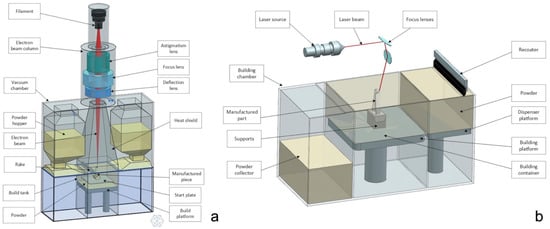
Figure 1. EBM and SLM technology principles: (a) EBM; (b) SLM.
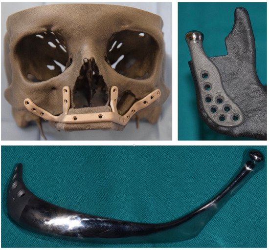
Figure 2. 3D printed implants manufactured by using SLM and used for surgeries at our institution include customized reconstruction plates, temporomandibular joint prostheses, and full mandibular prostheses used for reconstructive purposes in oncologic patients.
2. How to Evaluate the Requested CMF Implant? A Guide for the Surgeon
2.1. Principles of Mechanical Defects Formation
Before learning how to perform an effective visual inspection, it is necessary to understand some main defects connected with the 3D PBF printing. They can be divided into macroscopic and microscopic, and they usually depend on the wrong setting of the parameters of the machine, but they are even related with some criticalities of the geometry to be printed and its positioning inside the melting chamber. It is of prominent importance to underline that almost every defect can be avoided or corrected by conducting a systematic analysis and optimization of the parameters involved in the 3D printing process (Table 1).
Table 1. Criticalities that might occur during the manufacturing process and design recommendations to avoid them.
| Critical Feature Description | Recommendation for Prosthesis Design |
|---|---|
| Vertical thin walled structures with thickness from 1 to 0.1 mm | Avoid thin walled parts having thickness smaller than 0.2 mm |
| Pipe-like, hollow cylinders with different external diameters and thicknesses | |
| Small quarters of spherical shells presenting undercut surfaces | |
| Abrupt transition from semi-void section to full section | Avoid abrupt section variations whenever possible |
| Small full cross section parallelepipeds and cylinders having variable fillets/radii at their bases | It is possible to print small features with small or no fillets/radii at their conjunctions with other surfaces |
| Horizontal cylindrical holes with diameters in the range 2–8 mm, without internal supports | Horizontal holes are feasible having maximum diameter of about 8 mm, but they can be inaccurate; better results can be achieved by assuming a drop-like cross section shape |
| (Undercut) surfaces with different slope | Surface quality is affected by the staircase effect, but it can be partially improved by varying the orientation of the part with respect to the platform. Small undercut surfaces are feasible without supports |
-
Porosity: the presence of pores inside the metallic structure could be critical for the fatigue resistance of the component [11]. Notably, porosities usually represent the trigger points for cracks propagation. These pores usually measure from 1 to 20 µm and can extend up to the surface.
-
Balling: melt ball formation occurs when the molten material solidifies into spheres instead of solid layers. The result is a rough and bead-shaped surface that produces an irregular layer deposition with detrimental effects on the density and quality of the part [12]. Balling increases the surface roughness and contributes to the formation of a large number of pores.
-
Surface defects: the presence of a rough and non-homogeneous surface represents a critical issue for the final component. In PBF processes, surface roughness has two main contributors: the stair-stepping effect due to the layer-wise production, and the actual roughness of the metal surface. The surface finishing depends on the surface orientation with respect to the growth direction [13]. In particular, downward and upward surfaces are known to have considerably different roughness properties. The former present much lower surface quality. It is important to highlight the dependence of the fatigue resistance on the surface roughness of the stressed surface: the higher the roughness the lower the fatigue performance of the component.
-
Geometric defects: the PBF produced parts may exhibit different kinds of dimensional and geometric deviations from the nominal model: shrinkage and oversizing are the most common ones. Other sources of inaccuracy are represented by warping (a curling phenomenon that yields a curved profile of down facing surfaces intended to be flat) and by the formation of super elevated edges. These phenomena deteriorate the surface topology and the dimensional accuracy while interfering with the efficiency of the recoating system as well as damaging the adjacent pieces. Other distortions affect critical features like thin walls, overhanging surfaces, and acute corners [14].
-
Residual stresses, cracking, and delamination: the SLM printing is known to create in the molten components great residual stresses that could result in cracking or delamination when the arisen tensile stress exceeds the ultimate tensile strength and overcomes the binding ability between two adjacent layers [15]. As a consequence, a partial disconnection of the part from the base plate could occur.
-
Microstructural inhomogeneities and impurities: PBF processes involve highly localized high-heat inputs during very short beam-material interaction times that will therefore significantly affect the microstructure of the part [16], leading to the formation of microstructural inhomogeneities or nonequilibrium microstructures that could have a detrimental influence on the mechanical and functional performances of the part. These kinds of defects includes impurities (inclusions, contaminations from other materials, and formations of surface oxides), grain size characteristics, and crystallographic textures. Furthermore, the presence of unfused powders within pores or in the form of satellite powder clumps could represent a severe problem for the safety of the device [17].
2.2. Visual Inspection
While evaluating the conformity of components printed with 3D PBF technology, it is a good habit to keep in mind all of these defect types in order to perform an efficient visual inspection. This is especially true while evaluating a CMF component that is under assessment for surgical implantation. The leading idea is the smoother and more homogenous the surface, the better the quality of the component. It will be of key importance to evaluate the absence of isolated pores (1), detectable with bare eye, and of inhomogeneous accumulation of material, like clots (2), burrs or thin leaves of material (3), since they represent structural discontinuities, possible zones of stagnation of unmelted powders or of undesired fusion secondary products (10–150 µm). If not correctly removed, they could promote the proliferation of pathogens. Figure 3 refers to a mandibular prosthesis ordered by our institution and rejected because of unwanted defects. In this example, even a bare eye inspection, if performed with attention and according with the aforementioned explanations, reveals unacceptable imperfections.
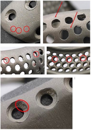
Figure 3. Example of accurate visual inspection conducted on a mandibular prosthesis ordered before MDR entered into force according to the explanations provided in Section 2.2.2. The manufacturer did not comply with requirements of the new MDR. In particular, undesired amounts of material can be seen on the edges of screw holes, appearing as plugs, clots, or thin leaves. Such imperfections are at risk of detachment during screw fixation and are freed into the body. Moreover, the whole implant surface is filled with small burrs, which are the ideal support for biofilm adhesion.
2.3. Laboratory Inspections
On the other hand, microporosity and microcracks are not detectable with a visual inspection, therefore special tests need to be carried out to observe them, as they could represent the trigger point for larger cracks especially in fatigue stressed components. Invasive and not invasive techniques could be used for this purpose. The former ones include:
-
Metallographic analysis: the component is cut in different positions and the sections are analyzed with a scanning electron microscope, SEM;
-
Penetrant liquid testing: the component is immersed in a fluorescent liquid with high capillarity and is then analyzed under a Wood lamp to see where the liquid propagated—this test highlights only surface porosities that could be critical for biological contamination. Penetrant liquid test is a non-destructive control method, nevertheless the analyzed part could undergo contamination by the fluorescent liquid [18];
whereas the latter ones include:
However, to be sure of the safety of the component, a biocompatibility panel of tests should be performed in order to understand if this kind of porosity is critical for contaminants and for bacteria proliferation.
3. Design Tips to Improve the Final Result
Porosity and geometrical defects are often the consequence of a mispositioning of the supports or of a wrong orientation of the part in the melting chamber. Therefore, while creating and designing the virtual model, it is fundamental to follow some guidelines for the 3D PBF printing, which need to respect some feasibility requirements to avoid possible issues during the production steps:
-
Identify the functional surfaces, where good finishing and precision are essential, in order for the producer to avoid their down facing positioning and to avoid placing supports on it.
-
Avoid inserting in the design undercut features, i.e., that have some surfaces overriding a critical angle of inclination in respect to the working plane. The critical angle depends on the process, on the material, and on the parameters of the machine, but generally it is known to be around 45°. Surfaces that override this inclination need to be supported and therefore could undergo a lack of quality [23].
-
If not strictly necessary, avoid the positioning of holes with a non-parallel axis in respect to the growth direction of the piece. Do not use too long bridge elements. If it is possible, position holes, pits, and through holes with the axis as closer as possible to the vertical position in order to prevent the formation of unwanted material accumulations.
-
Avoid too small holes and too thin features, that would be very affected by the residual stresses and would probably deform. If such details are necessary, they will be performed using a subtractive method once the part is printed.
References
- Gibson, I.; Rosen, D.W.; Stucker, B. Additive Manufacturing Technologies. In 3D Printing, Rapid Prototyping, and Direct Digital Manufacturing, 2nd ed.; Springer: New York, NY, USA, 2015; ISBN 978-1-4939-2113-3.
- Grasso, M.; Colosimo, B.M. Process defects andin situmonitoring methods in metal powder bed fusion: A review. Meas. Sci. Technol. 2017, 28, 044005.
- Arcam, A.B. Arcam Q20 Technical Data. 2015. Available online: www.arcam.com/wp-content/uploads/Arcam-Q20-final.pdf (accessed on 24 November 2021).
- EOS. Laser sintering system EOSINT M 280 for the production of tooling inserts, prototype parts and end products directly in metal. In The Technology: Laser Sintering—The Key to E-Manufacturing; EOS GmbH Electro Optical Systems Corporate Headquarters: Krailling/Munich, Germany, 2017.
- Vayssette, B.; Saintier, N.; Brugger, C.; El May, M. Surface roughness effect of SLM and EBM Ti-6Al-4V on multiaxial high cycle fatigue. Theor. Appl. Fract. Mech. 2020, 108, 102581.
- Ansari, M.J.; Nguyen, D.-S.; Park, H.S. Investigation of SLM Process in Terms of Temperature Distribution and Melting Pool Size: Modeling and Experimental Approaches. Materials 2019, 12, 1272.
- Gokuldoss, P.K.; Kolla, S.; Eckert, J. Additive Manufacturing Processes: Selective Laser Melting, Electron Beam Melting and Binder Jetting—Selection Guidelines. Materials 2017, 10, 672.
- Zhao, X.; Li, S.; Zhang, M.; Liu, Y.; Sercombe, T.B.; Wang, S.; Hao, Y.; Yang, R.; Murr, L.E. Comparison of the microstructures and mechanical properties of Ti–6Al–4V fabricated by selective laser melting and electron beam melting. Mater. Des. 2016, 95, 21–31.
- Koike, M.; Greer, P.; Owen, K.; Lilly, G.; Murr, L.E.; Gaytan, S.M.; Martinez, E.; Okabe, T.H. Evaluation of Titanium Alloys Fabricated Using Rapid Prototyping Technologies—Electron Beam Melting and Laser Beam Melting. Materials 2011, 4, 1776–1792.
- Jiang, J.; Xu, X.; Stringer, J. Support Structures for Additive Manufacturing: A Review. J. Manuf. Mater. Process. 2018, 2, 64.
- Edwards, P.D.; O’Conner, A.; Ramulu, M. Electron Beam Additive Manufacturing of Titanium Components: Properties and Performance. J. Manuf. Sci. Eng. 2013, 135, 061016.
- Li, R.; Liu, J.; Shi, Y.; Wang, L.; Jiang, W. Balling behavior of stainless steel and nickel powder during selective laser melting process. Int. J. Adv. Manuf. Technol. 2012, 59, 1025–1035.
- Fox, J.C.; Moylan, S.P.; Lane, B.M. Effect of Process Parameters on the Surface Roughness of Overhanging Structures in Laser Powder Bed Fusion Additive Manufacturing. Procedia CIRP 2016, 45, 131–134.
- Grasso, M.; Laguzza, V.; Semeraro, Q.; Colosimo, B.M. In-Process Monitoring of Selective Laser Melting: Spatial Detection of Defects Via Image Data Analysis. J. Manuf. Sci. Eng. 2017, 139, 051001.
- Harrison, N.J.; Todd, I.; Mumtaz, K. Reduction of micro-cracking in nickel superalloys processed by Selective Laser Melting: A fundamental alloy design approach. Acta Mater. 2015, 94, 59–68.
- Thijs, L.; Verhaeghe, F.; Craeghs, T.; Van Humbeeck, J.; Kruth, J.-P. A study of the microstructural evolution during selective laser melting of Ti–6Al–4V. Acta Mater. 2010, 58, 3303–3312.
- Smith, R.J.; Hirsch, M.; Patel, R.; Li, W.; Clare, A.T.; Sharples, S.D. Spatially resolved acoustic spectroscopy for selective laser melting. J. Mater. Proc. Technol. 2016, 236, 93–102.
- Rucka, M. Special Issue: “Non-Destructive Testing of Structures”. Materials 2020, 13, 4996.
- Turó, A.; Chávez, J.A.; García-Hernández, M.J.; Bulkai, A.; Tomek, P.; Tóth, G.; Gironés, A.; Salazar, J. Ultrasonic inspection system for powder metallurgy parts. Measurement 2013, 46, 1101–1108.
- Millon, C.; Vanhoye, A.; Obaton, A.-F.; Penot, J.-D. Development of laser ultrasonics inspection for online monitoring of additive manufacturing. Weld. World 2018, 62, 653–661.
- Taud, H.; Martinez-Angeles, R.; Parrot, J.F.; Hernandez-Escobedo, L. Porosity estimation method by X-ray computed tomography. J. Pet. Sci. Eng. 2005, 47, 209–217.
- Farber, L.; Tardos, G.; Michaels, J.N. Use of X-ray tomography to study the porosity and morphology of granules. Powder Technol. 2003, 132, 57–63.
- Badiru, A.B.; Valencia, V.V.; Liu, D. (Eds.) Additive Manufacturing Handbook: Product Development for the Defense Industry, 1st ed.; CRC Press: Boca Raton, FL, USA, 2017; ISBN 978-1-315-11910-6.
More
Information
Subjects:
Dentistry, Oral Surgery & Medicine
Contributor
MDPI registered users' name will be linked to their SciProfiles pages. To register with us, please refer to https://encyclopedia.pub/register
:
View Times:
874
Revisions:
2 times
(View History)
Update Date:
16 Dec 2021
Table of Contents


Notice
You are not a member of the advisory board for this topic. If you want to update advisory board member profile, please contact office@encyclopedia.pub.
OK
Confirm
Only members of the Encyclopedia advisory board for this topic are allowed to note entries. Would you like to become an advisory board member of the Encyclopedia?
Yes
No
${ textCharacter }/${ maxCharacter }
Submit
Cancel
Back
Comments
${ item }
|
${ item.createdUser.fullName }
${ item.createdAt }
${ item.vote }
${ item.reply }
Delete
${ reply.createdUser.fullName }
${ reply.createdAt }
${ reply.vote }
Delete
There is no reply to this comment~
${ item.replyTextCharacter }/${ item.replyMaxCharacter }
Submit
Cancel
More
No more~
There is no comment~
${ textCharacter }/${ maxCharacter }
Submit
Cancel
${ selectedItem.replyTextCharacter }/${ selectedItem.replyMaxCharacter }
Submit
Cancel
Confirm
Are you sure to Delete?
Yes
No