Your browser does not fully support modern features. Please upgrade for a smoother experience.
Submitted Successfully!
 +1 credit
Thank you for your contribution! You can also upload a video entry or images related to this topic.
For video creation, please contact our Academic Video Service.
| Version | Summary | Created by | Modification | Content Size | Created at | Operation |
|---|---|---|---|---|---|---|
| 1 | Yinghong Qin | + 2465 word(s) | 2465 | 2021-10-11 04:09:20 | | | |
| 2 | Jason Zhu | -2 word(s) | 2463 | 2021-11-15 03:32:52 | | | | |
| 3 | Jason Zhu | -2 word(s) | 2463 | 2021-11-15 03:36:07 | | |
Video Upload Options
We provide professional Academic Video Service to translate complex research into visually appealing presentations. Would you like to try it?
Cite
If you have any further questions, please contact Encyclopedia Editorial Office.
Qin, Y. Heat Transfer and Bearing Characteristics. Encyclopedia. Available online: https://encyclopedia.pub/entry/15960 (accessed on 24 July 2026).
Qin Y. Heat Transfer and Bearing Characteristics. Encyclopedia. Available at: https://encyclopedia.pub/entry/15960. Accessed July 24, 2026.
Qin, Yinghong. "Heat Transfer and Bearing Characteristics" Encyclopedia, https://encyclopedia.pub/entry/15960 (accessed July 24, 2026).
Qin, Y. (2021, November 13). Heat Transfer and Bearing Characteristics. In Encyclopedia. https://encyclopedia.pub/entry/15960
Qin, Yinghong. "Heat Transfer and Bearing Characteristics." Encyclopedia. Web. 13 November, 2021.
Copy Citation
Energy piles are commonly frictional piles that are subject to lateral frictional resistance and tip resistance balanced with external forces. To simplify the model, an energy pile is usually assumed to be a rod that deforms thermally. Energy piles are subjected to thermal and mechanical stresses simultaneously.
ground source heat pumps
energy piles
heat transfer
bearing capacity
1. Introduction
Traditional fossil fuels such as coal, oil, and natural gas account for most of the energy share. However, these fuels produce large amounts of harmful gases, causing serious environmental pollution. Research on clean energy technologies has received extensive attention to solve this serious problem, and shallow geothermal energy has been advocated as a kind of typical clean energy because of its characteristics of large reserves, wide distribution, and non-polluting. Ground source heat pumps (GSHP) are the main way to utilize shallow geothermal energy and have been widely used in many countries such as South Korea [1], Japan [2], and others [3]. Vertical and horizontal layouts are the two forms of GSHP, in which the horizontal layout requires a large construction area but the vertical one is costly due to borehole drilling. Considering these two shortcomings, energy piles that embed the geothermal heat exchanger in the pile foundation of the building structure offer a new idea for the promotion of GSHP and simultaneously meet the load-bearing and heat exchange requirements. Energy piles are gradually being used in tunnels [4], bridges [5], and other fields [6][7]. As shown in Figure 1, GSHP consists of a main circuit buried in the piles and a secondary circuit in the upper building, both of which are connected by a heat pump to transfer shallow heat energy to upper buildings [8].
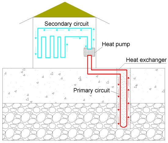
Figure 1. Schematic diagram of ground source heat pumps (GSHP).
Many studies involved in the introduction and analysis of heat transfer for GSHP have been documented. Noorollahi reviewed the previous research and investigations on different ground heat exchanger parameters and their effects [9]. Abuel-Naga investigated the knowledge on the design of energy piles in terms of the geo-structural and heat exchanger functions by [10]. In another study, Fadejev reviewed of available scientific literature, design standards, and guidelines on energy piles [11]. Then, Mohamad explained the knowledge about the thermal and thermo-mechanical behaviors of energy piles [12]. Their works, however, do not address the operational mechanism and optimization of energy piles under thermal-mechanical interactions. The research on energy piles has mainly focused on the heat transfer and bearing characteristics. Heat transfer accompanies heat conduction and heat convection, varying the temperature of the piles and of their surrounding soils. Correspondingly, temperature stresses develop and thus affect the bearing capacity of energy piles. This study systematically summarizes the influencing factors involved in the heat transfer process of energy piles, further presents the heat transfer models adapted to simulate the pile’s performance; then analyzes the structure’s response under temperature loads and proposes a kind of composite energy pile with potential application. The limitations of current research and future research are finally highlighted.
2. Factors Influencing Heat Transfer Performance
2.1. Heat Transfer between Fluid and Tubes
Heat exchange rate H=Cm˙ΔT W, and relative heat exchange rate
 QR=QH/W/m, are usually used to evaluate the heat transfer performance. Heat exchange rate QH represents the amount of heat transfer between energy piles and soil around the piles over a limited time. The relative heat exchange rate QR
H=Cm˙ΔT W, and relative heat exchange rate QR=QH/W/m, are usually used to evaluate the heat transfer performance. Heat exchange rate QH represents the amount of heat transfer between energy piles and soil around the piles over a limited time. The relative heat exchange rate QRrepresents the amount of heat transfer per length of tubes and is an index to evaluate the efficiency of heat transfer.
The principle for designing a tube shape is to maximize the area of heat transfer. As shown in Figure 2, the tube shapes include U-shaped, 2U-shaped, 3U-shaped, W-shaped, and S-shaped (spiral-shaped). Their heat performances are illustrated in Table 1. The S-shaped tube has the best heat transfer efficiency because it has the largest heat transfer area [13], shown in Table 1. Furthermore, the selection of tube shapes needs to consider the heat exchange rate, cost, and other factors such as the number of piles, the length of the drilling holes, and the difficulty of construction.
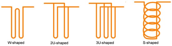
Figure 2. The shapes of heat exchange tubes.
Table 1. Comparison of heat transfer performance of different tube shapes.
| Reference | Tube Shape | Consideration | Methods | Performance Comparison |
|---|---|---|---|---|
| Jalaluddin [14] | U-shaped, 2U-shaped, 3U-shaped | Ground temperature, wall temperature, velocity of fluid | Thermal response experiment | 2U-shaped > 3U-shaped > U-shaped |
| Florides [15][16] | U-shaped, 2U-shaped | Pipe size, soil thermal conductivity, soil stratification, cost | Numerical Simulation | 2U-shaped > U-shaped |
| Gao [17][18] | U-shaped, 2U-shaped, 3U-shaped, W-shaped | Circulating medium flow, inlet temperature, the unbalanced load of cold and heat, ground temperature | Thermal response experiment and numerical simulation | High flow: 2U-shaped > W-shaped > 3U-shaped > U-shaped Low flow: W-shaped > 2U-shaped > 3U-shaped > U-shaped |
| Zarrella [19] | 3U-shaped, S- shaped | helical pitch | Equivalent Circuit | S-shaped > 3U-shaped |
| Zarrella [20] | 2U-shaped, S-shaped | Axial heat conduction, drilling length, long-term and short-term heat transfer performance | Equivalent Circuit | S-shaped > 2U-shaped |
| Yoon [13] | W-shaped, S-shaped | The intermittent operation, cost, number of piles | Thermal response test and numerical simulation | S-shaped > W-shaped |
| Luo [21] | 2U-shaped, 3U-shaped, 2W-shaped, S-shaped | The intermittent operation, pipe size, cost | Thermal response test and numerical simulation | 3U-shaped > 2W-shaped, S-shaped > 2U-shaped |
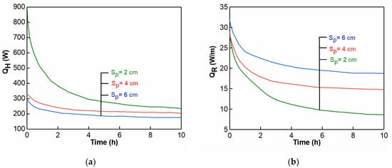
For S-shaped tubes, spiral pitches, are proportional to the heat exchange area. By conducting a thermal performance test using tubes with a pitch of 200 mm and 500 mm, it was found that the heat exchange rate increased with the decrease of the pitch [22]. Figure 3 shows the variation ofQand QRunder different pitches. The heat flow between the tubes interacts in the case of small pitches, reducing the relative heat exchange rate [23][24]. To subside the interaction, some scholars proposed to add an insulation layer around the fluid outlet [25]. The length of the insulation layer is different for variable operation modes.
Temperature (determined by atmospheric temperature) and velocity of inlet fluid are positively related to the efficiency of heat transfer. The inlet temperature directly affects the temperature difference between the inlet and outlet liquid. According to existing studies [17][18], the heat exchange rate QH
approximately increases linearly with the inlet temperature within a certain temperature range. In addition, high-speed fluid maintains turbulent state, improving the heat exchange rate effectively [26].
The improper arrangement of heat transfer tubes and pile spacing induces thermal interference phenomenon. Furthermore, the quantitative research on their influence of heat transfer efficiency still needs to be explored. The production factors, such as the cost, structural safety, and others, should be considered during design.
The durability of heat exchanger tube material is a subject of concern. The tubes may be damaged by the corrosion of the circulating medium during the cyclic heat transfer. The heat transfer efficiency, load capacity, and durability of energy piles are reduced by damaged tubes. To solve this problem, the maintenance and replacement technology of the tubes must be developed.
2.2. Effects of Materials and Geometry on Heat Transfer
Geometric properties significantly affect the heat transfer performance of energy piles, such as thermal conductivity of concrete, pile length, pile diameter, and others. The heat transfer performance of concrete is evaluated by the thermal conductivity. Studies have shown that the heat exchange rate increases by 42% when the thermal conductivity increases from 1.2 to 2.5 W/(m K) [27]. The thermal conductivity of concrete can be increased by adding admixtures such as steel fiber and graphite. Increasing the pile’s length and diameter can also enlarge the heat transfer area, improving the heat transfer rate [26][27]. Factors including the heat transfer, bearing characteristics, and cost of a pile must be therefore considered in the design.
2.3. Heat Transfer Performance of Soils
2.3.1. Water Content
The pore structure of the soil around the energy piles changes after it is filled by water, varying heat conduction and transfer performance accordingly. Generally, increasing the water content can enlarge the heat storage and heat transfer capacity [28]. When the water content is low, the surface of soil particles is covered with a water film, having little effect on the thermal conductivity [29]; as the water content increases, a “water bridge” forms between soil particles. The thermal conductivity of water is much larger than that of air, resulting in a significant increase in the thermal conductivity of soil [28][30].
2.3.2. Mineral Composition and Dry Density
The thermal conductivity of soil particles can be analyzed through composition and dry density [31]. For different soil minerals, the thermal conductivity is significantly different. The thermal conductivity of quartz is about 7~9 W/(m K), while the thermal conductivity of mica, kaolinite, and feldspar is about 2~3 W/(m K). To quantify the thermal conductivity of soil composed of various mineral components, past studies suggested that the minerals can be divided into quartz and others, then the thermal conductivity of mixed soils can be determined by the quartz content (20% volume fraction as the limit) [32]. However, the calculated thermal conductivity of the same mineral may be different because the impure texture, dry density, and measurement methods are different.
Gases exist in the pores mainly in a free state, while a small part of gases are adsorbed/dissolved on the surface of soil particles. Factors such as shape, structure, and arrangement of soil particles determine the porosity, size, and distribution of soil pores, affecting the thermal conductivity [33][34]. As shown in Figure 4, there is a positive correlation between dry density and thermal conductivity of the soils because the contact area of soil particles increases with the increase of dry density, and the thermal conductivity of mixed soils is closer to the particles [35][36]. The microstructure of soils will also have an influence on the thermal conductivity, and perfect grading has greater thermal conductivity [33][37]. Additionally, previous works showed that the disturbance of the soils have little influence on the thermal conductivity, therefore field tests can be used instead of indoor ones [38].
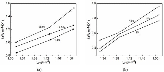
Figure 4. Relationship between thermal conductivity and dry density of soil with different water contents, (a) sand; (b) clay.
2.4. Long-Term Service
Within about 10 m under the ground surface, the temperature periodically fluctuates daily and seasonally. Below 10 m depth, the temperature remains relatively constant, which is conducive to continuous heat exchange [39]. In summer, the average temperature of the shallow ground surface is lower than the air temperature and thus the surface buildings can be cooled down. In contrast, the ground temperature in winter is higher than the air temperature, and heat stored underground in summer can be harvested for building heating. However, cooling/heating demand varies seasonally. The heat around energy piles can be correspondingly accumulated or dissipated, leading to the imbalance of soil temperature and further affecting the subsequent periodic thermal cycle [40]. Such an imbalance can be alleviated by integrating solar collectors/cooling equipment to GSHP to compensate for the ground temperature [41] but the costs and long-term performance of this integral have yet to be proven.
Energy piles are mainly adapted in lower buildings and are mostly designed for 5~30 m in length. Heat transfer is concentrated in a certain depth, so the heat transfer range is limited. In most of cold regions, such as Europe and North America, GHSP is successfully used because the temperature where the energy piles are located differs greatly from the atmospheric temperature. The cost of energy piles in warm zones needs to be studied further.
Duration of long-term heat transfer is an urgent issue for energy piles. Seasonal load (unbalanced ground temperature) is the main factor affecting the long-term heat transfer performance of energy piles. In areas where groundwater is rich, the groundwater flow can significantly alleviate the unbalanced ground temperature, while in groundwater-free areas, heat compensation to the soil layer is required but effective forms of the compensation have yet to be designed and improved.
3. Numerical Simulations of GSHP Heat Transfer
In the linear heat source model, the heat transfer process is simplified to a linear and radiating heat flow, and the following assumptions are made [42]: (1) Initial geotechnical temperature is uniform; (2) heat flow is considered to transfer radially and to be constant; (3) geotechnical material is homogeneous and isotropic. The linear heat source model can be categorized into an infinite line heat source model and a finite line heat source model [43]. The solution of an infinite line heat source model is not accurate under long-term conditions, so a finite line heat source model was proposed. The detailed mathematical expressions of each model based on various shapes can be found in Appendix A.
Hollow and solid shapes are two types of cylindrical heat sources [44][45]. The solid cylindrical heat source model is used in S-shaped piles with large diameter and shallow drilling depth. Based on the classical heat source method, Man [44] proposed 1-D and 2-D heat sources for solid cylinders to consider the effect of the geometry of piles. The 1-D method does not consider the heat transfer in the axial direction. For the 2-D method, the finite heat source and surface boundary temperature are considered.
Groundwater is beneficial to enhance the heat transfer efficiency of the energy piles. Water under the groundwater table moves between the particles of the soil layers, creating horizontal flow that alleviates the heat accumulation. Traditional numerical methods based on steady-state are not appropriate to evaluate the transient process with groundwater. While some models for energy piles combined groundwater have been reported, the accurate evaluation of the heat transfer conditions remains unsolved [46][47][48][49][50][51][52][53].
Compared to vertical GSHP, in the line heat source model and cylindrical heat source model, the characteristics of the energy piles are as follows: (1) The buried depth is small, so the ground temperature boundary cannot be ignored; (2) heat transfer of concrete is significant because of the large pile diameter; (3) for a large range of heat transfer, the thermal properties of soils are time dependent. To simplify analysis, these differences are often ignored. The applicable conditions of the above three models are noted in Table 2; it is known that they do not have high adaptability as many parameters are inconsistent in complex environments. In order to get accurate results in a simple way, the models need to be selected regarding the specific application included for the geometric characteristics of the energy piles and the difference in thermal properties of concrete and soil. In the water-rich rock layer, due to groundwater flow thermal convection can mitigate heat accumulation induced by energy piles. However, such a situation is still too complicated to be simulated because of the complex transient coupling for groundwater. Another challenge is that accurate hydrogeological information cannot be obtained due to the high cost and operational difficulties.
Table 2. Applicability evaluation of main heat transfer models of energy piles.
| Model | Consideration | Inconsideration | Condition |
|---|---|---|---|
| line heat source model | Radial heat transfer | Geometry, internal heat transfer, tube shape | Constant heat flow, steady state |
| Hollow cylindrical heat source model | Geometry, thermal resistance | Geometry, thermal interference between tubes | Small diameter of piles, steady state |
| Solid cylindrical heat source model | The transient heat transfer | Thermal properties of concrete and soils | S-shaped tubes |
References
- Loveridge, F.; Mccartney, J.S.; Narsilio, G.A.; Sanchez, M. Energy geostructures: A review of analysis approaches, in situ testing and model scale experiments. Geomech. Energy Environ. 2020, 22, 100173.
- Hamada, Y.; Saitoh, H.; Nakamura, M.; Kubota, H.; Ochifuji, K. Field performance of an energy pile system for space heating. Energy Build. 2006, 39, 517–524.
- Liu, H.; Maghoul, P.; Bahari, A.; Kavgic, M. Feasibility study of snow melting system for bridge decks using geothermal energy piles integrated with heat pump in Canada. Renew. Energy. 2019, 136, 1266–1280.
- Bidarmaghz, A.; Narsilio, G.A. Heat exchange mechanisms in energy tunnel systems. Géoméch. Energy Environ. 2018, 16, 83–95.
- Kong, G.; Wu, D.; Liu, H.; Laloui, L.; Cheng, X.; Zhu, X. Performance of a geothermal energy deicing system for bridge deck using a pile heat exchanger. Int. J. Energy Res. 2018, 43, 596–603.
- Buhmann, P.; Moormann, C.; Westrich, B.; Pralle, N.; Friedemann, W. Tunnel geothermics—A German experience with renewable energy concepts in tunnel projects. Géoméch. Energy Environ. 2016, 8, 1–7.
- Lai, J.; Wang, X.; Qiu, J.; Zhang, G.; Chen, J.; Xie, Y.; Luo, Y. A state-of-the-art review of sustainable energy based freeze proof technology for cold-region tunnels in China. Renew. Sustain. Energy Rev. 2018, 82, 3554–3569.
- Preene, M.; Powrie, W. Ground energy systems: From analysis to geotechnical design. Géotechnique 2009, 59, 261–271.
- Noorollahi, Y.; Saeidi, R.; Mohammadi, M.; Amiri, A.; Hosseinzadeh, M. The effects of ground heat exchanger parameters changes on geothermal heat pump performance—A review. Appl. Therm. Eng. 2018, 129, 1645–1658.
- Abuel-Naga, H.; Raouf, M.I.N.; Raouf, A.M.I.; Nasser, A.G. Energy piles: Current state of knowledge and design challenges. Environ. Geotech. 2015, 2, 195–210.
- Fadejev, J.; Simson, R.; Kurnitski, J.; Haghighat, F. A review on energy piles design, sizing and modelling. Energy 2017, 122, 390–407.
- Mohamad, Z.; Fardoun, F.; Meftah, F. A review on energy piles design, evaluation, and optimization. J. Clean. Prod. 2021, 292, 125802.
- Yoon, S.; Lee, S.-R.; Xue, J.; Zosseder, K.; Go, G.-H.; Park, H. Evaluation of the thermal efficiency and a cost analysis of different types of ground heat exchangers in energy piles. Energy Convers. Manag. 2015, 105, 393–402.
- Miyara, A.; Tsubaki, K.; Inoue, S.; Yoshida, K. Experimental study of several types of ground heat exchanger using a steel pile foundation. Renew. Energy 2011, 36, 764–771.
- Florides, G.; Christodoulides, P.; Pouloupatis, P. An analysis of heat flow through a borehole heat exchanger validated model. Appl. Energy 2012, 92, 523–533.
- Florides, G.A.; Christodoulides, P.; Pouloupatis, P. Single and double U-tube ground heat exchangers in multiple-layer substrates. Appl. Energy 2013, 102, 364–373.
- Gao, J.; Zhang, X.; Liu, J.; Li, K.; Yang, J. Numerical and experimental assessment of thermal performance of vertical energy piles: An application. Appl. Energy 2008, 85, 901–910.
- Gao, J.; Zhang, X.; Liu, J.; Li, K.S.; Yang, J. Thermal performance and ground temperature of vertical pile-foundation heat exchangers: A case study. Appl. Therm. Eng. 2008, 28, 2295–2304.
- Zarrella, A.; De Carli, M.; Galgaro, A. Thermal performance of two types of energy foundation pile: Helical pipe and triple U-tube. Appl. Therm. Eng. 2013, 61, 301–310.
- Zarrella, A.; Capozza, A.; Carli, M.D. Analysis of short helical and double U-tube borehole heat exchangers: A simulation-based comparison. Appl. Energy 2013, 112, 358–370.
- Luo, J.; Zhao, H.; Gui, S.; Xiang, W.; Rohn, J.; Blum, P. Thermo-economic analysis of four different types of ground heat exchangers in energy piles. Appl. Therm. Eng. 2016, 108, 11–19.
- Park, S.; Lee, D.; Choi, H.-J.; Jung, K.; Choi, H. Relative constructability and thermal performance of cast-in-place concrete energy pile: Coil-type GHEX (ground heat exchanger). Energy 2015, 81, 56–66.
- Yang, W.; Lu, P.; Chen, Y. Laboratory investigations of the thermal performance of an energy pile with spiral coil ground heat exchanger. Energy Build. 2016, 128, 491–502.
- You, T.; Li, X.; Cao, S.; Yang, H. Soil thermal imbalance of ground source heat pump systems with spiral-coil energy pile groups under seepage conditions and various influential factors. Energy Convers. Manag. 2018, 178, 123–136.
- Li, X.-Y.; Li, T.-Y.; Qu, D.-Q.; Yu, J.-W. A new solution for thermal interference of vertical U-tube ground heat exchanger for cold area in China. Geothermics 2017, 65, 72–80.
- Cecinato, F.; Loveridge, F. Influences on the thermal efficiency of energy piles. Energy 2015, 82, 1021–1033.
- Carotenuto, A.; Marotta, P.; Massarotti, N.; Mauro, A.; Normino, G. Energy piles for ground source heat pump applications: Comparison of heat transfer performance for different design and operating parameters. Appl. Therm. Eng. 2017, 124, 1492–1504.
- Su, T.; Liu., T.; Li., X.; Yu, J.; Xiao, L. Test and analysis of thermal properties of soil in Nanjing district. Chin. J. Rock Mech. Eng. 2006, 25, 1278–1283.
- Leong, W.H.; Tarnawski, V.R.; Aittomäki, A. Effect of soil type and moisture content on ground heat pump performance. Int. J. Refrig. 1998, 21, 595–606.
- Liu, C.; Zhou, D.; Wu, H. Measurement and prediction of temperature effects of thermal conductivity of soils. Chin. J. Geotech. Eng. 2011, 33, 1877–1886.
- Barry-Macaulay, D.; Bouazza, A.; Singh, R.M.; Wang, B.; Ranjith, P. Thermal conductivity of soils and rocks from the Melbourne (Australia) region. Eng. Geol. 2013, 164, 131–138.
- Zhang, N.; Xia, S.; Hou, X.; Wang, Z. Review on soil thermal conductivity and prediction model. Rock Soil Mech. 2016, 37, 1550–1562.
- Cai, S.; Zhang, B.; Cui, T.; Guo, H.; Huxford, J. Mesoscopic study of the effective thermal conductivity of dry and moist soil. Int. J. Refrig. 2018, 98, 171–181.
- Smits, K.M.; Sakaki, T.; Limsuwat, A.; Illangasekare, T. Thermal Conductivity of Sands under Varying Moisture and Porosity in Drainage–Wetting Cycles. Vadose Zone J. 2010, 9, 172–180.
- Abu-Hamdeh, N.H.; Reeder, R.C. Soil Thermal Conductivity: Effects of Density, Moisture, Salt Concentration, and Organic Matter. Soil Sci. Soc. Am. J. 2000, 64, 1285–1290.
- Becker, B.R.; Misra, A.; Fricke, B. Development of correlations for soil thermal conductivity. Int. Commun. Heat Mass Transf. 1992, 19, 59–68.
- Angelotti, A.; Alberti, L.; La Licata, I.; Antelmi, M. Energy performance and thermal impact of a Borehole Heat Exchanger in a sandy aquifer: Influence of the groundwater velocity. Energy Convers. Manag. 2013, 77, 700–708.
- Zhang, Y.-J.; Yu, Z.-W.; Huang, R.; Wu, G.; Hu, J.-H. Measurement of thermal conductivity and temperature effect of geotechnical materials. Chin. J. Geotech. Eng. 2009, 31, 213–217.
- Florides, G.A.; Kalogirou, S.A. Annual ground temperature measurements at various depths. In Proceedings of the CLIMA 2005, Lausanne, Switzerland, 9–12 October 2005.
- Bidarmaghz, A.; Narsilio, G.A.; Johnston, I.W.; Colls, S. The importance of surface air temperature fluctuations on long-term performance of vertical ground heat exchangers. Géoméch. Energy Environ. 2016, 6, 35–44.
- Faizal, M.; Bouazza, A.; Wuttke, F.; Bauer, S.; Sanchez, M. Effect of forced thermal recharging on the thermal behaviour of a field scale geothermal energy pile. In Proceedings of the International Conference on Energy Geotechnics (ICEGT 2016), Kiel, Germany, 29–31 August 2016; Wuttke, F., Bauer, S., Sánchez, M., Eds.; CRC Press: Boca Rotan, FL, USA; pp. 557–568.
- Park, S.; Lee, S.; Oh, K.; Kim, D.; Choi, H. Engineering chart for thermal performance of cast-in-place energy pile considering thermal resistance. Appl. Therm. Eng. 2018, 130, 899–921.
- Zeng, H.Y.; Diao, N.R.; Fang, Z.H. A finite line-source model for boreholes in geothermal heat exchangers. Heat Transfer-Asian Res. 2002, 31, 558–567.
- Man, Y.; Yang, H.; Diao, N.; Liu, J.; Fang, Z. A new model and analytical solutions for borehole and pile ground heat exchangers. Int. J. Heat Mass Transf. 2010, 53, 2593–2601.
- Wang, Z.; Shao, W.; Zhang, Y. Cylindrical surface model of ground source heat pump considering soil stratification. J. Zhejiang Univ. (Eng. Sci.) 2013, 47, 1338–1345.
- Adinolfi, M.; Maiorano, R.M.S.; Mauro, A.; Massarotti, N.; Aversa, S. On the influence of thermal cycles on the yearly performance of an energy pile. Géoméch. Energy Environ. 2018, 16, 32–44.
- Diao, N.; Li, Q.; Fang, Z. Heat transfer in ground heat exchangers with groundwater advection. Int. J. Therm. Sci. 2004, 43, 1203–1211.
- Fan, R.; Jiang, Y.; Yao, Y.; Shiming, D.; Ma, Z. A study on the performance of a geothermal heat exchanger under coupled heat conduction and groundwater advection. Energy 2007, 32, 2199–2209.
- Molina-Giraldo, N.; Blum, P.; Zhu, K.; Bayer, P.; Fang, Z. A moving finite line source model to simulate borehole heat exchangers with groundwater advection. Int. J. Therm. Sci. 2011, 50, 2506–2513.
- Lee, C.K.; Lam, H. A modified multi-ground-layer model for borehole ground heat exchangers with an inhomogeneous groundwater flow. Energy 2012, 47, 378–387.
- Rivera, J.A.; Blum, P.; Bayer, P. Analytical simulation of groundwater flow and land surface effects on thermal plumes of borehole heat exchangers. Appl. Energy 2015, 146, 421–433.
- Hu, J. An improved analytical model for vertical borehole ground heat exchanger with multiple-layer substrates and groundwater flow. Appl. Energy 2017, 202, 537–549.
- Zhang, W.; Zhang, L.; Cui, P.; Gao, Y.; Liu, J.; Yu, M. The influence of groundwater seepage on the performance of ground source heat pump system with energy pile. Appl. Therm. Eng. 2019, 162, 114217.
More
Information
Subjects:
Engineering, Civil
Contributor
MDPI registered users' name will be linked to their SciProfiles pages. To register with us, please refer to https://encyclopedia.pub/register
:
View Times:
1.0K
Revisions:
3 times
(View History)
Update Date:
15 Nov 2021
Table of Contents


Notice
You are not a member of the advisory board for this topic. If you want to update advisory board member profile, please contact office@encyclopedia.pub.
OK
Confirm
Only members of the Encyclopedia advisory board for this topic are allowed to note entries. Would you like to become an advisory board member of the Encyclopedia?
Yes
No
${ textCharacter }/${ maxCharacter }
Submit
Cancel
Back
Comments
${ item }
|
${ item.createdUser.fullName }
${ item.createdAt }
${ item.vote }
${ item.reply }
Delete
${ reply.createdUser.fullName }
${ reply.createdAt }
${ reply.vote }
Delete
There is no reply to this comment~
${ item.replyTextCharacter }/${ item.replyMaxCharacter }
Submit
Cancel
More
No more~
There is no comment~
${ textCharacter }/${ maxCharacter }
Submit
Cancel
${ selectedItem.replyTextCharacter }/${ selectedItem.replyMaxCharacter }
Submit
Cancel
Confirm
Are you sure to Delete?
Yes
No