1. Spectrophotometer
A spectrophotometer allows continuous measurement of spectral reflectance over the range of interest—that is, the amount of radiation reflected at each wavelength, whatever its source is. The range of interest for solar radiation is between 300 nm and 2500 nm. The distribution of spectral reflectance over this range, in which 99% of solar radiation falls, is often referred to as the solar reflectance spectrum. Spectral reflectivity, or even reflectivity alone, is sometimes used synonymously with spectral reflectance. However, the National Institute of Standards and Technology (NIST, at the time the National Bureau of Standards, NBS) recommended reserving the ending ‘-ivity’ for radiative properties of pure and perfectly smooth materials, and to use the ending ‘-ance’ for rough and contaminated surfaces
[1]. Built-up surfaces clearly fall into the latter category. The reflectance spectrum can also be expressed using frequency rather than wavelength, as their product is a constant, equal to the velocity of light in the air. However, it is common in the field of building energy to refer to wavelength.
The solar reflectance
ρsol is calculated by averaging over the range of interest the measured spectral reflectance
ρλ, weighted by the sun spectral irradiance at the earth surface
Isol,λ (W/(m
2nm)):
Isol,λ is the amount of solar radiation at the considered wavelength λ (nm) that passes through the atmosphere and reaches the earth surface.
A spectrophotometer is an instrument that measures light. It is a complete system including a light source, a means to collect radiation that has interacted with the tested sample, and a spectrometer sensor to measure that radiation. Light is not limited to the visible range but is more widely understood as electromagnetic radiation. The term “photo” indicates that the instrument quantitatively measures radiation intensity with wavelengths. In the common ‘scanning spectrophotometer’, a monochromator containing a diffraction grating is scanned stepwise so that radiation intensity is measured at each wavelength step. In the single-beam spectrophotometer, the spectral reflectance is determined comparing the radiation intensities measured after and before the tested sample is substituted to a reference sample. In the double-beam spectrophotometer, the spectral reflectance is determined comparing the radiation intensities between two light paths—one containing the test sample and the other a reference sample. Double beams are more complex than single beams but are less sensitive to fluctuations in the light source. Reference materials for solar reflectance measurements are magnesium oxide (MgO), barium sulfate (BaSO
4) and various proprietary types of polytetrafluoroethylene (PTFE), such as the widely used Spectralon
[2]. All of these are diffuse reflectance materials with a high spectral reflectance over the entire range of solar radiation.
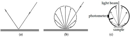
A real surface has a behavior somewhere between a specular reflector, which reflects light beams with the same angle of incidence (Figure 1a), and a diffuse reflector, which reflects in all directions (Figure 1b). A polished metal is an almost perfect specular reflector, while most built-up surfaces are rough and non-metallic—thus showing an almost diffuse behavior. In solar reflectance measurements aimed at providing data for energy balances of urban surfaces, the hemispherically reflected radiation (i.e., directly and diffusely refleted) must be detected. This is achieved by means of an integrating sphere (Figure 1c)—a component of the spectrophotometer consisting of a hollow spherical cavity with its inner surface covered with a diffuse reflective coating, typically of the same materials as the reference samples (MgO, BaSO4, PTFE). Radiation reflected by the tested sample to any point of the cavity surface is distributed equally by multiple scattering reflections to all other points, including the part covered by the photometer detector. The larger the diameter of the integrating sphere, the larger the allowed size of the sample port and the sample itself.
Figure 1. Specular reflector (a), diffuse reflector (b), and integrating sphere (c).
ASTM E903
[3] is a widely appreciated standard test method that relies upon the use of a spectrophotometer with an integrating sphere to measure the spectral reflectance of the test sample over the entire range from 300 nm to 2500 nm. The first version of the standard dates back to 1996 and was implemented into the CRRC rating program in 1998. Entering into details, it is used to measure near normal-hemispherical solar reflectance, i.e., reflectance with irradiance almost normal to the sample surface and flux leaving the surface collected, in order to detect the radiation intensity, over an entire hemisphere. A double-beam spectrophotometer is recommended, as well as an integrating sphere with a minimum diameter of 150 mm. The acquired spectrum of solar reflectance is finally averaged over the measurement range, being weighted by a spectrum of solar irradiance at the earth surface according to Equation (1). Some solar spectra are provided in previous studies
[3]; nevertheless, the choice of the reference spectrum is not so obvious.
The solar spectral irradiance depends on the position of the sun in the sky and, therefore, on the latitude, the time of the year and the time of day. It also depends on the solid angle it comes from, distinguishing between:
- - beam normal or direct normal, i.e., the solar flux coming from a solid angle covering the sun’s disk and reaching a surface perpendicular to the axis of the above-mentioned solid angle;
- - direct—from the sun’s disk onto a surface with a given inclination and orientation;
- - direct and circumsolar—which includes the direct radiation scattered by the atmosphere so that it seems to come from an area of the sky immediately adjacent to the sun’s disk, whose aperture is related to the aerosol optical depth [36];
- - diffuse—over the entire hemisphere facing the earth surface (excluded direct); and
- - global—which includes direct and diffuse.
The fraction of extraterrestrial radiation that reaches the earth surface is affected by the air mass, i.e., the mass of atmospheric air in the observer–sun path divided by the mass of atmospheric air that would be present if the observer was at sea level, at standard atmospheric pressure, and the sun was directly overhead (with air mass = 1 assigned to such a path). It is also affected by the content of water vapor in the atmosphere and the content of particle suspensions such as fog, clouds, particulate, and dust. Finally, the intensity of radiation reaching a built-up surface depends on the orientation and inclination of such a surface.
The sensitivity of the weighted radiative properties to different solar irradiance spectra was already investigated in the eighties of the past century, leading to the recommendation of a single solar spectrum for use as a standard
[4]. A spectrum used in the U.S. for various purposes was specified in the ASTM E891 standard
[5], whose first release dates back to 1987. This is the one initially recommended by ASTM E903 in its 1996 version, and it was therefore adopted by the Cool Roof Rating Council. It is specified for air mass 1.5, beam normal solar irradiance and hazy sky at the latitude of the U.S. It was probably intended for sun-tracking photovoltaic panels, so it may be a less appropriate choice while considering the thermal behavior of a built-up surface irradiated by the sun. Moreover, it was withdrawn and the current ASTM E903 version recommends data reported in the ASTM G173 standard
[6] for air mass 1.5 and direct normal radiation (including circumsolar radiation in a solid angle centered on the sun’s disk and with an aperture half-angle of 2.9°), or for global radiation on a 37° tilt south-facing surface. These spectra also seem aimed at the analysis of photovoltaic panels, respectively sun tracking or fixed—again at the latitude of the U.S. More recently, the air mass 1 global horizontal spectrum (AM1GH) has been recommended
[7][8]. It comprises both direct and diffuse radiation on a horizontal surface, with the sun directly overhead in a clear sky. The use of AM1GH allows the measuring of solar reflectance under conditions closer to the annual peak of solar heat gain, from which air conditioning systems are typically sized in terms of peak cooling load. Moreover, peak load of the electric grid and health issues mostly arise for the peak cooling load. AM1GH was also shown to apply well not only to horizontal surfaces at the latitude of the U.S., but also to moderately pitched roofs, and it is expected to work well between 49° S and 49° N
[7]. In the EU, a similar spectrum for air mass 1 is indeed specified in EN 410
[9] for analysis of glazed elements.
Table 1 summarizes the percent energy content of the previously mentioned solar spectra in the ultraviolet (UV), visible (Vis, commonly set between 400 nm and 700 nm for analyses on solar reflective materials), and near-infrared (NIR) ranges. A clearly varying spectral content is evident. In particular, the air mass 1.5 beam normal spectrum from ASTM E891 has a NIR content as high as 58%, whereas the NIR content is slightly below 50% for air mass 1 global horizontal spectra such as AM1GH, and that in EN 410. As a result, a ‘selective’ material that is highly absorbing in the visible range, e.g., due to a dark color mandatory for the considered surface, but at the same time highly reflective in the NIR range, would be rated differently because of the selected reference spectrum. Absolute discrepancy in solar reflectance measurements on a set of samples with different colors was found to be as high as 0.02 on a reflectance scale from 0 to 1
[10]—an amount scarcely relevant for energy balances, but more significant for the comparison of competing solar reflective products. Fairness of comparison is the very reason why the Cool Roof Rating Council still prescribes or recommends, for product rating, the use of the beam normal spectrum from ASTM E891
[11][12], in conjunction with both ASTM E903 and another widely used standard test method specified in ASTM C1549
[13], illustrated in the next section. The same approach is followed
[14] by the European Cool Roofs Council.
Table 1. Energy content of alternative solar spectra in the ultraviolet (UV), visible (Vis), and near-infrared (NIR) ranges.
| Solar Spectrum |
Source of Data |
UV/is/NIR
Energy Content (%) |
| Air mass 1 global horizontal irradiance, clear sky |
EN 410:2011 [9] |
6.5/45.0/48.5 |
| Air mass 1 global horizontal irradiance (AM1GH), clear sky |
NREL SMARTS
2.9.5 [15] |
6.5/45.0/48.5 |
| Air mass 1.5 global irradiance on a 37° tilt south facing surface, clear sky |
ASTM G173-03(2020) [6] |
4.5/43.5/52.0 |
| Air mass 1.5 direct normal+circumsolar irradiance, clear sky |
ASTM G173-03(2020) [6] |
3.3/42.2/54.5 |
| Air mass 1.5 beam normal irradiance, hazy sky |
ASTM E897-87(1992) [5] |
2.8/39.2/58.0 |
2. Solar Reflectometer
A spectrophotometer provides the most accurate measurement of solar reflectance. However, it is impractical for in situ use due to the size and delicateness of the instrument. Moreover, only flat and smooth samples with a surface of a few square centimeters can be tested. In view of that, the solar spectrum reflectometer, as described in the ASTM C1549 standard test method
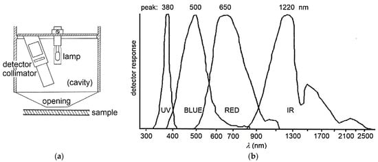
[13], was developed. This is a portable instrument which measures the radiation reflected by a test surface at an angle of 20° from the normal to the surface. A cavity in the measurement head (
Figure 2a) is painted with a highly reflecting material. Inside the head, a tungsten halogen lamp diffusely irradiates the cavity surface and, consequently, through an opening with a 2.5 cm diameter, the tested sample is placed against the head and closes that opening. Reflected light is measured with an assembly of four detectors. Each detector is equipped with color filters to concentrate its electrical response in a given wavelength range of the solar spectrum (
Figure 2b). Weighting properly the outputs of the four detectors, the response is obtained for incident solar radiation with the most commonly used spectral distributions and a desired air mass (from 0 to 2). By reciprocity relations among reflectances, the instrument yields the total hemispherical reflectance for beam radiation incident at a 20° angle from the normal to the surface. The instrument is calibrated with a black body cavity for zero-reflectance, and with reference samples of known radiative properties for higher reflectance values. A cross comparison with measurements performed according to ASTM E903 by means of a scanning spectrophotometer gave results in agreement within ±0.02 on a reflectance scale from 0 to 1
[16].
Figure 2. Solar spectrum reflectometer head (
a), sketch redrawn from
[17] and sensitivity curves of the embedded detectors (
b); patterns retraced from
[18].
Thanks to the ease of use and quickness of measurement by the solar reflectometer, modifications of the methods were also developed to measure the reflectance of variegated (in color) and/or textured surfaces, obtained by averaging a large number of randomly distributed reflectometer readings
[19][20][21]. These modifications are now incorporated in rating standards
[11][12].
Both the spectrophotometer and the solar spectrum reflectometer are well suited to test flat samples. Nonetheless, an approach was numerically developed
[22] and verified
[23] to correct measurements performed on flat samples and calculate the slight decrease of solar reflectance that takes place on different types of profiled roof surfaces such as high-profile tile, metal box rib, standing seam, etc., due to multiple reflection–absorption. An approach was also developed to test samples with a large-radius cylindrical surface
[24].
To the authors’ best knowledge, there is only one commercial instrument that complies with ASTM C1549
[25]. In its latest version (v6), two ‘virtual’ detectors were added to the four actual detectors centered on UV, Blue, Red and IR ranges, in order to better match the various solar irradiance spectra. The two virtual detectors are implemented by resampling the Red and IR detectors at a much lower color temperature of the lamp source
[26]. Moreover, rather than having fixed detector weightings, a custom set of weightings for each produced instrument is generated to best fit each solar irradiance spectrum, using a very large number of reference samples tested by different spectrophotometers
[26]. Nevertheless, to promote a fair comparison with products rated through previous versions of the instrument, the CRRC recommends using only the four given detectors for product rating, as well as the fixed weightings originally applied to match the beam normal air mass 1.5 spectrum from ASTM E891
[11][12]. As a matter of fact, this approach was found to slightly increase the solar reflectance readings and thus penalize samples tested with the more advanced instrument setup and weighting coefficients. The largest increases were observed for spectrally selective cool colors in tests performed with air mass 1 spectra
[23].
ASTM E903 and ASTM C1549 are equivalent test methods in the rating schemes of the CRRC
[11][12] and ECRC
[14], provided that the same spectrum from ASTM E891
[5] is used. The first method is best suited for laboratory use and research analyses, while the second one is targeted at in situ testing. However, solar spectrum reflectometers also seem to be largely used in the laboratory thanks to their speed of use and reasonable accuracy.
3. Pyranometer
A pyranometer measures the total radiant energy per unit time and unit surface area that falls onto the sensor surface. Spectrophotometers and reflectometers rely upon an embedded light source. Instead, the pyranometer-based technique specified in the ASTM E1918 standard test method
[27] relies upon actual solar radiation. The technique consists of taking readings from a pyranometer while it faces the sun, and immediately afterwards, while it faces the surface, in order to be characterized. The receiver of a pyranometer is a thermopile sensor coated with a black absorbent coating that absorbs the global (direct and diffuse), incident or reflected, solar radiation. The thermopile sensor, which is typically covered by a transparent dome, generates a voltage in response to the heat absorbed. ASTM E1918 recommends a double-dome design, with two thermopile-dome assemblies contemporarily facing upwards and downwards, in order to minimize the disturbing effects of convection inside the dome. Pyranometers and solar spectrum reflectometers were found to provide almost identical values of solar reflectance
[18], whereas a slightly looser agreement from 0.015 to 0.043 is reported between measurements according to ASTM E1918 and ASTM C1549 with air mass 1 global horizontal solar irradiance (AM1GH)
[23]. Using ASTM C1549 with the air mass 1.5 beam normal spectrum from ASTM E891 further increased the discrepancy.
The solar altitude must be high enough to get a good response in both the upwards and downward positions of the pyranometer. In this regard, ASTM E1918 recommends, for application on horizontal or low-slope roofs, a sun angle from the normal to the tested surface lower than 45°. As a result, there is a time window in which measurements can be performed, whose width depends on latitude and is larger in the summer, but shrinks and may become null in winter. The pyranometer sensor must be mounted at a height of 50 cm above the analyzed surface to minimize the effect of its shadow. The test area is a large circle at least 4 m in diameter, but it can be made as small as 1 m
2 with non-standard modifications of the method
[28][29]. The large test area however provides a unique advantage in that aggregates variegated in color and irregular or profiled surfaces can be easily tested in situ, obtaining their effective reflectance. In these cases, the CRRC accepts ASTM E1918 as a test method for product rating
[11][12]. However, the solar spectrum is relative to the place and time of the test and is not standard, therefore ASTM E903 or ASTM C1549 may be preferable in terms of fairness of product comparison whenever they can be used.
4. Non-Standard Test Methods for Advanced Solar-Reflective Materials
Directional reflective materials (DRMs) have been introduced to the roofing market. They can have a profiled surface that reflects solar radiation when the sun is high in the sky, and absorbs it when the sun is low, i.e., in winter
[30]. DRMs can also be designed to look dark from the street, e.g., to cope with color requirements, and light from the sky, toward which they reflect solar radiation. Applying standard test methods such as ASTM E903
[3], C1549
[13], or E1918
[23] to DRMs is impractical. Therefore, three choices of metric for product rating were proposed
[30], based on a mathematical model and the actual reflectances of the dark and light-colored surface areas: a single reflectance value during a year with a good performance in winter; a single reflectance value during a year with a good performance in summer; and different reflectance in the summer and winter (preferred choice).
In an urban canyon formed by buildings that face each other, sunlight entering the canyon is almost completely absorbed by the building surfaces due to multiple reflection–absorption effects—whichever is the reflectance of the façades. To mitigate the so-called urban canyon effect, retroreflective materials for façades are being investigated. One type can have a surface shape and finish that allows reflecting of the incident sunlight back to the sky. Retroreflective sheeting for traffic control has also been also tested
[31]. These sheets are made of glass bead lenses embedded in a transparent binder and applied onto a reflective substrate. It was shown that a retroreflective vertical surface with solar reflectance of 0.60 could return55% of incident sunlight to the sky, while a Lambertian (i.e., diffusely reflecting) surface with the same reflectance would reflect only 36% of sunlight skyward
[32]. Applying standard test methods to retroreflective materials is again impractical. Therefore, their reflectance was tested by comparing the sample temperatures under sunlight to those of non-retroreflective reference specimens
[33][34]. As an alternative, the angular distribution of spectral reflectance was assessed in the range of solar interest with a repositionable fiber-optic spectrophotometer
[35][36]. A two-axis solar gonio-spectrophotometer was also used, in which the specimen could be tilted from −90° to 90°, with three photodetectors covering the entire solar range
[37][38]. A repositionable photodetector with a broadband response over a significant part of the solar range and angles ranging from −70° to 70° was used to measure the angular distribution of light reflected from a sample illuminated with a normally incident xenon-arc artificial solar light source
[39]. As an alternative, a semicircular array of fixed photodiodes with broadband response was exploited, with angles ranging from −90° to 90°, and a xenon-arc artificial solar light source
[40], or a blue, green, or red laser source
[41].
Fluorescent materials such as quantum dots can re-emit light by photoluminescence. This provides an additional heat rejection mechanism in materials that rely on reflection alone; they show a potentially higher cooling capacity than conventional solar reflective materials with the same color
[42]. Their effective solar reflectance was calculated by comparing their temperatures in the sun to those of non-fluorescent reference specimens
[43].
5. Accessory Measurement of Thermal Emittance and Calculation of the Solar Reflectance Index (SRI)
In contrast to solar reflectance, on which this paper is focused, minimum values are seldom set for thermal emittance (also called infrared emittance, or emissivity). As already stated, this is the ratio of the energy that the considered surface emits toward the sky in the far infrared and the maximum theoretical emission at the same surface temperature. Like solar reflectance, it ranges from 0 to 1 (or 100%). A low thermal emittance can cause a surface to overheat even if it is highly reflective, because the fraction of solar energy that is absorbed, however small, cannot be efficiently returned to the celestial vault.
The thermal emittance is measured by several techniques. Narrowing the field to standard test methods that can be applied to built-up surfaces, an emissometer for laboratory or in situ measurement of the total hemispherical emittance can be based on ASTM C1371
[44]. The emissometer embeds a differential thermopile, which consists of a black-coated thermopile and another with a reflective coating. The emissometer head, in which both thermopiles are embedded, is warmed to provide the necessary temperature difference with respect to the tested sample. The differential thermopile signal is correlated to the heat flux exchanged by infrared radiation between the head and the sample surface after thermal equilibrium is achieved. The instrument is calibrated using two reference samples with high and low emittance. A widely used modification of the standard technique developed for thick samples with low thermal conductivity such as concrete, clay tiles, wood shingles, or insulation-backed membranes, is the ‘Slide method’
[45]. In this modification, the emissometer head is continuously moved over the sample to avoid warming it up. Both ASTM C1371 and the Slide method are included in the CRRC
[11][12] and ECRC
[14] rating programs. The ECRC also accepts another standard test method, specified in EN 15976
[46]. This was developed to measure the thermal emittance of low-emittance coatings for glazing; however, it can also be applied to opaque surfaces. It is conceptually analogous to ASTM C1371, with the difference that a thermal infrared (TIR) sensor of radiant heat flux is embedded in the emissometer head instead of the differential thermopile. Thanks to the quickness of response of such sensors, which do not require reaching of the thermal equilibrium of the head-sample system, the method can be used without modifications on thick samples made of non-conductive materials.
The thermal response of a surface due to the superposed effects of solar reflectance and thermal emittance is often given through the ‘solar reflectance index’ (SRI). This represents, in specified ambient conditions (air temperature, sky temperature, solar irradiance, wind velocity), the surface temperature decrease provided by the considered coating with respect to a reference black surface, divided by the surface temperature decrease provided by a reference highly reflective coating
[47][48]. SRI is evaluated in percentage terms through the relationship
[47]:
Ts (K) is the thermal equilibrium temperature of the tested surface while it is irradiated by a reference solar flux Isol as high as 1000 W/m2, the atmospheric air temperature Tair is 310 K, and the sky temperature Tsky is 300 K. Moreover, values of 5, 12, and 30 W/(m2K) are assigned to the convection heat transfer coefficient hc, respectively corresponding to low (<2 m/s), intermediate (between 2 and 6 m/s), and high (between 6 and 10 m/s) wind speed. Intermediate wind speed is the reference condition for product rating. Tb (K) and Tw (K) are the temperatures that are reached at thermal equilibrium by two reference surfaces: a black one with reflectance as low as 0.05 and the other white with reflectance as high as 0.80—both with high emissivity (ε = 0.90).
The surface temperature
Ts (as well as
Tb and
Tw) is calculated by iteratively solving the surface-heat balance at thermal equilibrium
[47]:
where
σ0 = 5.67·10
−8 W/(m
2K
4) is the Stefan–Boltzmann constant. This balance is based on the hypothesis of an adiabatic irradiated surface.
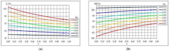
The calculation of SRI includes both solar reflectance and thermal emittance, as well wind conditions. Negative values or values higher than 100 can be obtained, as materials can exist with a poorer performance than the black reference surface, or superior to the white reference one. High values of solar reflectance and thermal emittance are contemporarily needed to keep the considered surface cool, unless the reflectance is very high (Figure 3). Generally speaking, it is worth mentioning that the emittance is usually around 0.9 for most built-up surfaces, being significantly lower only for metal surfaces with absent or very thin coating.
Figure 3. Surface temperature (a) and SRI (b) for reference ambient conditions and convection coefficient hc = 12 W/(m2K), as a result of intermediate wind speed (i.e., between 2 and 6 m/s); blue and red dots are for the reference white (ρsol,w = 0.80, εw = 0.90) and black (ρsol,b = 0.05, εb = 0.90) surfaces, respectively.
 +1 credit