 +1 credit
| Version | Summary | Created by | Modification | Content Size | Created at | Operation |
|---|---|---|---|---|---|---|
| 1 | Federica Buccino | + 2362 word(s) | 2362 | 2021-09-22 06:04:49 | | | |
| 2 | Nora Tang | + 870 word(s) | 3232 | 2021-09-23 08:53:51 | | | | |
| 3 | Lindsay Dong | Meta information modification | 3232 | 2021-10-09 11:40:13 | | |
Video Upload Options
The complexity of torsional load, its three-dimensional nature, its combination with other stresses, and its disruptive impact make torsional failure prevention an ambitious goal. However, even if the problem has been addressed for decades, a deep and organized treatment is still lacking in the actual research landscape. For this reason, this review aims at presenting a methodical approach to address torsional issues starting from a punctual problem definition. Accidents and breaks due to torsion, which often occur in different engineering fields such as mechanical, biomedical, and civil industry are considered and critically compared. More in depth, the limitations of common-designed torsion-resistant structures (i.e., high complexity and increased weight) are highlighted, and emerge as a crucial point for a deeper nature-driven analysis of novel solutions. In this context, an accurate screening of torsion-resistant bio-inspired unit cells is presented, taking inspiration specifically from plants, that are often subjected to the torsional effect of winds. As future insights, the actual state of technology suggests an innovative transposition to the industry: these unit cells could be prominently implied to develop novel metamaterials that could be able to address the torsional issue with a multi-scale and tailored arrangement.
1. Introduction: The Destructive Power of Torsional Load and the Extended Interest in It
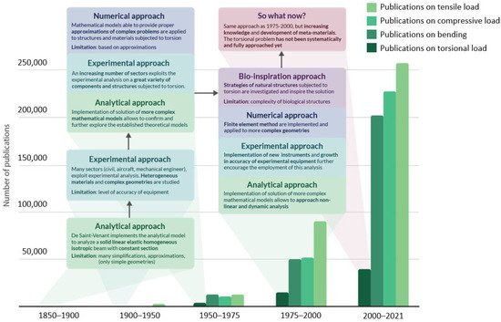
The evolution in approaching the torsional problem across years is presented in Figure 1 , which reports the occurrence of publications dedicated to torsional analysis and a comparison with works dedicated to other more commonly applied loads such as tension, compression, and bending. It is immediately evident that the research devoted to the torsional problem is drastically limited in comparison with the more common loads, specifically because of the already mentioned reasons.
An area of interest in which torsion is a matter of concern is civil engineering , where the aim is to better comprehend the behavior of buildings, bridges, or simply concrete beams under torsional static loads or dynamic loads, as in case of seismic events. In 1969, the theory of torsion in this sector has been described in more detail by Koll-Brunner and Basler [1], focusing on methods for the analysis of torsion of single-span or continuous members through the use of familiar tools for structural engineers. These solid, thin-walled, open or closed cross section structures are base elements for constructions, which even actually embrace torsion-related failures. For instance, as explained in the research of Kawashima et al. [2], piers of a skewed bridge could fail if subjected to extensive torsion damage (shown in Figure 2 A) as a consequence of an earthquake. The damage was a direct effect of seismic activity and it could be clearly recognized that the torsional fatigue failure crack had a 45° inclination.
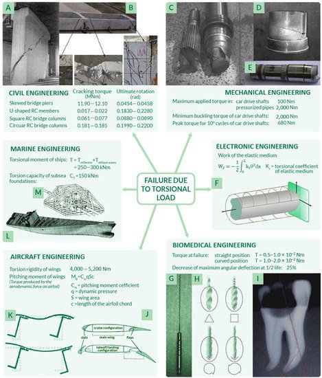
To be more precise, the load generated on bridge columns, foundations, walls, and in other civil structures is never steady and pure torsion, but usually a combination of different types of applied loads [3][4], characterized by a cyclic nature as analyzed by Kelly et al. [5]. Indeed, reinforced concrete beams, which undergo torsion failure, are a matter of concern even if strengthened with FRPs (fiber reinforced polymers), specifically designed for constructions. However, research on this topic is extremely limited [3], even though many authors have focused their research on beams under pure torsion condition, and specifically on both open section beams as in U-shaped thin-walled analyzed by Chen et al. [6] ( Figure 2 B), and closed section beams such as those described by Chariolis [7], Rao et al. [8], and Mondal et al. [3]. Again, in Figure 2 B, the typical inclination of 45° of torsional fatigue failure cracks could be observed. Note that the first attempts in investigating concrete beams under torsion loads go back to 1900 [9]: in the first fifty years of the twentieth century, many suggestions to determine a reliable analytical criterion and methodology for concrete beams subjected to combined stress due to bending and torsion were proposed [9][10]. As reported by Fisher [9], who performed both experimental tests on cylindrical reinforced concrete beams, a suitable failure criterion in these conditions could be maximum stress theory. As further reported by Kemp et al. in 1971 [10], the major issue related to reinforced concrete subjected to torsional load is that the applied loading condition is neither homogeneous nor isotropic. This leads to a lack of mathematical rigor and thus uncertainty in the design phase. Another possible reason for the lack of studies on torsion in civil structures relies on the fact that buildings are usually assumed to be composed of articulated simple vertical or horizontal elements specifically arranged so that torsion could be eliminated in the structural analysis. In case it could not be completely neglected, torsion is usually included in the safety factor choice in the design phase. Not only methods to prevent torsion failure, but torsion failure mechanisms have also been analyzed with the aim to better recognize and characterize them. Indeed, as previously anticipated, one of the main issues related to torsion analysis is that it is difficult to isolate, recognize, and observe, usually combined with other types of load (i.e., bending [9][11][12]). These usually have shell geometries, characterized by a far more complex analysis of stresses and strains if compared to beams [1]. To approach this complexity, many authors have suggested tailored torsion analysis methods, as in the case of Kumari et al. [13], who analyzed the behavior of a conoidal shell. Similarly, Zheleznov et al. [14] focused their attention on the issues of the stability of elliptical cylindrical shells subjected to torsion and internal pressure and solve them from the analytical point of view in the case of nonlinear deformation.
This difficulty must be added to another issue related to torsion analysis, concerning the fact that this type of load is rarely the primary cause of failure: it is often combined with bending [15] and it frequently does not directly cause failure, even though it contributes to it. One of the actual challenges is to determine the contribution of torsion and to associate its effects in terms of strains and deformations.
2. Common-Designed Torsion-Resistant Structures
According to the specific application, structures and features with specific torsion resistant features have been designed and are reported in Table 1 . Many of these structures have been commonly applied since the 1970s, as in the case of ship torsion boxes and torsional energy absorption devices, others have been introduced in the late nineties such as in the case of composite transmission power shafts. Some, such as the adaptive torsion wings, have only been conceptually modeled and lately investigated.
| Structure | Field of Interest | Schematic of the Structure | Potentialities | Limitations |
|---|---|---|---|---|
| Torsional energy absorbing devices [5] | Civil engineering | 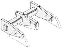 Adapted with permission from [5]. Copyright 1972 J. M. Kelly, R. I. Skinner, A. J. Heine |
|
|
| AR-Brace energy absorbing devices [16] | Civil engineering | 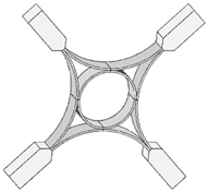 Adapted with permission from [16]. |
|
|
| Helicoidal steel reinforcements in concrete [10][17] | Civil engineering | 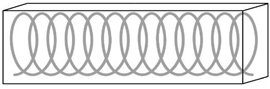 |
|
|
| Composite power shafts [19][20][21][18][22][23][24][25] | Mechanical engineering | 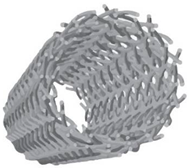 Adapted with permission from [20]. |
|
|
| Wings internal struts [26] | Aircraft engineering | 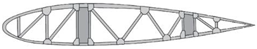 Adapted with permission from [26]. |
|
|
| Active aeroelastic structure devices [27] | Aircraft engineering | 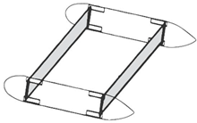 |
|
|
| Torsion boxes [28][29] | Marine engineering | 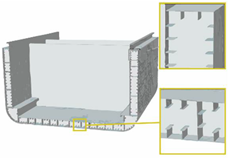 Adapted with permission from [29]. |
Lower stresses generated in the hull thanks to:
|
|
It can be observed that the common-designed torsion-resistant structures are characterized by some limitations. For instance, many of them are quite complex from the geometrical point of view: on one hand, this leads to the high complexity of numerical stress analysis and can affect the stress distribution, eventually causing local stress concentrations. On the other hand, the complexity of structures increases the costs of design and production of up to more than 250% if compared to conventional structures. The other main issue is weight increase, which could affect the performance of the components.
It is important to highlight the necessity to overcome these evident limitations through a transversal approach, considering the impressive power of nature-designed solutions [28].
3. Overcoming the Limitations of Traditional Structures from a Natural Perspective
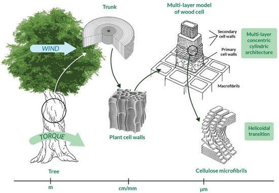
Innovative solutions to face the torsional issue have recently been searched in nature, interrogated as a source of inspiration [28][30]. Many natural structures are subjected to torsional loads; some examples are tree trunks and wood cells and every bird and insect wing. Nature deals with torsion since the first birth species and the result is that there exist many systems in nature that develop torsion resistance through specific mechanisms and/or structural arrangements. For this reason, researchers consider nature as a qualified source of inspiration to develop torsion-resistant structures. Indeed, biomimicry and bio-inspiration are sciences based exactly on this concept [31], according to which scientists should respectively mime nature or let their research be inspired by it, lowering as much as possible the impact on the Earth and obtaining more sophisticated technologies, processes, and ecosystems [32][33]. Biological materials are able to optimally perform under different loads due to their complex and hierarchical structures, which go from macroscale to microscale [34]. Indeed, biological structures vary at different levels [35] and the interaction between them could provide specific torsional properties to the system as a whole. As an example, the complex hierarchical structure of wood is illustrated in Figure 3 and is characterized by more than five levels of hierarchy, as described in International Standard ISO 18457 (2016) on biomimetics [36][37]. Note that the multi-layer concentric cylindric structure of wood cells provide torsion resistance [38] and that the helicoidal transitions at the microscale avoid discontinuities in the change of properties between different levels of the entire structure [39].
To develop torsional bioinspired structures, the problem analysis should be performed first (i.e., the description of the problem related to torsion resistance). Examples of problem analysis are reported in Section 1.1 , together with a detailed collection of components and structures commonly subjected to torsional damage or failure. There are many fields of interest in which the development of an optimal torsion resistant structure might lead to an improvement in conventionally designed engineering components. For this reason, potentially prominent biological models were analyzed and critically compared.
A different example of a natural torsion-resistant unit cell in which helices are present is Bouligand’s structure [40] ( Table 2 , fourth unit cell), largely diffused in most arthropod cuticle. Indeed, the arthropod epidermal cells are characterized by a periodic architecture, with a helicoidal stacking of unidirectional chitin–protein fibrils set in an amorphous matrix [39][41]. The name of this structure comes from Bouligand, who dedicated his studies on the description of this twisted fibrous arrangement, which has then been largely observed in biological materials and tested under torsion [40]. Typically, Bouligand’s model could be recognized by a characteristic parabolic pattern that can be geometrically interpreted as an oblique section visualization of the layered and twisted structure resembling plywood [42], where consecutive layers of fibrils have a constant angle of twisting.
| Bio-Inspired Structure | Biological Organism | Unit Cell Structure | Torsion Resistant Features | Performed Tests |
|---|---|---|---|---|
| Helicoidal laminae in solid or hollow cylinders [22][43][44][45][46][47] | Tusk of narwhal, hippopotamus, African and Indian elephant, sperm and killer whale, boar, walrus | 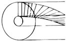 Adapted with permission from [43] |
Fibers tangential to cylinder’s axis are helicoidally arranged. | Helix-reinforced composite, ZrO2 and epoxy (60:40), 45°:
|
| Multi-layer concentric cylindric architecture [37][38][48][49][50][51] | Wood cells, bone osteons, insect cuticle and skeleton of glass sponges | 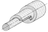 Adapted with permission from [52] |
Cylindric layers can have:
|
0Wood cell-wall with cellulose microfibril angle of 50° → fracture strain: 13.5%; Bone osteons → compressive modulus of lamellae: 20 GPa Wood-inspired composite → compressive modulus variation for a winding angle of 45°: +150% |
| Helically reinforced cylinder [52][26][39][53][54][55][56][57][58] | Root cortex cells of most Asplenium species, herbaceous plants (sunflower), tree stem | 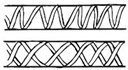 |
Fibers arranged according to single or double helices on a cylindrical surface. | Tree stem (14 cm of diameter) → breaking load in torsion test: 275 MPa |
| Twisted plywood (Bouligand’s structure) [39][40][41][42][51][59][60][61][62][63][64][65] | Arthropod cuticle (crab, lobster, mantis shrimp, arachnids and myriapods), | 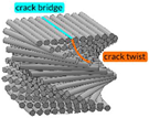 Adapted with permission from [65] |
Layered and twisted structure in which consecutive layers of parallel fibers have a constant angle of twisting. | Bouligand composite structure, RGD720 and polyester (22:78) → Peak torque: 7.5 Nm, Rotation: 2.0 ± 5.3 × 10⁻² rad Impact forces repetitively endured: ≤1500 N |
Bouligand’s structure has been proven to have a remarkable fracture toughness [62], well beyond its constituents, thanks to a combination of two main propagation modes controlled by that arrangement of chitin–protein: crack twisting and bridging ( Table 2 ). Indeed, before the fracture begins, the twisted plywood allows reorientation and deformation of fibers in response to torsional loadings [66]. In other words, Bouligand’s structure ductility and toughness are biologically designed to prevent fracture through changes in the structural arrangement. Furthermore, Bouligand’s structure has exceptional stiffness and hardness [65][67][68] and, similar to that discussed for ivory, optimized bending and torsion resistance can be inspired by this structure, as proven by works such as the one by Nikolov et al. on high-performance composite structures [63]. To provide an idea of the wide diffusion of this architecture in nature, it is worth mentioning that arthropods are a kind of invertebrate animal that covers more than half the classified species [60], proving that their biological structures, and specifically their torsion-resistant properties, are highly performing and adaptable [40][41][61][62][63][64][65][69][70][71]. Arthropods include insects, arachnids, myriapods, and crustaceans that have a cuticle with a twisted plywood. Furthermore, Bouligand’s structure can be associated with micro- and nanoscale architecture (i.e., cholesteric liquid crystal), which, as explained by Mitov [72], are omnipresent in nature: chitin, cellulose, collagen, and silk are characterized by the Bouligand arrangement [39].
4. From Nature to Novel Materials: Torsion-Resistant Metamaterials
Eventually, nature-inspired structures have been exploited in the design of novel metamaterials that are able to actively address the torsion-resistance issue with innovative and customized solutions. Following the problem-driven approach defined in Section 3.2 , phase 2 is now faced and the biological strategies abstracted from natural torsion-resistant unit cells are transposed to technology and tested.
Metamaterials are characterized by properties not simply given by their composition, but arising from their structure [73]; they are usually assembled starting from one or more basic unit elements that repeat themselves, forming a clinical pattern [74]. An example is the metamaterial conceived by Zhong et al. [75], which was able to convert axial compression (or tension) into torsion: the unit cell, the following metamaterial, and the final tested specimen are illustrated in Figure 5 A. Note that the unit cell of this material is characterized by an arrangement of rods, which resembles the helical structures described in Section 3.3 . The proposed design allows for a promising peak value of 16.2° of torsion angle to be reached. Possible applications of this metamaterial are wave converters, able to transform shear waves into longitudinal waves and vice versa, or morphing structures in aircraft and aerospace engineering [75].
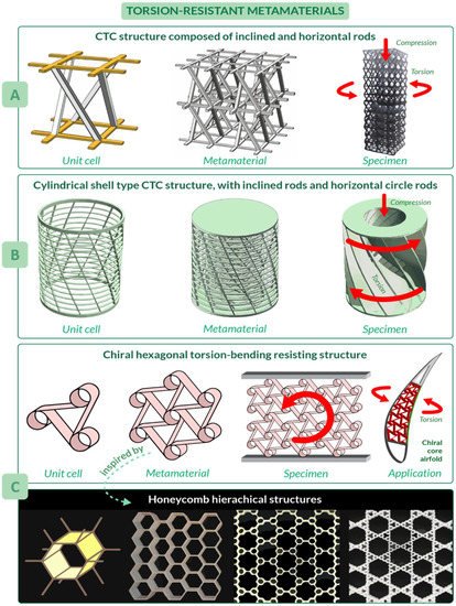
Another compression-torsion-conversion (CTC) metamaterial has been proposed by Wang et al. [76], which focused their attention not only on the properties of the final structure, but also on the main problem of metamaterials such as inefficient use of space. Their work introduces a cylindrical metamaterial, increasing the capability of compression and torsion resistance [76]. Its unit cell has inclined and horizontal circle rods, which resembles the helical and annular features of natural unit cells, respectively ( Figure 5 B). The most crucial benefit of this structure is the tailored torsion resistance coming from the relationship between rod inclination angle and the torsion angle of the rotation spring: the larger the rod inclination angle and slenderness ratio, the larger the torsion angle. The metamaterial consists of three of the cylindrical shells, differing in radius, arranged one inside the other. Since manufacturing of these structures, also known as rotation springs, is quite problematic, a continuous structure with curved surfaces has been proposed for tests. Applications of these metamaterials include structures of machinery and vehicles.
Considering the need to design lightweight components, promising metamaterials have been inspired by honeycombs. As shown by Haghpanah et al. [77], from the basic concept of hexagonal honeycomb, more complex hierarchical structures with an improved efficiency could be developed, as in the case of self-similar hierarchical honeycombs shown in Figure 5 C. An example of structure inspired by honeycombs is the morphing airfoil designed by Bettini et al. [78][79], where a composite chiral element, which resembles honeycomb hexagons and spirals (largely diffused in nature [80][81][82][83]), was used in the core of the airfoil to resist torsion and bending during flight. To be more precise, this metamaterial can improve morphing performances by increasing the maximum allowable displacement, which can reach in tension up to 12% of cell dimension and about 30% in compression.
References
- Kollbrunner, C.F.; Basler, K. Torsion in Structures; Springer: Berlin/Heidelberg, Germany, 1969.
- Tirasit, P.; Kawashima, K. Effect of nonlinear seismic torsion on the performance of skewed bridge piers. J. Earthq. Eng. 2008, 12, 980–998.
- Rakoczy, A.M.; Asce, A.M.; Otter, D.E.; Asce, M.; Malone, J.J.; Farritor, S. Railroad Bridge Condition Evaluation Using Onboard Systems Introduction and Motivation. 2016. Available online: https://ascelibrary.org/doi/abs/10.1061/%28ASCE%29BE.1943-5592.0000881 (accessed on 16 July 2021).
- Prakash, S.; Belarbi, A.; You, Y.M. Seismic performance of circular RC columns subjected to axial force, bending, and torsion with low and moderate shear. Eng. Struct. 2010, 32, 46–59.
- Kelly, J.M.; Skinner, R.I.; Heine, A.J. Mechanisms of Energy Absorption in Special Devices for Use in Earthquake Resistant Structures. Bull. N. Z. Soc. Earthq. Eng. 1972, 5, 63–73.
- Chen, S.; Diao, B.; Guo, Q.; Cheng, S.; Ye, Y. Experiments and calculation of U-shaped thin-walled RC members under pure torsion. Eng. Struct. 2016, 106, 1–14.
- Chalioris, C.E. Analytical model for the torsional behaviour of reinforced concrete beams retrofitted with FRP materials. Eng. Struct. 2007, 29, 3263–3276.
- Rao, T.D.G.; Rama Seshu, D. Analytical model for the torsional response of steel fiber reinforced concrete members under pure torsion. Cem. Concr. Compos. 2005, 27, 493–501.
- Fisher, D. The strenght of concrete in combined bending torsion. Univ. Lond. 1950, 61, 1509–1522.
- Kemp, E.L.; Sozen, M.A.; Siess, C.P. Torsion in Reinforced Concrete. 1961. Available online: https://www.ideals.illinois.edu/handle/2142/13762 (accessed on 16 July 2021).
- Lampert, P.; Thürlimann, B. Ultimate Strength and Design of Reinforced Concrete Beams in Torsion and Bending. In Ultimate Strength and Design of Reinforced Concrete Beams in Torsion and Bending/Résistance et dimensionnement des poutres en béton armé soumises à la torsion et à la flexion/Bruchwiderstand und Bemessung von Stahlbetonbalken unter Torsion und Biegung; Birkhäuser: Basel, Switzerland, 1972; Volume 42, pp. 107–131.
- Elfren, L.; Karlsson, I.; Losberg, A. Torsion-Bending-Shear-Interaction for Concrete Beams. ASCE J. Struct. Div. 1974, 100, 1657–1676.
- Kumari, S.; Chakravorty, D. On the bending characteristics of damaged composite conoidal shells—A finite element approach. J. Reinf. Plast. Compos. 2010, 29, 3287–3296.
- Zheleznov, L.P.; Kabanov, V.V.; Boiko, D.V. Nonlinear Deformation and Stability of Discrete-Reinforced Elliptical Cylindrical Composite Shells under Torsion and Internal Pressure. Russ. Aeronaut. 2018, 61, 175–182.
- Wolff-Vorbeck, S.; Langer, M.; Speck, O.; Speck, T.; Dondl, P. Twist-to-bend ratio: An important selective factor for many rod-shaped biological structures. Sci. Rep. 2019, 9, 17182.
- Ismail, M. New approach to seismic-resistant design and structural torsion mitigation. Eng. Struct. 2020, 207, 110092.
- Hadi, M.N.S.; Schmidt, L.C. Use of helixes in reinforced concrete beams. ACI Struct. J. 2018, 115, 191–198.
- Hao, W.; Huang, Z.; Zhang, L.; Zhao, G.; Luo, Y. Study on the torsion behavior of 3-D braided composite shafts. Compos. Struct. 2019, 229, 111384.
- Leelavathi, A.V.R. Design & Analysis of an Automotive Composite Drive Shaft. Int. J. Res. Eng. Sci. 2020, 8, 24–28.
- Hao, W.; Liu, Y.; Huang, X.; Liu, Y.; Zhu, J. A unit-cell model for predicting the elastic constants of 3d four directional cylindrical braided composite shafts. Appl. Compos. Mater. 2017, 25, 619–633.
- Shokrieh, M.M.; Hasani, A.; Lessard, L.B. Shear buckling of a composite drive shaft under torsion. Compos. Struct. 2004, 64, 63–69.
- Porter, M.M.; Meraz, L.; Calderon, A.; Choi, H.; Chouhan, A.; Wang, L.; Meyers, M.A.; McKittrick, J. Torsional properties of helix-reinforced composites fabricated by magnetic freeze casting. Compos. Struct. 2015, 119, 174–184.
- Lee, D.G.; Kim, H.S.; Kim, J.W.; Kim, J.K. Design and manufacture of an automotive hybrid aluminum/composite drive shaft. Compos. Struct. 2004, 63, 87–99.
- Mutasher, S.A. Prediction of the torsional strength of the hybrid aluminum/composite drive shaft. Mater. Des. 2009, 30, 215–220.
- Yu, G.; Gao, X.; Song, Y. Experimental investigation of the tension-torsion coupling behavior on needled unidirectional C/SiC composites. Mater. Sci. Eng. A 2017, 696, 190–197.
- Sullivan, T.N.; Wang, B.; Espinosa, H.D.; Meyers, M.A. Extreme lightweight structures: Avian feathers and bones. Mater. Today 2017, 20, 377–391.
- Ajaj, R.M.; Friswell, M.I.; Dettmer, W.G.; Allegri, G.; Isikveren, A.T. Conceptual modeling of an adaptive torsion wing structure. In Proceedings of the 52nd AIAA/ASME/ASCE/AHS/ASC Structures, Structural Dynamics and Materials Conference, Denver, CO, USA, 4–7 April 2011.
- Shama, M. Torsion and shear stresses in ships. Torsion Shear Stress. Ships 2010, 1, 1–277.
- Alfred Mohammed, E.; Benson, S.D.; Hirdaris, S.E.; Dow, R.S. Design safety margin of a 10,000 TEU container ship through ultimate hull girder load combination analysis. Mar. Struct. 2016, 46, 78–101.
- Libonati, F.; Gu, G.X.; Qin, Z.; Vergani, L.; Buehler, M.J. Bone-Inspired Materials by Design: Toughness Amplification Observed Using 3D Printing and Testing. Adv. Eng. Mater. 2016, 18, 1354–1363.
- Katiyar, N.K.; Goel, G.; Hawi, S.; Goel, S. Nature-inspired materials: Emerging trends and prospects. NPG Asia Mater. 2021, 13, 1–16.
- du Plessis, A.; Broeckhoven, C.; Yadroitsava, I.; Yadroitsev, I.; Hands, C.H.; Kunju, R.; Bhate, D. Beautiful and Functional: A Review of Biomimetic Design in Additive Manufacturing. Addit. Manuf. 2019, 27, 408–427.
- Pathak, S. Biomimicry: Innovation Inspired by Nature; William Morrow & Co.: London, UK, 2019; Volume 5.
- Meyers, M.A.; Chen, P.Y.; Lin, A.Y.M.; Seki, Y. Biological materials: Structure and mechanical properties. Prog. Mater. Sci. 2008, 53, 1–206.
- Munch, E.; Launey, M.E.; Alsem, D.H.; Saiz, E.; Tomsia, A.P.; Ritchie, R.O. Tough, bio-inspired hybrid materials. Science 2008, 322, 1516–1520.
- Fayemi, P.E.; Wanieck, K.; Zollfrank, C.; Maranzana, N.; Aoussat, A. Biomimetics: Process, tools and practice. Bioinspir. Biomim. 2017, 12, 011002.
- BS ISO 18457:2016 BSI Standards Publication Biomimetics—Biomimetic Materials, Structures and Components. 2016. Available online: https://www.iso.org/standard/62499.html (accessed on 9 July 2021).
- Zorzetto, L.; Ruffoni, D. Wood-Inspired 3D-Printed Helical Composites with Tunable and Enhanced Mechanical Performance. Adv. Funct. Mater. 2019, 29, 1805888.
- Neville, A.C. Biology of Fibrous Composites; Cambridge University Press: Cambridge, UK, 1993.
- Bouligand, Y. Twisted fibrous arrangements in biological materials and cholesteric mesophases. Tissue Cell 1972, 4, 189–217.
- Raabe, D.; Sachs, C.; Romano, P. The crustacean exoskeleton as an example of a structurally and mechanically graded biological nanocomposite material. Acta Mater. 2005, 53, 4281–4292.
- Neville, A.C.; Thomas, M.G.; Zelazny, B. Pore canal shape related to molecular architecture of arthropod cuticle. Tissue Cell 1969, 1, 183–200.
- Locke, M. Structure of ivory. J. Morphol. 2008, 269, 423–450.
- Kingsley, M.C.S.; Ramsay, M.A. The Spiral in the Tusk of the Narwhal. Arctic 1988, 41, 236–238.
- Currey, J.D.; Brear, K.; Zioupos, P. Dependence of mechanical properties on fibre angle in narwhal tusk, a highly oriented biological composite. J. Biomech. 1994, 27, 885–897.
- Zioupos, P.; Currey, J.D. Pre-failure toughening mechanisms in the dentine of the narwhal tusk: Microscopic examination of stress/strain induced microcracking. J. Mater. Sci. Lett. 1996, 15, 991–994.
- Jopek, H.; Strek, T. Torsion of a Two-Phased Composite Bar with Helical Distribution of Constituents. Phys. Status Solidi Basic Res. 2017, 254–266.
- Fratzl, P.; Weinkamer, R. Nature’s hierarchical materials. Prog. Mater. Sci. 2007, 52, 1263–1334.
- Emons, A.M.C.; Mulder, B.M. The making of the architecture of the plant cell wall: How cells exploit geometry. Proc. Natl. Acad. Sci. USA 1998, 95, 7215–7219.
- Roland, J.C.; Mosiniak, M. On the twlstlng pattern, texture and layering of the secondary cell walls of lime wood. Proposal of an unifying model. IAWA J. 1983, 4, 15–26.
- Lichtenegger, H.; Müller, M.; Paris, O.; Riekel, C.; Fratzl, P. Imaging of the helical arrangement of cellulose fibrils in wood by synchrotron X-ray microdiffraction. J. Appl. Crystallogr. 1999, 32, 1127–1133.
- Kubler, H. Function of Spiral Grain in Trees; Springer: Berlin/Heidelberg, Germany, 1991; Volume 5.
- Skatter, S.; Kučera, B. Spiral grain—An adaptation of trees to withstand stem breakage caused by wind-induced torsion. Holz als Roh-und Werkst. 1997, 55, 207–213.
- Thunell, B. Uber die Drehwiichsigkeif. Holz als Roh-und Werkst 1951, 9, 293–297.
- Leroux, O.; Bagniewska-Zadworna, A.; Rambe, S.K.; Knox, J.P.; Marcus, S.E.; Bellefroid, E.; Stubbe, D.; Chabbert, B.; Habrant, A.; Claeys, M.; et al. Non-lignified helical cell wall thickenings in root cortical cells of Aspleniaceae (Polypodiales): Histology and taxonomical significance. Ann. Bot. 2011, 107, 195–207.
- Vogel, S. Comparative Biomechanics: Life’s Physical World; Princeton Univ Press: Woodstock, UK, 2013.
- De Margerie, E.; Sanchez, S.; Cubo, J.; Castanet, J. Torsional resistance as a principal component of the structural design of long bones: Comparative multivariate evidence in birds. Anat. Rec.-Part A Discov. Mol. Cell. Evol. Biol. 2005, 282, 49–66.
- Niklas, K.J.; Spatz, H.C.; Vincent, J. Plant biomechanics: An overview and prospectus. Am. J. Bot. 2006, 93, 1369–1378.
- Giraud, M.M.; Castanet, J.; Meunier, F.J.; Bouligand, Y. The fibrous structure of coelacanth scales: A twisted “Plywood”. Tissue Cell 1978, 10, 671–686.
- Edgecombe, G.D. Arthropod phylogeny: An overview from the perspectives of morphology, molecular data and the fossil record. Arthropod Struct. Dev. 2010, 39, 74–87.
- Chen, P.Y.; Lin, A.Y.M.; Lin, Y.S.; Seki, Y.; Stokes, A.G.; Peyras, J.; Olevsky, E.A.; Meyers, M.A.; McKittrick, J. Structure and mechanical properties of selected biological materials. J. Mech. Behav. Biomed. Mater. 2008, 1, 208–226.
- Wu, K.; Song, Z.; Zhang, S.; Ni, Y.; Cai, S.; Gong, X.; He, L.; Yu, S.H. Discontinuous fibrous Bouligand architecture enabling formidable fracture resistance with crack orientation insensitivity. Proc. Natl. Acad. Sci. USA 2020, 117, 15465–15472.
- Nikolov, S.; Petrov, M.; Lymperakis, L.; Friák, M.; Sachs, C.; Fabritius, H.O.; Raabe, D.; Neugebauer, J. Revealing the design principles of high-performance biological composites using Ab initio and multiscale simulations: The example of lobster cuticle. Adv. Mater. 2010, 22, 519–526.
- Hassan, S.A.; Santulli, C.; Yahya, M.Y.B.; Gang, C.L.; Abu Bakar, M.N.F.B. The potential of biomimetics design in the development of impact resistant material. FME Trans. 2018, 46, 108–116.
- Suksangpanya, N.; Yaraghi, N.A.; Kisailus, D.; Zavattieri, P. Twisting cracks in Bouligand structures. J. Mech. Behav. Biomed. Mater. 2017, 76, 38–57.
- Zimmermann, E.A.; Gludovatz, B.; Schaible, E.; Dave, N.K.N.; Yang, W.; Meyers, M.A.; Ritchie, R.O. Mechanical adaptability of the Bouligand-type structure in natural dermal armour. Nat. Commun. 2013, 4, 2634.
- Studart, A.R. Towards high-performance bioinspired composites. Adv. Mater. 2012, 24, 5024–5044.
- Suksangpanya, N.; Yaraghi, N.A.; Pipes, R.B.; Kisailus, D.; Zavattieri, P. Crack twisting and toughening strategies in Bouligand architectures. Int. J. Solids Struct. 2018, 150, 83–106.
- Pimentel, D.; Wheeler, A.G. Species and Diversity of Arthropods in the Alfalfa Community. Environ. Entomol. 1973, 2, 659–668.
- Akam, M. Arthropods: Developmental diversity within a (super) phylum. Proc. Natl. Acad. Sci. USA 2000, 97, 4438–4441.
- Chen, P.Y.; Lin, A.Y.M.; McKittrick, J.; Meyers, M.A. Structure and mechanical properties of crab exoskeletons. Acta Biomater. 2008, 4, 587–596.
- Mitov, M. Cholesteric liquid crystals in living matter. Soft Matter 2017, 13, 4176–4209.
- Sihvola, A. Metamaterials: A Personal View. Radioengineering 2009, 18, 90–94.
- Libonati, F.; Vellwock, A.E.; El Louizi, F.; Hoffmann, R.; Colombo, C.; Ziegmann, G.; Vergani, L. Squeeze-winding: A new manufacturing route for biomimetic fiber-reinforced structures. Compos. Part A Appl. Sci. Manuf. 2020, 132, 105839.
- Zhong, R.; Fu, M.; Chen, X.; Zheng, B.; Hu, L. A novel three-dimensional mechanical metamaterial with compression-torsion properties. Compos. Struct. 2019, 13, 36416–36425.
- Wang, Y.B.; Liu, H.T.; Zhang, Z.Y. Rotation spring: Rotation symmetric compression-torsion conversion structure with high space utilization. Compos. Struct. 2020, 245, 112341.
- Haghpanah, B.; Oftadeh, R.; Papadopoulos, J.; Vaziri, A. Self-similar hierarchical honeycombs. Proc. R. Soc. A Math. Phys. Eng. Sci. 2013, 469, 2163–2175.
- Bettini, P.; Airoldi, A.; Sala, G.; Landro, L.D.; Ruzzene, M.; Spadoni, A. Composite chiral structures for morphing airfoils: Numerical analyses and development of a manufacturing process. Compos. Part B Eng. 2010, 41, 133–147.
- Airoldi, A.; Bettini, P.; Zazzarini, M.; Scarpa, F. Failure and energy absorption of plastic and composite chiral honeycombs. WIT Trans. Built Environ. 2012, 126, 101–114.
- Harrison, L.G. On growth and form. Nature 1995, 375, 745–746.
- Wada, K. Spiral growth of nacre. Nature 1966, 211, 1427.
- Harary, G.; Tal, A. The natural 3D spiral. Comput. Graph. Forum 2011, 30, 237–246.
- Hollis, W.A. The curve of life. Nature 1899, 59, 224.

