Your browser does not fully support modern features. Please upgrade for a smoother experience.
Submitted Successfully!
 +1 credit
Thank you for your contribution! You can also upload a video entry or images related to this topic.
For video creation, please contact our Academic Video Service.
| Version | Summary | Created by | Modification | Content Size | Created at | Operation |
|---|---|---|---|---|---|---|
| 1 | Amir Mosavi | + 6873 word(s) | 6873 | 2021-08-11 04:53:08 | | | |
| 2 | Bruce Ren | -21 word(s) | 6852 | 2021-08-19 09:48:02 | | |
Video Upload Options
We provide professional Academic Video Service to translate complex research into visually appealing presentations. Would you like to try it?
Cite
If you have any further questions, please contact Encyclopedia Editorial Office.
Mosavi, A. Composite Electromagnetic Shielding Applications. Encyclopedia. Available online: https://encyclopedia.pub/entry/13350 (accessed on 13 June 2026).
Mosavi A. Composite Electromagnetic Shielding Applications. Encyclopedia. Available at: https://encyclopedia.pub/entry/13350. Accessed June 13, 2026.
Mosavi, Amir. "Composite Electromagnetic Shielding Applications" Encyclopedia, https://encyclopedia.pub/entry/13350 (accessed June 13, 2026).
Mosavi, A. (2021, August 19). Composite Electromagnetic Shielding Applications. In Encyclopedia. https://encyclopedia.pub/entry/13350
Mosavi, Amir. "Composite Electromagnetic Shielding Applications." Encyclopedia. Web. 19 August, 2021.
Copy Citation
With advancements in the automated industry, electromagnetic inferences (EMI) have been increasing over time, causing major distress among the end-users and affecting electronic appliances. The issue is not new and major work has been done, but unfortunately, the issue has not been fully eliminated.
electromagnetic inference
shielding effectiveness
graphene
iron
polymer
composite materials
materials
review
materials design
computational materials design
1. Introduction
Electromagnetic interference (EMI) has emerged as a global issue due to the rapid growth of electronic devices and their usage in day-to-day life [1]. Electromagnetic pollution is triggering loss of data, signal disturbing, system failures and most importantly causing a serious threat to information communication security and human health [2][3][4]. Owing to the increased usage of these electromagnetic devices, radiation of the electromagnetic (EM) wave has become a serious concern because these radiations not only become disastrous for electronic equipment but also affecting human health [5]. With the advancement in technologies, human exposure to electromagnetic fields is getting common and unavoidable [6][7][8]. Electromagnetic waves do not deflect by any magnetic or electric field and cause serious issues [9]. Electromagnetic waves are causing damages in various forms such as changes in physiological indices, genetic effects, health, and immune functions. With time, the adverse effects are getting higher which requires vital attention [10][11]. The penetration of the EM waves in the shielding materials is a critical aspect at higher frequencies [12]. Electromagnetic waves are non-mechanical which travel at the speed of light. They can be produced by accelerated charge and do not involve any medium for transmission [9]. Electromagnetic waves are also known as electromagnetic radiation as they radiate from charged electrical particles. The transmission could be through air, space, or any other substance. Low frequency electromagnetic waves are stated as electromagnetic fields, whereas high frequency electromagnetic waves are known as electromagnetic radiations [13][14]. EMI shielding has been in consideration since World War II to reduce the impact of electromagnetic waves on electronic appliances [15]. As per Scopus [16] database, Figure 1 portrays the number of experimental studies conducted on EMI shielding to date.
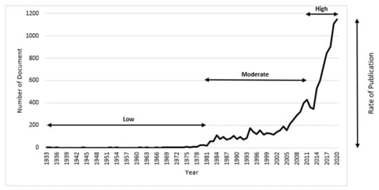
Figure 1. Studies conducted on EMI shielding.
From Figure 1, it can be observed that work started on electromagnetic shielding in 1933. The studies conducted on electromagnetic shielding were fewer from 1933 to 1981 and started to rise later. The peak was observed in 2020 with 1146 publications. Over time, a gradual increase can also be observed, which indicates the importance of this issue. Many researchers have introduced various materials to overcome the EMI effect by providing better electromagnetic shielding effectiveness. Some pre-existing materials with hidden shielding properties were identified, and some were made in labs and later were implemented for industrial usage. The most common materials used as electromagnetic shielding are metals, carbon, iron, graphene and polymers, etc. Various EMI shielding materials have been developed and implemented in industry to tackle electromagnetic inference. Researchers have adopted different strategies to deal with the EMI issue where some used material coatings and some developed new composites. The preferences of selection of materials have changed as their properties have been explored more in-depth. In the mid-1900s different materials were introduced as EMI shielding materials. Nickel-based composites were famous as coatings to enhance EMI shielding. Besides that, copper, silver and graphite coatings were also utilized as they form a good barrier to protect devices from ambient electromagnetic interference [17]. Macfarlane et al. [18] conducted a study, where an yttrium barium cuprate superconductor was used as an electromagnetic shielding material. However, it is universal that all the superconductive composites give better EMI shielding. YBa2Cu3O7−x superconductive material was used for EMI shielding, where it was revealed that the composite does not provide effectiveness against electromagnetic waves [19]. Carbon fibre was also used as EMI shielding, where it was reported that with an increase in the fibre content, the conductivity increases, which enhances the EMI shielding effectiveness [20][21].
Metals have received attention as EMI shielding materials when used individually and in combination with other materials by forming alloy composites. Moreover, metal fillers were also used for enhancing EMI shielding effectiveness [22][23][24][25][26]. The most used materials are metal sheets and metal foam. Metal sheets include brass, silver, copper, nickel, tin, and steel. The effectiveness of electromagnetic shielding gets affected by the metal’s physical properties such as thickness, weight, permeability, conductivity and solderability, which change the reflection and absorption capabilities. Metals’ properties play an important role in the material section as EMI shielding. High conductive metals (brass, copper, silver) reflects electrically dominant waves, whereas, less conductive metal (steel) absorb magnetically dominant waves [27][28]. Metal foam got hype due to its use in both scientific and industrial applications. Metal foams are composite structures comprised of metal (aluminium) and gas (mainly air is added). The combination of these two results in a disordered wire mesh having low density [29][30][31][32][33]. Authors earlier gave a brief state of the art review on graphene and iron reinforced polymer composites for electromagnetic shielding applications [28]. However, still there is a gap for an in-dept understanding and comprehensive review. Carbon materials and their composites gained attention in the field of EMI shielding because of their better conductivity and flexibility [34][35][36]. Carbon fillers such as carbon black and carbon fibre were also used to achieve EMI shielding effectiveness. Later on, carbon particles and carbon nanotubes were introduced which showed good results [37]. However, a few studies have suggested that carbon-based materials have limited mechanical flexibility, where metal-based materials suffer from corrosion and are heavy in weight, due to which it becomes difficult to achieve high shielding effectiveness [38]. Therefore, there is a great need for developing a shielding material that is light and durable, at low cost, produces no pollution, have comprehensive performance and shielding frequency bandwidth [39]. Thus, the microstructure of the nanomaterials, the structure of the shield and the inclusion of foreign materials such as materials with dielectric or magnetic dipoles play an important role in the absorption of the EM waves [12].
Conducting polymer composites earned recognition in comparison to metal-based composites due to their flexibility, lightweight and resistance to corrosion [40][41][42][43]. Various researchers utilized polymer-based materials as they are lightweight in comparison to metal-based materials. However, polymer-based materials give less shielding against EMI as they are less conductive and have been used in combination with other materials which comes as a good absorber for electromagnetic waves [44][45][46][47][48]. The polymer-based materials have been identified as the ideal materials for EMI shielding effectiveness [49][50]. With the introduction of the 5th Generation (5G) telecommunication system and high frequency range electronic interfaces, the EM pollution has been increased drastically, hence, the coupling effect of EM radiation and signals interferences requires suppressed [51][52]. Therefore, this study aims to review the past studies conducted to deal with the electromagnetic inferences through graphene, iron and polymer composites. The focus of this review is mainly limited to the combination of the Graphene@Iron@Polymer family as an EMI shielding material within the range of X-band frequency and above.
2. Graphene-Based Composites
Graphene is a 2D planar sheet and is an allotrope of carbon that is organized into a hexagonal lattice as shown in Figure 1. A single graphene sheet has a honeycomb structure, which forms due to the arrangement of a single layer of carbon atoms. When several sheets pile on each other, they form multi-layer graphene. The structure of graphene is such that each carbon atom is attached to the other three carbon atoms which provide better stability and high tensile strength [53][54].
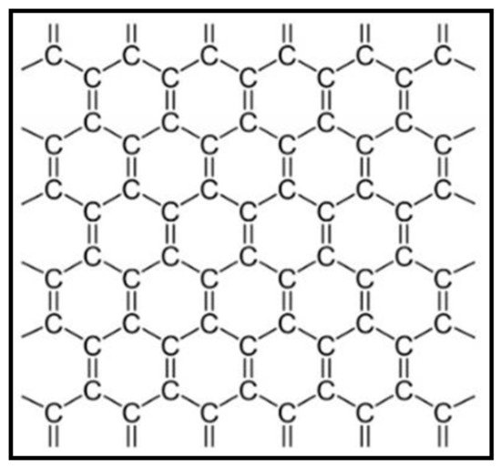
Figure 1. Graphene structure.
Technically, it is a non-metal material but it is deemed a quasi-metal because it displays semi-conducting metal properties. Graphene possesses unique properties which do not exist in other non-metallic materials, therefore making it superlative material for electronic applications usage. The single-layer graphene sheet has 1.0 TPa Young’s modulus and can bear stress up to 42 Nm−1, that is why it is considered as one of the strongest materials available [55]. The electron mobility of graphene in comparison to silicon is 100 times faster and it conducts twice as much heat as diamond. The electrical conductivity of graphene in comparison to copper is 13 times better [56]. The graphene family that has been used as EMI shielding material are presented in Figure 2. The types of graphene are distinguished based on their structure. The modification has been brought into the material by altering the structural properties.
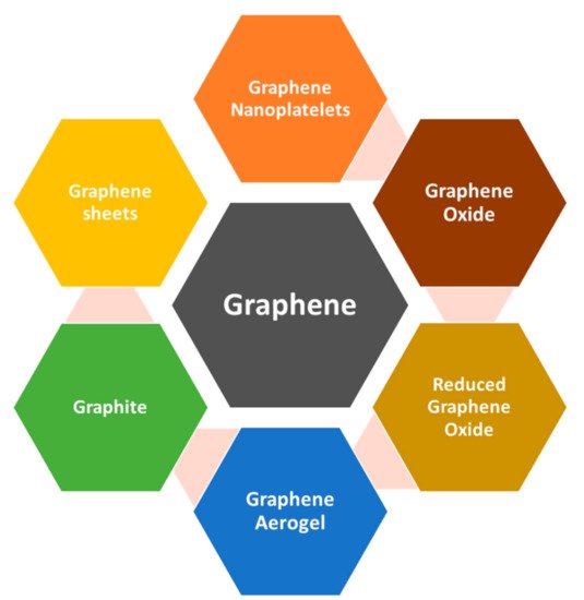
Figure 2. Graphene family for EMI shielding.
Among metals, iron has gained much popularity due to its magnificent properties to deal with EMI. In recent years magnetic nanostructures are in demand as they provide good absorption when combined with graphene. In comparison to other metals for EMI shielding applications, iron is the most desirable material due to its high natural availability, low facile synthesis cost and high biocompatibility and biodegradability nature [57]. The various types of iron which have been used extensively in the field of EMI are presented in Figure 3. which is adapted from [57].
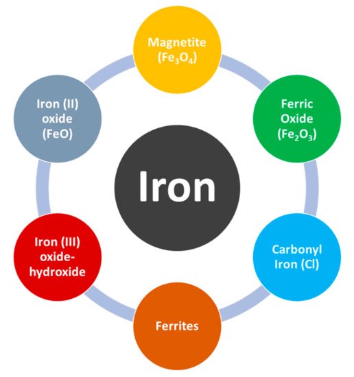
Figure 3. Iron component types.
2.1. Graphene@Iron Composites
2.1.1. Keywords Analysis of Graphene@Iron Composites Articles
Keywords analysis is important in evaluating the area of interest in the articles. It helps to identify the differences and research growth in a particular studied area. Moreover, the co-occurrence analysis of keywords shows the relationship build due to various keywords. Based on the selected articles of Graphene@Iron composites, keyword analysis of the selected articles was made by VOSviewer where the mapping is shown in Figure 4.
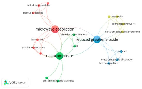
Figure 4. Keyword Analysis of Graphene@Iron-based composites articles.
The first cluster with red nodes was assembled across the term “microwave absorption” having a maximum occurrence of 3. In the same cluster, “Fe3O4 nanoparticles”, “ferric oxide”, “graphene nanoplate”, “hybrid material”, “impedance matching”, “microwave absorption”, “porous graphene” exists with just one occurrence each. The following cluster demonstrates the interest of researchers in microwave absorption of the included composites.
Similarly, the green cluster around the keyword “nanocomposite” having a maximum cooccurrence of 3. The same cluster consists of keywords “EMI shielding effectiveness”, “Fe3O4 @gnp hybrid”, “nanocomposite”, “shielding effectiveness” and “spinel”. Likewise, the third cluster is blue coloured with the keyword “reduced graphene oxide” with a maximum occurrence of 3. While the last yellow cluster is closely linked with the blue cluster having keywords “electromagnetic interference shielding”, “magnetite”, “natural rubber” and “segregated network” with 1 occurrence each.
2.1.2. Interpretation of Graphene@Iron Composites Articles
Different types of graphene such as pristine graphene, reduced graphene oxide, and graphene oxide have been investigated for EMI shielding alone and at times as a combination with other materials which possess conductive and magnetic properties [46][58][59][60]. Being a 2D nanomaterial, graphene has remarkable electrical properties that is why it has been used extensively for EMI shielding. With iron and graphene combinations researchers introduce a third material to enhance their properties such as epoxy, polymer, silicon dioxide (SiO2), titanium dioxide (TiO2) etc. The work is still going on with different formed combination to deliver quality results.
Wang et al. [61] used a hydrothermal method to fabricate hollow ZnFe2O4 microspheres@graphene which was decorated with TiO2 nanosheets. The highest reflection loss of ZnFe2O4@graphene@TiO2 with the coating of 2.5 mm was up to −55.6 dB at 3.8 GHz, where the absorbing bandwidth surpassing −10 dB at 6.4 GHz with the same thickness. The results prove that ZnFe2O4@graphene@TiO2 provides good absorption in low frequency. Mederos-Henry et al. [62] conducted a study on low frequency microwaves using the Pechini sol-gel method, where a new microwave absorber material was synthesized having the combination of reduced graphene oxide which was covered with Fe@ϒ-Fe2O3 and Fe/Co/Ni. It was revealed that the microwave absorption efficiency (0.4 MHz–20 GHz) comes in the range of 60%–100% by using these materials, depending on the metallic particles’ nature grafted on reduced graphene oxide. Chen et al. [63] adopted a scalable coprecipitation process to form aerogels exhibiting strong electromagnetic wave absorption material using cellulose/reduced graphene oxide and Fe3O4 with the loading of 8 wt.% and 15 wt.%. With the aerogel thickness of 0.5 mm, 32.4–40.1 dB EMI shielding effectiveness was achieved for 8.2–12.4 GHz frequency. The shielding effectiveness got higher by introducing a larger amount of reduced graphene oxide with loading varies between 3–8 wt.% and increasing the thickness between 0.5–2 mm. Shielding effectiveness reached 49.4–52.4 dB with 2 mm sample thickness. It was concluded that high shielding effectiveness can be achieved with the help of lightweight aerogels.
Kumar et al. [64] utilized a solvothermal method to synthesize the NiFe2O4 nanoparticles with reduced graphene oxide to observed EMI shielding performance within the frequency range of 8.2–12.4 GHz. Significant dielectric and magnetic loss were shown by the nanocomposite compared to RGO with improvement in electromagnetic wave absorption. With 2 mm thickness, the shielding effectiveness of 38.2 dB at 10.8 GHz was achieved with a 35/65 ratio of NiFe2O4/RGO. Prasad et al. [65] decorated magnetic CoFe₂O₄ nanoparticles on MoS₂-reduced graphene oxide surface using hydrothermal method. The EMI shielding effectiveness was examined within the range of 8.0–12.0 GHz, where the pure MoS₂-RGO nanocomposite gives shielding effectiveness of 16.52 dB while the MoS₂-RGO/CoFe₂O₄ nanocomposite provides shielding effectiveness of 19.26 dB.
Jiang et al. [66] used a facile solvothermal method for developing a magnetic Fe3O4 combined with graphene nanoplates by constructing spherical Fe3O4 particles with integrity crystal on the graphene sheet surface. The results showed a better absorption performance due to the impedance matching ability of Fe3O4@f-GNPs compared to dielectric f-GNPs and magnetic Fe3O4, with a reflection loss of −25 dB at 10 GHz frequency when having 2 mm sample thickness and 2.4 GHz (below −10 dB) effective absorption bandwidth. Moreover, the absorption and total efficiencies were 32 dB and 25 dB respectively, when the Fe3O4@f-GNPs exhibited shielding efficiency properties with 232 nm Fe3O4 in the X band. Bhaskaran et al. [67] investigated the EMI shielding effectiveness of epoxy nanocomposites containing Fe3O4 nanoparticles coated graphene nanoplatelets, where by using a co-precipitation technique and a solvent-less approach, hybrid nanostructures were synthesized in situ. The results showed the high EMI shielding effectiveness of Fe3O4@GNP compared to other samples having equivalent loading of GNP and Fe3O4. The sample containing a 1:3 ratio of Fe3O4:GNP hybrid with 1 mm thickness reduced incident wave power up to 89% with EMI shielding effectiveness of 9.6 dB. Fei et al. [68] fabricated a multilayer sandwich structure from graphene nanoplates (GNPs), ferric metal-organic frameworks (MOFs) (MIL-88B)-derived magnetic carbon-based materials (C-MIL-88B) via a filtration assisted self-assembly method. With the insertion of Fe3O4-C, C-MIL-88B/GNP adequate results in terms of magnetization and conductivity were shown, where the composite film consisting of five layers with the thickness of 0.12 mm showed effective EMI shielding with the value of 28 dB in the X-band frequency range with 86% of power coefficient absorption. Zheng et al. [69] synthesized porous graphene (PG) with Fe3O4 via in situ growth. It was revealed that PG-Fe3O4 provides excellent microwave absorption where the reflection loss came as −53 dB at 5.4 GHz frequency. PG which is formed by structure modification is important in achieving the results and showed better performance when get compared with the ordinary graphene.
Graphene oxide (GO) was synthesized with carbonyl iron particles (CIP) by the wet stirring process. The shielding effectiveness of the composite was examined within the range of 0–18 GHz where the maximum reflection loss of −56.4 dB was achieved while keeping the thickness as 1.9 mm. The composite is proposed to be used in X-band as well as Ku-band [70]. Ag@Fe3O4 was synthesized with reduced graphene oxide by using the solvothermal method. In the testing range (2–18 GHz) the maximum reflection loss came as −40.05 dB at 11.9 GHz [71]. In another study, Fe3O4@C/RGO was synthesized using the solvothermal method where the reflection loss of −59.23 dB was achieved at 6.24 GHz within the frequency range of 2–18 GHz while keeping the thickness at 3.57 mm [72]. Zhang et al. [73] synthesized natural rubber with magnetic iron oxide and reduced graphene oxide, forming an NRMG composite. The shielding effectiveness of 26.4 dB was achieved within the testing range of X-band while keeping the sample thickness as 1.6 mm. Zhang et al. [73] synthesized graphene and Fe3O4 with carbon (C) nanoparticles to form a shielding composite. The reflection loss of −55.05 dB was achieved within the 2–18 GHz frequency range. Liu et al. [74] synthesized magnetic graphene (G) with Fe3O4 (F) hybrid material via the hydrothermal method. The shielding effectiveness was tested within the 2–18 GHz frequency range. While keeping the sample thickness as 1.9 mm, shielding effectiveness of 20 dB was achieved. Yin et al. [75] Ni0.5Co0.5Fe2O4/graphene via a hydrothermal method to form a shielding composite, where it was tested within the range of 0.58–1.19 GHz. A reflection loss of −30.92 dB was achieved at 0.84 GHz with 4 mm thickness. Guo et al. [76] utilized a vacuum-assisted filtration method to form a shielding composite of RGO/CNF@Ag-Fe3O4, where shielding effectiveness of 21 dB was achieved in X-band frequency range with 0.11 mm sample thickness. Table 1 shows a summary of graphene and iron-based composites.
Table 1. Summary of Graphene@Iron-based composites.
| S. No | Material | Thickness | Loading | Methods | Frequency | Shielding Effectiveness | Year | Reference |
|---|---|---|---|---|---|---|---|---|
| 1 | ZnFe2O4@graphene@TiO2 | 2.5 mm | - | Hydrothermal method | 3.8 GHz | −55 dB | 2017 | [61] |
| 2 | Cellulose/reduced graphene oxide (RGO)/Fe3O4 aerogels | 0.5 mm | 3 wt.% | Scalable method | 8–12 GHz | 49.4 dB | 2020 | [63] |
| 2 mm | 8 wt.% | 52.4 dB | ||||||
| 3 | NiFe2O4/RGO | 2 mm | - | Solvothermal method | 10.8 GHz | 38.2 dB | 2020 | [64] |
| 4 | MoS₂-RGO/CoFe₂O₄ | 1.4 mm | - | Hydrothermal method | 8–12 GHz | 19.26 dB | 2019 | [65] |
| 5 | Fe3O4@GNP hybrids | 1 mm | - | 1. Co-precipitation technique 2. Solvent-less approach |
8–12 GHz | 9.6 dB | 2020 | [67] |
| 6 | Fe3O4-C, C-MIL-88B/GNP | 0.11 mm | - | Filtration-assisted self-assembly method | 8–12 GHz | 28 dB | 2019 | [68] |
| 7 | Fe3O4@f-GNPs | 2 mm | - | Solvothermal method | 12 GHz | 25 dB | 2020 | [66] |
| 8 | PG-Fe3O4 | 6.1 mm | - | In-situ growth | 5.4 GHz | −53 dB | 2017 | [69] |
| 9 | GO@CIP | 1.9 mm | - | Wet stirring process | 0–18 GHz | −56.4 dB | 2019 | [70] |
| 10 | Ag@Fe3O4@RGO | 2 mm | - | Solvothermal method | 2–18 GHz | −40.05 dB | 2015 | [71] |
| 11 | Fe3O4@C/RGO | 3.57 mm | - | Solvothermal method | 2–18 GHz | −59.23 dB | 2020 | [72] |
| 12 | NRMG | 1.6 mm | - | Self-assembly method | 8–12 GHz | 26.4 dB | 2018 | [73] |
| 13 | Fe3O4@C@Graphene | 1.5 mm | - | Hydrothermal method | 2–18 GHz | −55.02 dB | 2018 | [73] |
| 14 | G-F | 1.9 mm | - | Hydrothermal method | 2–18 GHz | 20 dB | 2016 | [74] |
| 15 | Ni0.5Co0.5Fe2O4/graphene | 4 mm | - | Hydrothermal method | 0.58–1.19 GHz | −30.92 dB | 2018 | [75] |
| 16 | RGO/CNF@Ag-Fe3O4 | 0.11 mm | - | Vacuum-assisted filtration method | 8–12 GHz | 21 dB | 2020 | [76] |
3. Polymer-Based Composites
Metals have extensively been utilized for EMI shielding, however, due to easy corrosion and difficult processing, their use has been limited [77][78]. Therefore, researchers turned their interest towards an alternative material i.e., polymer-based composites, which are more promising as they are lightweight, having a low cost, more processability and give better performance as compared to metal-based composites [79][80]. Polymer-conductive nanoparticle composite has unique porous morphology which has shown better results as electromagnetic waves absorber. Air insertion in the material permits high electromagnetic waves access which expands interactions with various air-filled pores and high conductive cell walls. As a result, effective electromagnetic wave dissipation occurred within a lightweight structure. It has a massive influence on final shielding properties however the relationship between final morphology and foaming conditions differs and not certainly predictable [81]. Polymer-based composite materials provide exceptional benefits in comparison to metals, such as low density, enhanced flexibility, and ease in processing. However, with limited mechanical properties like inadequate electrical conductivity, lower temperature resistance, it is difficult to utilize polymer for shielding applications, especially under extreme temperature [82]. Hence, such a combination should be created which can overcome the deficiencies of polymer against electromagnetic wave shielding in extreme conditions.
3.1. Graphene@Iron@Polymer Composites
3.1.1. Keywords Analysis of Graphene@Iron@Polymer Composites Articles
Based on the selected articles of Graphene@Iron@Polymer composites, keyword analysis of the selected articles was made by VOSviewer where the mapping is shown in Figure 5.
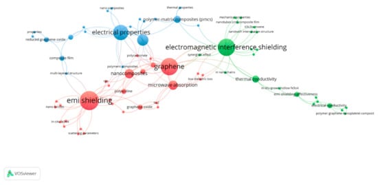
Figure 5. Keywords Analysis of polymer-based composite articles.
The first cluster with red nodes was assembled across the term “EMI shielding” and “graphene” having a maximum occurrence of nine and eight, respectively. In the same cluster, the terms “nano composites” and “microwave absorption” with an occurrence of four can be seen. The second cluster with green nodes is representing the second large cluster assembled around the most frequently used term “electromagnetic interference shielding” with the occurrence of eight. This cluster consists of some main words such as: “synergistic effect”, having three occurrences and “EMI shielding effectiveness” with two occurrences. There are also some other keywords relating to the properties such as “magnetic nanoparticles”, “ultrathin film” and “mechanical properties” which shows that the researchers interested in studying the properties of polymers. The third cluster with blue nodes was assembled around “electrical properties” having seven occurrences. This cluster is enriched with many polymers keywords such as “polymers”, “polymer-matrix composites (PMCs)”, “reduced graphene oxide” and many more indicating the study of shielding effect of these polymers and their properties with different parameters.
3.1.2. Interpretation of Graphene@Iron@Polymer Based Composites Articles
Different fillers are used with polymer composites to enhance the underlying matrix material. Carbonaceous fillers such as carbon black, carbon nanotubes, carbon nanofibers, graphene and graphene nanoplates have shown benefits in improving the mechanical properties of polymer composites [83][84]. Adding graphene to a polymer has been shown to result in effective EMI shielding properties as it has the capability to create conductive networks within the polymer matrix [85][86][87]. In addition to improved filler materials, polyaniline (PANI) comes as the matrix material [88]. Shakir et al. [89] evaluated EMI shielding properties by utilizing polymer blends of polyvinyl chloride (PVC) and PANI with graphene nanoplatelets (GNP) insertion. An enhanced electrical conductivity was noticed both for PVC/PANI and PVC/PANI/GNP composites. The EMI shielding effectiveness of 51 dB was achieved in the 18–20 GHz range. Khasim [90] used PANI and graphene nanoplatelet composite for microwave shielding applications. The composite was prepared keeping 1.5 mm thickness by using in-situ polymerization. It was revealed that with 10 wt.% loading of graphene nanoplatelet, high shielding effectiveness (up to 95%) was achieved in X-band frequency. Also, it was revealed that the high absorption occurs due to the dominant absorption mechanism. Having improved conductivity, better thermal stability, and excellent EMI shielding properties, the composite is recommended for its application in X-band microwave frequencies. Jia et al. [91] formed TiO2/PANI/Graphene oxide (GO) composite via in-situ growth. The reflection loss was examined within the range of 2–18 GHz where the maximum came as −51.74 dB at 9.67 GHz frequency. Liu et al. [92] used in-situ growth and hydrothermal method to synthesize magnetic graphene with PANI and porous TiO2 and tested its EMI shielding efficiency within the range of 2–18 GHz. Keeping the sample thickness as 1.5 mm, a reflection loss of −45.4 dB was achieved.
Wang et al. [93] synthesized graphene@Fe3O4@PANI decorated with WO3 particles by using a hydrothermal method and chemical oxidation polymerization. The spherical nanoparticles of Fe3O4 and WO3 having a diameter of 300–500 nm and 50–150 nm were spread in between graphene@PANI layers. The results showed that graphene@Fe3O4@PANI@WO3 gives better electromagnetic wave absorption as compared to graphene@Fe3O4 and graphene@Fe3O4@PANI, where maximum achieved absorption was −46.7 dB with a coating thickness of 4 mm. Whereas, the maximum absorbing bandwidth was ≤10 dB of 1.8 GHz (from 12.4 to 14.2 GHz) with a thickness of 1.5 mm. Wang et al. [94] fabricated a graphene@Fe3O4@SiO2@polyaniline composite which gives better reflection loss of −40 dB at 12.5 GHz with 2.5 mm thickness and absorption bandwidth below −10 dB of 5.8 GHz (from 10.5 to 16.5 GHz) when compared with graphene@Fe3O4. Zhao et al. [95] used the Hummers method to synthesized polyaniline (PANI), graphene oxide (GO) and Fe3O4 as EMI shielding composite. With a sample thickness of 3.91 mm, a reflection loss of −53.5 dB was observed within the range of the 2–18 GHz frequency.
In another study, PANI composite comprised of graphene and silver nanoparticles were used as EMI shielding material where the shielding effectiveness of 29.33 dB in 0.4–1.6 GHz frequency range was achieved at 5 wt.% loading [96]. Ma et al. [97] formed Fe3O4/PANI rod/RGO composites to deal with the EMI which was tested under the range of 2–18 GHz where a reflection loss of −33.3 GHz was achieved. In the study, the material thickness was increased from 1 mm to 4 mm where the maximum reflection loss was achieved at 3.5 mm thickness. It proves that by increasing the sample thickness the shielding effectiveness can be increased but up to a certain level. Wang et al. [98] synthesized graphene@NiO@PANI@Ag using hydrothermal and in-situ growth method. The composite material was tested within the range of 2–18 GHz where a reflection loss was achieved as −37.5 dB with 3.5 mm sample thickness. Zhou et al. [99] formed graphene-doped polyaniline (G-PANI) as shielding composite via in-situ growth. The shielding effectiveness of 32.5 dB was achieved within the range of 2–18 GHz with 1.5 mm thickness. Singh et al. [100] formed a new material ℽ-Fe2O3 and decorated it with RGO and PANI to observe the shielding efficiency of the composite. The composite was formed via chemical oxidation polymerization and in-situ growth and tested within the X-band frequency range. While keeping the sample thickness as 2.5 mm, total shielding effectiveness of 51 dB was achieved. Wang et al. [101] explored Ti3C2Tx MXene shielding properties by making its composite with Fe3O4 and PANI polymer. The co-precipitation method was used to prepare the composite and was tested within the X-band frequency range. Shielding effectiveness of 58.8 dB was achieved with 12.1 µm sample thickness. Preeti et al. [102] used the citrate precursor method to synthesize RGO, barium ferrite (BF) and PANI to form a shielding composite where shielding effectiveness of 31.1 dB was achieved in the X-band frequency range. Dar et al. [103] synthesized PANI/Li0.5Fe0.5−xGdxO4 via in-situ growth where the composite was tested within the X-band frequency range. Keeping the sample thickness as 0.2 mm, shielding effectiveness of 42 dB was achieved.
Yan et al. [80] evaluated ultra-efficient electromagnetic interference shielding by using reduced graphene oxide and polystyrene. The results showed that with 3.47 vol% of RGO-based polymer composite, 45.1 dB shielding effectiveness was achieved. Shahzad et al. [104] formed two different composites via a hot compressed method. One was segregated RGO with polystyrene (PS) and the other was conventional RGO/PS. The testing was made from 0–20 GHz where the shielding effectiveness of 29.7 dB and 14.2 dB was achieved with 2 mm sample thickness. Nimbalkar et al. [105] formed a composite by optimizing polycarbonate and graphene nanoplatelets (GNP), using the facile solution method, for electromagnetic interference shielding in X-band. Keeping the composite thickness as 1 mm, 35 dB shielding effectiveness was achieved, where, by increasing the thickness up to 2 mm, 47 dB shielding effectiveness was achieved, indicating that the increase in the thickness directly enhances the shielding effectiveness. Hamidinejad et al. [106] examined lightweight high-density polyethylene (HDPE) with graphene nanoplatelets composites which were fabricated using the supercritical fluid and injection moulding process. The shielding effectiveness of 31.6 dB was achieved in K-band. Lu et al. [107] fabricated ethylene propylene diene monomer rubber (EPDM) with graphene nanoplatelets loading to observed EMI shielding effectiveness in X-band and Ku-band. The results showed that with 8 wt.% of GNP, keeping thickness 0.3 mm, 33 dB shielding effectiveness was achieved in X-band, whereas, in Ku-band, 35 dB shielding effectiveness was achieved.
Zdrojek et al. [108] conducted a study on sub-terahertz radiation shielding by using a graphene-based plastic absorber where PDMS polymer was used. It was observed that being lightweight and nonconductive, graphene-based composites can absorb 99.99% of electromagnetic waves, whereas most metal-based composites simply redirect the radiations. Li et al. [109] formed a copper-coated RGO@PDMS polymer composite by the Hummers method, where a shielding effectiveness of 74.2 dB was achieved in the X-band frequency range. Ni et al. [110] synthesized a graphene aerogel (GA) with PDMS polymer, where shielding effectiveness of 60 dB was achieved within the frequency range of 2–18 GHz. In another study conducted by Fang et al. [111], a 3D-graphene network combined with PDMS was used for high performance EMI shielding. With this combination, 6100 S/m electrical conductivity was achieved even with a low graphene loading of 1.2 wt.%. Also, around 40 and 90 dB, EMI shielding effectiveness was attained in the X-band range when the thickness was kept as 0.25 and 0.75 mm. It is noteworthy that with a 1.2 wt.% loading level, a 256% increase was observed in the tensile strength of the composite. Fang et al. [111] formed a composite of in-situ grown hollow Fe3O4 with graphene foam (GF) and PDMS by using the solvothermal method for high EMI shielding effectiveness. The results showed that 70.37 dB shielding effectiveness was achieved in the X-band frequency. Nguyen et al. [112] worked on multifunctional broadband EMI shielding skins using MXene(Ti3C2TX)/graphene/PDMS composites. MXene is a newly developed shielding material that provides high shielding effectiveness [113]. Fe3O4 nanoparticles added with Ti3C2TX was coated on graphene foams, where the thickness was kept as 1 mm. The results revealed that an excellent EMI shielding effectiveness was achieved in X-band with 80 dB, whereas, in Ka-band, 77 dB shielding effectiveness was achieved. Liang et al. [114] optimized flexible polyvinylidene fluoride (PVDF) with high-aligned graphene nanosheets and Ni nanochains for EMI shielding. With sample thickness kept as 0.5 mm in K-band range, 43.3 dB shielding effectiveness was achieved. Whereas, by increasing the thickness up to 0.7 mm, 51.4 dB shielding effectiveness was achieved within the same frequency range. Sharma et al. [115] grow copper sulphide (CuS) flowers on graphene oxide and later mix it with PVDF polymer. The composites showed shielding effectiveness up to −25 dB at the 12–18 GHz frequency range. Multi-layered graphene nanosheets synthesized with Fe3O4 and PVDF showed better results where shielding effectiveness of 52 dB was achieved at X-band frequency range while keeping the sample thickness as 0.3 mm [116]. With in-situ growth, RGO and hematite nanohybrids were synthesized with the addition of PVDF. While keeping its loading as 5 wt.%, the maximum absorbing value of −43.97 dB was achieved at 5 GHz [117]. Liang et al. [118] synthesized graphene (Gn) and silicon carbide nanowires (SiCnw) with PVDF via electrostatic assembly and solution casting method. Shielding effectiveness of 32.5 dB was achieved with 1.2 mm sample thickness when tested in the X-band frequency range. Sabira et al. [119] synthesized PVDF with graphene nanocomposite via a solution casting method. Shielding effectiveness of 47 dB was achieved within the X-band frequency range with 20 µm thickness. Qi et al. [120] worked on the three-layered sandwich structure of PVDF, graphene nanoplatelets, nickel (Ni) and carbon nanotubes (CNT). The composite was tested for a three-layered and six-layered structure where shielding effectiveness of 41.8 dB and 46.4 dB was achieved at 15 GHz with a fixed thickness of 0.6 mm. Gargama et al. [121] synthesized PVDF with nanocrystalline iron (n-Fe) to form a shielding composite which was tested within the X-band frequency range. The composite provided shielding effectiveness of 40.21 dB with a 1.93 mm thickness sample. PVDF was also synthesized with ferrosoferric oxide decorated polyaniline/single wall carbon nanohorn (PFC) to form a shielding composite. A reflection loss of −29.7 dB appeared within the Ku-band with 2 mm thickness [122].
Liang et al. [114] optimized 3D copper nanowires-thermally annealed graphene aerogel (CuNWs-TAGA) with epoxy by a thermal annealing method. While keeping the loading of CuNWs-TAGA as 7.2 wt.%, shielding effectiveness was achieved up to 47 dB in the X-band frequency range. Wu et al. [123] synthesized RGO modified carbon fibre (RGO-CF) with the addition of epoxy (EP) using chemical reduction and electrophoretic deposition methods. With a thickness of 3–5 mm, the maximum shielding effectiveness of 37.6 dB was achieved within the X-band frequency range. Liu et al. [124] synthesized 3D network porous graphene nanoplatelets (GNP) with Fe3O4 and epoxy to form a shielding composite. With 7 wt.% loading of GNP and Fe3O4, 37.03 dB shielding effectiveness was achieved in the X-band frequency range. A three-phase composite (graphite nanoplatelets (GNP)/carbonyl iron (Fe)/epoxy) was fabricated using a sonication method. The shielding effectiveness was evaluated from 1–67 GHz with various thickness and loadings. It was observed that with 5 mm thickness of the sample and 5 wt.% GNP loading, the reflection loss came as −78 dB [125]. Chen et al. [126] optimized thermally reduced graphene oxide (TGO), magnetic carbonyl iron (CI) and epoxy. The composite was tested in the X-band range where shielding effectiveness of 40 dB was achieved at 4 mm thickness.
Wu et al. [127] synthesized graphene carbon filler (GCF), with magnetic graphene (MG) and epoxy (EP) to form a shielding composite where GCF loading was 0.5 wt.% and MG loading was 9 wt.%. The testing range was from 18–26 GHz where shielding effectiveness of 51.1 dB was achieved. Jaiswal et al. [128] synthesized reduced graphene oxide and ferrite nanofiller with epoxy to form a shielding composite. While keeping the epoxy loading as 60 wt.%, a reflection loss of −10.26 dB was achieved with a 3 mm sample thickness in the 2–18 GHz frequency range. Tolvanen et al. [129] synthesized biodegradable multiphase polylactic acid with biochar and graphite using the hot-pressing method. The composite was tested within the frequency range of K-band where the shielding effectiveness was achieved as 30 dB while using the thin films of 0.25 mm thickness. Barium strontium titanate (BST) was synthesized with RGO and Fe3O4 with the addition of polypyrrole polymer via chemical oxidative polymerization. The testing was made within the X-band frequency range where the shielding effectiveness of 48 dB was achieved [130]. Using the Hummers method, RGO and polyetherimide (PEI) polymer were synthesized to form a shielding composite that was tested in the range of X-band frequency. With the RGO loading of 2.5 wt.%, the maximum shielding effectiveness of 26 dB was achieved [131].
Hong et al. [132] evaluated the anisotropic EMI shielding effectiveness of polymer-based composites. Magnetic responsive reduced graphene oxide (Fe3O4@RGO) as filler material was synthesized for controlling the orientation of reduced graphene oxide in thermoplastic polyurethane (TPU), where the magnetic field was applied to control the orientation of Fe3O4@RGO in in-plane and out-plane direction. A comparison was made between aligned Fe3O4@RGO/TPU, random Fe3O4@RGO/TPU and random RGO/TPU composites. Results revealed that the random Fe3O4@RGO/TPU composites shown an increase in EMI shielding effectiveness by 224% over random RGO/TPU composites. Whereas in-plane aligned Fe3O4@RGO showed 250% improved EMI shielding effectiveness over random RGO/TPU composites. The results proved that in determining the EMI shielding effectiveness, the orientation of fillers plays a vital role. Hu et al. [133] synthesized graphene sponge (G) with polyurethane to form a shielding composite. With a sample thickness of 9 mm and graphene loading 18.7 wt.% shielding effectiveness of 35 dB was achieved in the X-band frequency range. In another study, TPU was synthesized with thermally reduced graphene nanosheets (TRG) via the solution blending method and was tested for its shielding efficiency in Ku-band. The concentration of TRG was from 0 to 5.5 vol% where the maximum total shielding effectiveness was achieved as 32 dB at 5.5 vol% while keeping the sample thickness as 2 mm [134]. Zubair et al. [135] synthesized thermally reduced graphene oxide (TRGO) and barium hexaferrite (BaFe) with thermoplastic TPU via the solution casting method. While keeping the sample thickness as 0.25 mm, EMI shielding effectiveness of -61 dB was achieved at 12.5 GHz frequency.
Poly(3,4-ethylenedioxythiophene) (PEDOT) was synthesized with RGO and SrFe12O19 nanoparticles through in-situ growth. The EMI shielding composite was tested in the X-band range where the shielding effectiveness of 42.29 dB was achieved with 2.5 mm thickness and 62 dB with 4.66 mm thickness [136]. PEDOT and RGO were also synthesized with PbTiO3 via chemical oxidative polymerization where the shielding effectiveness of 51.94 dB was achieved within the frequency range of 12.4–18 GHz at 2.5 mm thickness [137]. In another study PEDOT:PSS was synthesized with Fe3O4 and RGO to form a shielding composite. The testing was made within the range of 2–18 GHz where the maximum reflection loss of −61.4 dB was achieved with 3.86 mm sample thickness [138]. Shukla [139] synthesized Fe3O4 with carbon (C) and polypyrrole (PPy) via hydrothermal and chemical oxidative polymerization to form a shielding composite. It was observed that by keeping the carbon loading up to 2 wt.% and PPy up to 8 wt.%, with the sample thickness 0.8 mm, shielding effectiveness > 28 dB was achieved at 2–8 GHz frequency range. In another study, polypyrrole was used with FeCo and RGO to form a shielding composite via a three-step method. The testing was made within the range of 2–18 GHz where the maximum reflection loss of −40.7 dB was attained at 4.5 GHz when the sample thickness was 2.5 mm [140]. Yan et al. [141] optimized three different polymer-based composites i.e., RGO-PANI-NiFe2O4, RGO-PPy-NiFe2O4 and RGO-PEDOT-NiFe2O4. With a material thickness of 2.4 mm, 1.7 mm and 2 mm, a reflection loss of −49.7 dB, −44.8 dB and −45.4 dB was achieved within the 2–18 GHz frequency range. It can be observed that the highest reflection loss was achieved by the PANI polymer composite.
Zuo et al. [142] synthesized polymethyl methacrylate (PMMA) with graphene and Li0.35Zn0.3Fe2.35O4 where the testing was made within the range of 2–18 GHz. A reflection loss of −46.1 dB was achieved with 4 mm thickness. Sharif et al. [143] optimized PMMA and RGO to form a shielding composite where the testing was made within the X-band. With 2.9 mm sample thickness and 2.6 vol% RGO, shielding effectiveness of 63.2 dB was achieved. Joseph et al. [144] synthesized two different polymer composites for EMI shielding. The first combination was of PMMA with graphene, whereas, the second combination was of polyvinyl chloride (PVC). The shielding effectiveness of 21 dB and 31 dB was achieved within the X-band frequency range with sample thickness as 2 mm and graphene loading as 20 wt.%.
Rao et al. [145] synthesized Fe3O4 with single-layer graphene-assembled porous carbon (SLGAPC) and polyvinyl alcohol (PVA) via the solution casting method. With a thickness of 0.3 mm, the shielding effectiveness of 20 dB was achieved in the X-band frequency range. Khodiri et al. [146] used PVA, graphene (Gr) and magnetite (Fe3O4) to form a shielding composite. With 0.2 mm thickness and little graphene loading of 0.08 wt.%, shielding effectiveness of 40.7 dB was achieved within the X-band frequency range. Li et al. [147] explored polyether-ether-ketone (PEEK) polymer with GNP and carbonized loofah fibre (CLF) to form a shielding composite. Keeping the testing within X-band, shielding effectiveness of 27.1 dB was achieved with 9 wt.% of CLF. Yadav et al. [148] used NiFe2O4, RGO and polypropylene to form a shielding composite. The testing was in the range of 6-8 GHz where high shielding effectiveness of 29.4 dB was achieved with 2 mm thickness and 5 wt.% RGO loading. Table 2 shows a summary of polymer-based composites.
Table 2. Summary of Polymer-based composites.
| S. No | Material | Thickness | Loading | Methods | Frequency | Shielding Effectiveness | Year | Reference |
|---|---|---|---|---|---|---|---|---|
| 1 | PVC/PANI/GNP | - | 5 wt.% | Solution processing method | 18–20 GHz | 51 dB | 2019 | [89] |
| 2 | GNP@PANI | 1.5 mm | - | In-situ growth | 12 GHz | −14.5 dB | 2019 | [90] |
| 3 | TiO2/PANI/GO | 3.12 mm | - | In-situ growth | 2–18 GHz | −51.7 dB | 2017 | [91] |
| 4 | Graphene@PANI@TiO2 | 1.5 mm | - | 1. In-situ growth 2. Hydrothermal method |
2–18 GHz | −45.4 dB | 2016 | [92] |
| 5 | Graphene@Fe3O4@PANI@WO3 | 4 mm | - | 1. Hydrothermal method 2. Chemical oxidation polymerization |
9.4 GHz | −46.7 dB | 2017 | [93] |
| 6 | Graphene@Fe3O4@SiO2@polyaniline | 2.5 mm | - | Dilute polymerization | 12.5 GHz | −40.7 dB | 2015 | [94] |
| 7 | PANI/GO/Fe3O4 | 3.91 mm | - | Hummers method | 2–18 GHz | −53.5 dB | 2015 | [95] |
| 8 | Ag@Graphene/PANI | - | 5 wt.% | In-situ growth | 0.4–1.6 GHz | 29.33 dB | 2013 | [96] |
| 9 | Fe3O4/PANI rod/RGO | 3.5 mm | - | Facile method | 2–18 GHz | −33.3 dB | 2019 | [97] |
| 10 | Graphene@NiO@PANI@Ag | 3.5 mm | - | 1. Hydrothermal method 2. In-situ growth |
2–18 GHz | −37.5 dB | 2017 | [98] |
| 11 | G-PANI | 1.5 mm | - | In-situ growth | 2–18 GHz | 32.5 dB | 2017 | [99] |
| 12 | ℽ-Fe2O3/RGO/PANI | 2.5 mm | - | 1. Chemical oxidation polymerization 2. In-situ growth |
8–12 GHz | 51 dB | 2014 | [100] |
| 13 | Ti3C2Tx/Fe3O4@PANI | 12.1 µm | - | Co-precipitation method |
8–12 GHz | 58.8 dB | 2020 | [101] |
| 14 | PANI/BF/RGO | - | - | Citrate precursor method | 8–12 GHz | 31.1 dB | 2016 | [102] |
| 15 | PANI/Li0.5Fe0.5-xGdxO4 | 2 mm | - | In-situ growth | 8–12 GHz | 42 dB | 2019 | [103] |
| 16 | RGO@polystyrene | - | 3.47 vol% | High-pressure solid-phase compression moulding | 8–12 GHz | 45.1 dB | 2015 | [80] |
| 17 | Segregated RGO/PS | 2 mm | 10 wt.% | Hot compressed method | 0–20 GHz | 29.7 dB | 2018 | [104] |
| Conventional RGO/PS | 14.2 dB | |||||||
| 18 | Polycarbonate/GNP | 1 mm | - | Facile solution method | 8–12 GHz | 35 dB | 2018 | [105] |
| 2 mm | - | 47 dB | ||||||
| 19 | Polyethylene@GNP | - | 15.6 vol% | Injection moulding process | 18 and 26.5 GHz | 16 dB | 2018 | [106] |
| 19 vol% | 31.6 dB | |||||||
| 3 wt.% | 12 dB | |||||||
| 10 wt.% | 31 dB | |||||||
| 20 | GNP/EPDM | 0.3 mm | 8 wt.% | Ultrasonication technique | 8–12 GHz | 33 dB | 2019 | [107] |
| 12.4–18 GHz | 35 dB | |||||||
| 21 | Hollow Fe3O4@GF@PDMS | - | 4 wt.% | Solvothermal method | 8–12 GHz | 45 dB | 2020 | [111] |
| 8 wt.% | 65 dB | |||||||
| 12 wt.% | 70.3 dB | |||||||
| 22 | 3D Graphene Network@PDMS | 0.25 mm | 1.2 wt.% | Chemical vapor deposition | 8–12 GHz | 40 dB | 2020 | [111] |
| 0.75 mm | 90 dB | |||||||
| 23 | MXene(Ti3C2TX)/graphene/PDMS | 1 mm | - | Chemical vapor deposition | 8–12 GHz | 80 dB | 2020 | [112] |
| 26.5–40 GHz | 77 dB | |||||||
| 24 | Graphene flakes@PDMS | - | 0.1 wt.% | Mechanical mixing | 0.6 THz | 6.5 dB | 2018 | [108] |
| 3 wt.% | 12 dB | |||||||
| 10 wt.% | 31 dB | |||||||
| 25 | Cu@RGOFM@PDMS | 0.5 mm | - | Hummers method |
8–12 GHz | 74.2 dB | 2020 | [109] |
| 26 | GA/PDMS | 2.5 mm | - | 1. Ultrasonication technique 2. Hydrothermal method |
2–18 GHz | 60 dB | 2020 | [110] |
| 27 | Ni@GNS@PVDF | 0.5 mm | - | Ultrasonication technique | 18–26 GHz | 43.3 dB | 2020 | [114] |
| 0.7 mm | 51.4 dB | |||||||
| 28 | RGO@CuS@PVDF | 1 mm | - | Hydrothermal method | 12–18 GHz | −25 dB | 2020 | [115] |
| 29 | GNSs-Fe3O4/PVDF | 0.3 mm | - | Facile layer-by-layer coating | 8–12 GHz | 52 dB | 2020 | [116] |
| 30 | RGO@Hematite/PVDF | - | 5 wt.% | In-situ growth | 2–18 GHz | −43.97 dB | 2014 | [117] |
| 31 | Gn/SiCnw/PVDF | 1.2 mm | - | 1. Electrostatic assembly 2. Solution casting method |
8–12 GHz | 32.5 dB | 2020 | [118] |
| 32 | PVDF/graphene | 20 µm | 15 wt.% | Solution casting method | 8–12 GHz | 47 dB | 2018 | [119] |
| 33 | PVDF/GNP-Ni-CNT | 0.6 mm | - | Solvent casting method | 12–18 GHz | 46.4 dB | 2020 | [120] |
| 34 | PVDF/n-Fe | 1.93 mm | - | Hot-moulding process | 12–18 GHz | 40.21 dB | 2016 | [121] |
| 35 | PVDF/PFC | 2 mm | 1 wt.% | Solution blending process | 12–18 GHz | −29.7 dB | 2017 | [122] |
| 36 | CuNWs-TAGA/Epoxy | - | 7.2 wt.% | Thermal annealing method | 8–12 GHz | 47 dB | 2020 | [114] |
| 37 | RGO-CF/EP | 3–5 mm | - | 1. Electrophoretic deposition 2. Chemical reduction |
8–12 GHz | 37.6 dB | 2016 | [123] |
| 38 | GNP/Fe3O4/Epoxy | - | 7 wt.% | Co-precipitation method | 8–12 GHz | 37.03 dB | 2019 | [124] |
| 39 | GNP/Fe/Epoxy | 5 mm | 5 wt.% | Sonication method | 1–65 GHz | −78 dB | 2020 | [125] |
| 40 | TGO/CI/Epoxy | 4 mm | - | Centrifugal mixing method | 8–12 GHz | 40 dB | 2015 | [126] |
| 41 | GCF/MG3/EP | - | 0.5 wt.%, 9 wt.% | Hummers Method | 18–26 GHz | 51.1 dB | 2017 | [127] |
| 42 | RGO/PF/Epoxy | 3 mm | 60 wt.% | Solution mixing method | 2–18 GHz | −10.26 dB | 2020 | [128] |
| 43 | Polylactic acid/Biochar/Graphite | 0.25 mm | - | Hot-pressing method | 18–26.5 GHz | 30 dB | 2019 | [129] |
| 44 | Polypyrrole/BST/RGO/Fe3O4 | 22.8 × 10.03 × 2.5 mm | - | Chemical oxidative polymerization | 8–12 GHz | 48 dB | 2018 | [130] |
| 45 | RGO@PEI | - | 2.5 wt.% | Hummers Method | 8–12 GHz | 26 dB | 2018 | [131] |
| 46 | Fe3O4@RGO/TPU | 1 mm | - | Solution casting method | 8–12 GHz | ~15.51 ± 1.6 dB | 2020 | [132] |
| 47 | G/Polyurethane sponge | 9 mm | 18.7 wt.% | Hydrothermal method | 8–12 GHz | 35 dB | 2019 | [133] |
| 48 | TPU/TRG | 2 mm | 5.5 vol% | Solution blending method | 12–18 GHz | 32 dB | 2017 | [134] |
| 49 | BaFe@TRGO@TPU | 0.25 mm | - | Solution casting method | 0.1–20 GHz | −61 dB | 2020 | [135] |
| 50 | PEDOT/RGO/SrFe12O19 | 2.5 mm | - | In-situ growth | 8–12 GHz | 42.29 dB | 2019 | [136] |
| 4.66 mm | 62 dB | |||||||
| 51 | PEDOT/RGO/PbTiO3 | 2.5 mm | - | Chemical oxidative polymerization | 12.4–18 GHz | 51.94 dB | 2018 | [137] |
| 52 | PEDOT:PSS-Fe3O4-RGO | 3.86 mm | - | Hydrothermal method | 2–18 GHz | −61.4 dB | 2018 | [138] |
| 53 | Fe3O4/C:PPy | 0.8 mm | 2.8 wt.% | 1. Hydrothermal method 2. Chemical oxidative polymerization |
2–8 GHz | >28 dB | 2019 | [139] |
| 54 | FeCo@RGO@PPy | 2.5 mm | - | 1. Hydrothermal method 2. In-situ growth |
2–18 GHz | −40.7 dB | 2017 | [140] |
| 55 | RGO-PANI-NiFe2O4 | 2.4 mm | - | 1. Hummers method 2. Solvothermal method |
2–18 GHz | −49.7 dB | 2016 | [141] |
| RGO-PPy-NiFe2O4 | 1.7 mm | −44.8 dB | ||||||
| RGO-PEDOT-NiFe2O4 | 2 mm | −45.4 dB | ||||||
| 56 | Graphene/Li0.35Zn0.3Fe0.35O4/PMMA | 4 mm | - | 3D printing method | 2–18 GHz | −46.1 dB | 2020 | [142] |
| 57 | PMMA/RGO | 2.9 mm | 2.6 vol% | Self-assembly technique | 8–12 GHz | 63.2 dB | 2017 | [143] |
| 58 | PMMA/graphene | 2 mm | 20 wt.% | Hot compression method | 8–12 GHz | 21 dB | 2019 | [144] |
| PVC/graphene | 31 dB | |||||||
| 59 | Fe3O4@SLGAPC@PVA | 0.3 mm | - | Solution casting method | 8–12 GHz | 20 dB | 2015 | [145] |
| 60 | PVA/Gr/Fe3O4 | 0.2 mm | 0.08 wt.% | Hummers method | 8–12 GHz | 40.7 dB | 2020 | [146] |
| 61 | GNP/CLF/PEEK | - | 9 wt.% | Compression moulding method |
8–12 GHz | 27.1 dB | 2019 | [147] |
| 62 | NiFe2O4-RGO-Polypropylene | 2 mm | 5 wt.% | 1. Hummers method 2. Hot press method |
6–8 GHz | 29.4 dB | 2019 | [148] |
References
- Bayat, M.; Yang, H.; Ko, F.; Michelson, D.; Mei, A. Electromagnetic interference shielding effectiveness of hybrid multifunctional Fe3O4/carbon nanofiber composite. Polymer 2014, 55, 936–943.
- Wang, L.; Qiu, H.; Liang, C.; Song, P.; Han, Y.; Han, Y.; Gu, J.; Kong, J.; Pan, D.; Guo, Z. Electromagnetic interference shielding MWCNT-Fe3O4@Ag/epoxy nanocomposites with satisfactory thermal conductivity and high thermal stability. Carbon 2019, 141, 506–514.
- Rajavel, K.; Luo, S.; Wan, Y.; Yu, X.; Hu, Y.; Zhu, P.; Sun, R.; Wong, C. 2D Ti3C2Tx MXene/polyvinylidene fluoride (PVDF) nanocomposites for attenuation of electromagnetic radiation with excellent heat dissipation. Compos. Part A Appl. Sci. Manuf. 2020, 129, 105693.
- Mazzoli, A.; Corinaldesi, V.; Donnini, J.; Di Perna, C.; Micheli, D.; Vricella, A.; Pastore, R.; Bastianelli, L.; Moglie, F.; Primiani, V.M. Effect of graphene oxide and metallic fibers on the electromagnetic shielding effect of engineered cementitious composites. J. Build. Eng. 2018, 18, 33–39.
- WHO. Electromagnetic Fields; WHO: Geneva, Switzerland, 1993.
- Wan, Y.-J.; Li, X.-M.; Zhu, P.-L.; Sun, R.; Wong, C.-P.; Liao, W.-H. Lightweight, flexible MXene/polymer film with simultaneously excellent mechanical property and high-performance electromagnetic interference shielding. Compos. Part A Appl. Sci. Manuf. 2020, 130, 105764.
- Arjmand, M.; Apperley, T.; Okoniewski, M.; Sundararaj, U. Comparative study of electromagnetic interference shielding properties of injection molded versus compression molded multi-walled carbon nanotube/polystyrene composites. Carbon 2012, 50, 5126–5134.
- Park, G.; Kim, S.; Park, G.-K.; Lee, N. Influence of carbon fiber on the electromagnetic shielding effectiveness of high-performance fiber-reinforced cementitious composites. J. Build. Eng. 2021, 35, 101982.
- Weinstein, L. Electromagnetic Waves; Radio i Svyaz’: Moscow, Russia, 1988.
- Li, Y.; Chen, S.; Zhao, K.; Gui, Y.; Fang, S.; Xu, Y.; Ma, Z. Effects of electromagnetic radiation on health and immune function of operators. (Zhonghua lao dong wei sheng zhi ye bing za zhi-Zhonghua laodong weisheng zhiyebing zazhi). Chin. J. Ind. Hyg. Occup. Dis. 2013, 31, 602–605.
- Liu, Z.; Bai, G.; Huang, Y.; Ma, Y.; Du, F.; Li, F.; Guo, T.; Chen, Y. Reflection and absorption contributions to the electromagnetic interference shielding of single-walled carbon nanotube/polyurethane composites. Carbon 2007, 45, 821–827.
- Gupta, S.; Tai, N.-H. Carbon materials and their composites for electromagnetic interference shielding effectiveness in X-band. Carbon 2019, 152, 159–187.
- Ahlbom, A.; Bridges, J.; De Seze, R.; Hillert, L.; Juutilainen, J.; Mattsson, M.-O.; Neubauer, G.; Schuz, J.; Simkó, M.; Bromen, K. Possible effects of Electromagnetic Fields (EMF) on Human Health—Opinion of the Scientific Committee on Emerging and Newly Identified Health Risks (SCENIHR). Toxicology 2008, 246, 248–250.
- Cifra, M.; Fields, J.Z.; Farhadi, A. Electromagnetic cellular interactions. Prog. Biophys. Mol. Biol. 2011, 105, 223–246.
- Qin, F.; Brosseau, C. A review and analysis of microwave absorption in polymer composites filled with carbonaceous particles. J. Appl. Phys. 2012, 111, 061301.
- Scopus. Analyze Search Results. 2020. Available online: https://www.scopus.com/term/analyzer.uri?sid=c83fb551961d44de283ec501945564a9&origin=resultslist&src=s&s=TITLE-ABS-KEY%28%22electromagnetic+shielding%22+or+%22EMI+shielding%22+%29&sort=plf-f&sdt=b&sot=b&sl=62&count=10467&analyzeResults=Analyze+results&txGid=2fe27e3ca6c83eeb06e8625e54048d56 (accessed on 10 January 2021).
- Ling, J. EMI shielding—conductive coatings—material selection. Trans. IMF 1987, 65, 5–7.
- Macfarlane, J.; Driver, R.; Roberts, R.; Horrigan, E. Electromagnetic shielding properties of yttrium barium cuprate superconductor. Cryogenics 1988, 28, 303–305.
- Pienkowski, T.; Johnson, D.; Lanagan, M.; Poeppel, R.; Danyluk, S.; McGuire, M. Measuring the Shielding Effectiveness of Superconductive Composites. In Proceedings of the National Symposium on Electromagnetic Compatibility, Istanbul, Turkey, 11–16 May 2003.
- Chung, D.; Zheng, Q. Electronic properties of carbon fiber reinforced gypsum plaster. Compos. Sci. Technol. 1989, 36, 1–6.
- Das, N.; Khastgir, D.; Chaki, T.; Chakraborty, A. Electromagnetic interference shielding effectiveness of carbon black and carbon fibre filled EVA and NR based composites. Compos. Part A Appl. Sci. Manuf. 2000, 31, 1069–1081.
- Roh, J.-S.; Chi, Y.-S.; Kang, T.J.; Nam, S.-W. Electromagnetic shielding effectiveness of multifunctional metal composite fabrics. Text. Res. J. 2008, 78, 825–835.
- Ortlek, H.G.; Saracoglu, O.G.; Saritas, O.; Bilgin, S. Electromagnetic shielding characteristics of woven fabrics made of hybrid yarns containing metal wire. Fibers Polym. 2012, 13, 63–67.
- Wang, L.-J.; Li, J.; Liu, Y.-X. Preparation of electromagnetic shielding wood-metal composite by electroless nickel plating. J. For. Res. 2006, 17, 53–56.
- Cheng, K.B.; Ramakrishna, S.; Lee, M.L.; Ueng, T.H. Electromagnetic shielding effectiveness of stainless steel/polyester woven fabrics. Text. Res. J. 2001, 71, 42–49.
- Mao, Q.-J.; Yu, C.-X.; Wang, Q.; Zhang, F.; Ge, K.-Y.; Zhou, M.L. Electroless metal plating of cenosphere and its electromagnetic shielding properties. J. Beijing Polytech. Univ. 2003, 1.
- Ceptech. Understanding EMI/RFI Shielding to Manage Interference. 2020. Available online: https://ceptech.net/understanding-emi-rfi-shielding-to-manage-interference/ (accessed on 10 January 2021).
- Ayub, S.; Guan, B.H.; Ahmad, F. Graphene and Iron Based Composites as EMI Shielding: A Systematic Review. In Proceedings of the 2020 Second International Sustainability and Resilience Conference: Technology and Innovation in Building Designs, Sakheer, Bahrain, 11–12 November 2020; pp. 1–5.
- Ashby, M.F.; Evans, A.; Fleck, N.A.; Gibson, L.J.; Hutchinson, J.W.; Wadley, H.N. Metal Foams: A Design Guide; Butterworth-Heinemann: Oxford, UK, 2000; ISBN 0-7506-7219-6.
- Banhart, J. Manufacture, characterisation and application of cellular metals and metal foams. Prog. Mater. Sci. 2001, 46, 559–632.
- Deshpande, V.; Fleck, N. Isotropic constitutive models for metallic foams. J. Mech. Phys. Solids 2000, 48, 1253–1283.
- Hanssen, A.; Hopperstad, O.; Langseth, M.; Ilstad, H. Validation of constitutive models applicable to aluminium foams. Int. J. Mech. Sci. 2002, 44, 359–406.
- Lu, T.J.; Ong, J.M. Characterization of close-celled cellular aluminum alloys. J. Mater. Sci. 2001, 36, 2773–2786.
- Xie, P.; Li, H.; He, B.; Dang, F.; Lin, J.; Fan, R.; Hou, C.; Liu, H.; Zhang, J.; Ma, Y.; et al. Bio-gel derived nickel/carbon nanocomposites with enhanced microwave absorption. J. Mater. Chem. C 2018, 6, 8812–8822.
- Wu, N.; Liu, C.; Xu, D.; Liu, J.; Liu, W.; Shao, Q.; Guo, Z. Enhanced electromagnetic wave absorption of three-dimensional Porous Fe3O4/C Composite Flowers. ACS Sustain. Chem. Eng. 2018, 6, 12471–12480.
- Karimi, P.; Ostoja-Starzewski, M.; Jasiuk, I. Experimental and computational study of shielding effectiveness of polycarbonate carbon nanocomposites. J. Appl. Phys. 2016, 120, 145103.
- Thomassin, J.-M.; Jérôme, C.; Pardoen, T.; Bailly, C.; Huynen, I.; Detrembleur, C. Polymer/carbon based composites as electromagnetic interference (EMI) shielding materials. Mater. Sci. Eng. R Rep. 2013, 74, 211–232.
- Geetha, S.; Kumar, K.K.S.; Rao, C.R.K.; Vijayan, M.; Trivedi, D.C. EMI shielding: Methods and materials-A review. J. Appl. Polym. Sci. 2009, 112, 2073–2086.
- Ding, S.; Zhao, Y.; Ge, D. Research progress in electromagnetic shielding materials. Mater. Rev. 2008, 22.
- Joo, J.; Lee, C.Y. High frequency electromagnetic interference shielding response of mixtures and multilayer films based on conducting polymers. J. Appl. Phys. 2000, 88, 513–518.
- Luo, X.; Chung, D. Electromagnetic interference shielding using continuous carbon-fiber carbon-matrix and polymer-matrix composites. Compos. Part B Eng. 1999, 30, 227–231.
- Joo, J.; Epstein, A.J. Electromagnetic radiation shielding by intrinsically conducting polymers. Appl. Phys. Lett. 1994, 65, 2278–2280.
- Yang, Y.; Gupta, M.C.; Dudley, K.L.; Lawrence, R.W. Conductive carbon nanofiber-polymer foam structures. Adv. Mater. 2005, 17, 1999–2003.
- Jung, H.-J.; Choi, H.-S.; Kim, E.-K. A comparative study of the shielding performance of uniforms using electromagnetic wave shielding materials currently on the market for workers at Korea Railroad Corporation. J. Korean Soc. Costume 2010, 60, 23–36.
- Gowda, T.M.; Naidu, A.; Chhaya, R. Some mechanical properties of untreated jute fabric-reinforced polyester composites. Compos. Part A Appl. Sci. Manuf. 1999, 30, 277–284.
- Park, J.G.; Louis, J.; Cheng, Q.; Bao, J.; Smithyman, J.; Liang, R.; Wang, B.; Zhang, C.; Brooks, J.S.; Kramer, L.; et al. Electromagnetic interference shielding properties of carbon nanotube buckypaper composites. Nanotechnology 2009, 20, 415702.
- Kim, J.G.; Chung, C.H.; Lee, Y.-S. The effect of crystallization by heat treatment on electromagnetic interference shielding efficiency of carbon fibers. Appl. Chem. Eng. 2011, 22, 138–143.
- Al-Saleh, M.H.; Sundararaj, U. Electromagnetic interference shielding mechanisms of CNT/polymer composites. Carbon 2009, 47, 1738–1746.
- Wanasinghe, D.; Aslani, F.; Ma, G.; Habibi, D. Review of polymer composites with diverse nanofillers for electromagnetic interference shielding. Nanomaterials 2020, 10, 541.
- Steffan, P.; Stehlik, J.; Vrba, R. Composite Materials for Electromagnetic Interference Shielding. In Natural Computing Series; Springer: Berlin/Heidelberg, Germany, 2007; Volume 245, pp. 649–652.
- Kolanowska, A.; Janas, D.; Herman, A.; Jędrysiak, R.; Giżewski, T.; Boncel, S. From blackness to invisibility—Carbon nanotubes role in the attenuation of and shielding from radio waves for stealth technology. Carbon 2018, 126, 31–52.
- Rohini, R.; Bose, S. Electromagnetic wave suppressors derived from crosslinked polymer composites containing functional particles: Potential and key challenges. Nano Struct. Nano Objects 2017, 12, 130–146.
- Graphene-Info. Graphene: Structure and Shape. 2018. Available online: https://www.graphene-info.com/graphene-structure-and-shape (accessed on 10 January 2021).
- Tjaronge, M.W.; Musarat, M.A.; Law, K.; Alaloul, W.S.; Ayub, S. Effect of Graphene Oxide on Mechanical Properties of Rubberized Concrete: A Review. In Lecture Notes in Civil Engineering; Springer: Berlin/Heidelberg, Germany, 2021; pp. 484–492.
- Graphene Synthesis, Properties, and Applications. cheaptubes.com. 2020. Available online: https://www.cheaptubes.com/graphene-synthesis-properties-and-applications/ (accessed on 10 January 2021).
- NanoWerk. Graphene Description. Available online: https://www.nanowerk.com/what_is_graphene.php (accessed on 10 January 2021).
- Shukla, V. Review of electromagnetic interference shielding materials fabricated by iron ingredients. Nanoscale Adv. 2019, 1, 1640–1671.
- Hsiao, S.-T.; Ma, C.-C.M.; Liao, W.-H.; Wang, Y.-S.; Li, S.-M.; Huang, Y.-C.; Yang, R.-B.; Liang, W.-F. Lightweight and flexible reduced graphene oxide/water-borne polyurethane composites with high electrical conductivity and excellent electromagnetic interference shielding performance. ACS Appl. Mater. Interfaces 2014, 6, 10667–10678.
- Gnidakouong, J.R.N.; Kim, J.-H.; Kim, H.; Park, Y.-B. Electromagnetic interference shielding behavior of hybrid carbon nanotube/exfoliated graphite nanoplatelet coated glass fiber composites. Mater. Sci. Eng. B 2019, 248, 114403.
- Arief, I.; Biswas, S.; Bose, S. FeCo-Anchored Reduced Graphene Oxide Framework-Based Soft Composites Containing Carbon Nanotubes as Highly Efficient Microwave Absorbers with Excellent Heat Dissipation Ability. ACS Appl. Mater. Interfaces 2017, 9, 19202–19214.
- Wang, Y.; Zhu, H.; Chen, Y.; Wu, X.; Zhang, W.; Luo, C.; Li, J. Design of hollow ZnFe2O4 [email protected] decorated with TiO 2 nanosheets as a high-performance low frequency absorber. Mater. Chem. Phys. 2017, 202, 184–189.
- Mederos-Henry, F.; Mahin, J.; Pichon, B.P.; Dîrtu, M.M.; Garcia, Y.; Delcorte, A.; Bailly, C.; Huynen, I.; Hermans, S. Highly efficient wideband microwave absorbers based on zero-Valent [email protected]γ-Fe2O3 and Fe/Co/Ni carbon-protected alloy nanoparticles supported on reduced graphene oxide. Nanomaterials 2019, 9, 1196.
- Chen, Y.; Pötschke, P.; Pionteck, J.; Voit, B.; Qi, H. Multifunctional Cellulose/rGO/Fe3O4 composite aerogels for electromagnetic interference shielding. ACS Appl. Mater. Interfaces 2020, 12, 22088–22098.
- Kumar, A.; Singh, A.K.; Tomar, M.; Gupta, V.; Kumar, P.; Singh, K. Electromagnetic interference shielding performance of lightweight NiFe2O4/rGO nanocomposite in X- band frequency range. Ceram. Int. 2020, 46, 15473–15481.
- Prasad, J.; Singh, A.K.; Haldar, K.K.; Tomar, M.; Gupta, V.; Singh, K. CoFe2O4 nanoparticles decorated MoS2-reduced graphene oxide nanocomposite for improved microwave absorption and shielding performance. RSC Adv. 2019, 9, 21881–21892.
- Jiang, S.; Qian, K.; Yu, K.; Zhou, H.; Weng, Y.; Zhang, Z. Controllable synthesis and microwave absorption properties of Fe3O4@f-GNPs nanocomposites. Compos. Commun. 2020, 20, 100363.
- Bhaskaran, K.; Bheema, R.K.; Etika, K. The influence of Fe3O4@GNP hybrids on enhancing the EMI shielding effectiveness of epoxy composites in the X-band. Synth. Met. 2020, 265, 116374.
- Fei, Y.; Liang, M.; Chen, Y.; Zou, H. Sandwich-like magnetic graphene papers prepared with mof-derived fe3o4–c for absorption-dominated electromagnetic interference shielding. Ind. Eng. Chem. Res. 2020, 59, 154–165.
- Zheng, Y.; Wang, X.; Wei, S.; Zhang, B.; Yu, M.; Zhao, W.; Liu, J. Fabrication of porous graphene-Fe3O4 hybrid composites with outstanding microwave absorption performance. Compos. Part A Appl. Sci. Manuf. 2017, 95, 237–247.
- Jeon, S.; Kim, J.; Kim, K.H. Microwave absorption properties of graphene oxide capsulated carbonyl iron particles. Appl. Surf. Sci. 2019, 475, 1065–1069.
- Liu, G.; Jiang, W.; Wang, Y.; Zhong, S.; Sun, D.; Liu, J.; Li, F. One-pot synthesis of [email protected]3O4/reduced graphene oxide composite with excellent electromagnetic absorption properties. Ceram. Int. 2015, 41, 4982–4988.
- Zhang, H.; Jia, Z.; Feng, A.; Zhou, Z.; Chen, L.; Zhang, C.; Liu, X.; Wu, G. In situ deposition of pitaya-like Fe3O4@C magnetic microspheres on reduced graphene oxide nanosheets for electromagnetic wave absorber. Compos. Part B Eng. 2020, 199, 108261.
- Zhang, K.; Zhang, Q.; Gao, X.; Chen, X.; Shi, J.; Wu, J. Ellipsoidal Fe3O4 @ C nanoparticles decorated fluffy structured graphene nanocomposites and their enhanced microwave absorption properties. J. Mater. Sci. Mater. Electron. 2018, 29, 6785–6796.
- Liu, L.; Bian, X.-M.; Hou, Z.-L.; Wang, C.-Y.; Li, Z.S.; Hu, H.D.; Qi, X.; Zhang, X. Electromagnetic response of magnetic graphene hybrid fillers and their evolutionary behaviors. J. Mater. Sci. Mater. Electron. 2015, 27, 2760–2772.
- Yin, P.; Deng, Y.; Zhang, L.; Wu, W.; Wang, J.; Feng, X.; Sun, X.; Li, H.; Tao, Y. One-step hydrothermal synthesis and enhanced microwave absorption properties of Ni0.5Co0.5Fe2O4/graphene composites in low frequency band. Ceram. Int. 2018, 44, 20896–20905.
- Guo, T.; Li, C.; Wang, Y.; Wang, Y.; Yue, J.; Tang, X.-Z. A highly flexible and porous graphene-based hybrid film with superior mechanical strength for effective electromagnetic interference shielding. Appl. Phys. A 2020, 126, 1–8.
- Zeng, S.; Li, X.; Li, M.; Zheng, J.; Yang, W.; Zhao, B.; Guo, X.; Zhang, R. Flexible PVDF/CNTs/[email protected] composite films possessing excellent electromagnetic interference shielding and mechanical properties under heat treatment. Carbon 2019, 155, 34–43.
- Mei, X.; Lu, L.; Xie, Y.; Wang, W.; Tang, Y.; Teh, K.S. An ultra-thin carbon-fabric/graphene/poly(vinylidene fluoride) film for enhanced electromagnetic interference shielding. Nanoscale 2019, 11, 13587–13599.
- Idowu, A.; Boesl, B.; Agarwal, A. 3D graphene foam-reinforced polymer composites—A review. Carbon 2018, 135, 52–71.
- Yan, D.-X.; Pang, H.; Li, B.; Vajtai, R.; Xu, L.; Ren, P.-G.; Wang, J.-H.; Li, Z.-M. Structured reduced graphene oxide/polymer composites for ultra-efficient electromagnetic interference shielding. Adv. Funct. Mater. 2015, 25, 559–566.
- Bregman, A. Morphology Control of Polymer Composites for Enhanced Microwave Absorption. Ph.D. Thesis, University of Michigan, Ann Arbor, MI, USA, 2019.
- Lei, C.; Zhang, Y.; Liu, D.; Wu, K.; Fu, Q. Metal-level robust, folding endurance, and highly temperature-stable mxene-based film with engineered aramid nanofiber for extreme-condition electromagnetic interference shielding applications. ACS Appl. Mater. Interfaces 2020, 12, 26485–26495.
- Wei, J.; Atif, R.; Vo, T.; Inam, F. Graphene nanoplatelets in epoxy system: Dispersion, reaggregation, and mechanical properties of nanocomposites. J. Nanomater. 2015, 2015, 1–12.
- Song, Y.; Yu, J.; Yu, L.; Alam, F.E.; Dai, W.; Li, C.; Jiang, N. Enhancing the thermal, electrical, and mechanical properties of silicone rubber by addition of graphene nanoplatelets. Mater. Des. 2015, 88, 950–957.
- Kong, L.B.; Li, Z.W.; Liu, L.; Huang, R.; Abshinova, M.; Yang, Z.; Tang, C.B.; Tan, P.K.; Deng, C.R.; Matitsine, S. Recent progress in some composite materials and structures for specific electromagnetic applications. Int. Mater. Rev. 2013, 58, 203–259.
- Al-Saleh, M.; Saadeh, W.; Sundararaj, U. EMI shielding effectiveness of carbon based nanostructured polymeric materials: A comparative study. Carbon 2013, 60, 146–156.
- Agnihotri, N.; Chakrabarti, K.; De, A. Highly efficient electromagnetic interference shielding using graphite nanoplatelet/poly(3,4-ethylenedioxythiophene)–poly(styrenesulfonate) composites with enhanced thermal conductivity. RSC Adv. 2015, 5, 43765–43771.
- Ye, F.; Zhang, L.; Yin, X.; Zhang, Y.; Kong, L.; Li, Q.; Liu, Y.; Cheng, L. Dielectric and EMW absorbing properties of PDCs-SiBCN annealed at different temperatures. J. Eur. Ceram. Soc. 2013, 33, 1469–1477.
- Shakir, M.F.; Khan, A.N.; Khan, R.; Javed, S.; Tariq, A.; Azeem, M.; Riaz, A.; Shafqat, A.; Cheema, H.; Akram, M.A.; et al. EMI shielding properties of polymer blends with inclusion of graphene nano platelets. Results Phys. 2019, 14, 102365.
- Khasim, S. Polyaniline-Graphene nanoplatelet composite films with improved conductivity for high performance X-band microwave shielding applications. Results Phys. 2019, 12, 1073–1081.
- Jia, Q.; Wang, W.; Zhao, J.; Xiao, J.; Lu, L.; Fan, H. Synthesis and characterization of TiO2/polyaniline/graphene oxide bouquet-like composites for enhanced microwave absorption performance. J. Alloy. Compd. 2017, 710, 717–724.
- Liu, P.; Huang, Y.; Yan, J.; Zhao, Y. Magnetic [email protected]@porous TiO2 ternary composites for high-performance electromagnetic wave absorption. J. Mater. Chem. C 2016, 4, 6362–6370.
- Wang, Y.; Wu, X.; Zhang, W.; Luo, C.; Li, J.; Wang, Q. 3D heterostructure of [email protected]3O4@[email protected]: Preparation and excellent microwave absorption performance. Synth. Met. 2017, 231, 7–14.
- Wang, L.; Zhu, J.; Yang, H.; Wang, F.; Qin, Y.; Zhao, T.; Zhang, P. Fabrication of hierarchical [email protected]3O4@[email protected] quaternary composite and its improved electrochemical performance. J. Alloy. Compd. 2015, 634, 232–238.
- Zhao, J.; Lin, J.; Xiao, J.; Fan, H. Synthesis and electromagnetic, microwave absorbing properties of polyaniline/graphene oxide/Fe3O4 nanocomposites. RSC Adv. 2015, 5, 19345–19352.
- Chen, Y.; Li, Y.; Yip, M.; Tai, N. Electromagnetic interference shielding efficiency of polyaniline composites filled with graphene decorated with metallic nanoparticles. Compos. Sci. Technol. 2013, 80, 80–86.
- Ma, Y.; Zhou, Y.; Xiong, Z.; Sun, Y.; Qi, C.; Zhang, Y.; Liu, Y. Facile synthesis of Fe3O4/PANI rod/rGO nanocomposites with giant microwave absorption bandwidth. J. Mater. Sci. Mater. Electron. 2019, 30, 4819–4830.
- Wang, Y.; Wu, X.; Zhang, W.; Li, J.; Luo, C.; Wang, Q. Fabrication and enhanced electromagnetic wave absorption properties of sandwich-like [email protected]@PANI decorated with Ag particles. Synth. Met. 2017, 229, 82–88.
- Zhou, Y.; Zhang, W.; Pan, Z.; Zhao, B. Graphene-doped polyaniline nanocomposites as electromagnetic wave absorbing materials. J. Mater. Sci. Mater. Electron. 2017, 28, 10921–10928.
- Singh, A.P.; Mishra, M.; Sambyal, P.; Gupta, B.K.; Singh, B.P.; Chandra, A.; Dhawan, S.K. Encapsulation of γ-Fe2O3decorated reduced graphene oxide in polyaniline core–shell tubes as an exceptional tracker for electromagnetic environmental pollution. J. Mater. Chem. A 2014, 2, 3581–3593.
- Wang, Z.; Cheng, Z.; Xie, L.; Hou, X.; Fang, C. Flexible and lightweight Ti3C2Tx MXene/Fe3O4@PANI composite films for high-performance electromagnetic interference shielding. Ceram. Int. 2021, 47, 5747–5757.
- Preeti, S.; Dhawan, S.; Singh, A.P.; Singh, K.; Ohlan, A. Nano-ferrite and reduced graphene oxide embedded in polyaniline matrix for EMI Shielding Applications. J. Basic Appl. Eng. Res. 2016, 3, 385–389.
- Dar, M.A.; Majid, K.; Farukh, M.; Dhawan, S.; Kotnala, R.; Shah, J. Electromagnetic attributes a dominant factor for the enhanced EMI shielding of PANI/Li0.5Fe2.5−Gd O4 core shell structured nanomaterial. Arab. J. Chem. 2019, 12, 5111–5119.
- Shahzad, F.; Lee, S.H.; Hong, S.M.; Koo, C.M. Segregated reduced graphene oxide polymer composite as a high performance electromagnetic interference shield. Res. Chem. Intermed. 2018, 44, 4707–4719.
- Nimbalkar, P.; Korde, A.; Goyal, R. Electromagnetic interference shielding of polycarbonate/GNP nanocomposites in X-band. Mater. Chem. Phys. 2018, 206, 251–258.
- Hamidinejad, M.; Zhao, B.; Zandieh, A.; Moghimian, N.; Filleter, T.; Park, C.B. Enhanced electrical and electromagnetic interference shielding properties of polymer–graphene nanoplatelet composites fabricated via supercritical-fluid treatment and physical foaming. ACS Appl. Mater. Interfaces 2018, 10, 30752–30761.
- Lu, S.; Bai, Y.; Wang, J.; Chen, D.; Ma, K.; Meng, Q.; Liu, X. Flexible GnPs/EPDM with excellent thermal conductivity and electromagnetic interference shielding properties. Nano 2019, 14, 1950075.
- Zdrojek, M.; Bomba, J.; Łapińska, A.; Dużyńska, A.; Żerańska-Chudek, K.; Suszek, J.; Stobiński, L.; Taube, A.; Sypek, M.; Judek, J. Graphene-based plastic absorber for total sub-terahertz radiation shielding. Nanoscale 2018, 10, 13426–13431.
- Li, M.; Yang, K.; Zhu, W.; Shen, J.; Rollinson, J.; Hella, M.; Lian, J. Copper-coated reduced graphene oxide fiber mesh-polymer composite films for electromagnetic interference shielding. ACS Appl. Nano Mater. 2020, 3, 5565–5574.
- Ni, J.; Zhan, R.; Qiu, J.; Fan, J.; Dong, B.; Guo, Z. Multi-interfaced graphene aerogel/polydimethylsiloxane metacomposites with tunable electrical conductivity for enhanced electromagnetic interference shielding. J. Mater. Chem. C 2020, 8, 11748–11759.
- Fang, H.; Guo, H.; Hu, Y.; Ren, Y.; Hsu, P.-C.; Bai, S.-L. In-situ grown hollow Fe3O4 onto graphene foam nanocomposites with high EMI shielding effectiveness and thermal conductivity. Compos. Sci. Technol. 2020, 188, 107975.
- Nguyen, V.-T.; Min, B.K.; Yi, Y.; Kim, S.J.; Choi, C.-G. MXene(Ti3C2TX)/graphene/PDMS composites for multifunctional broadband electromagnetic interference shielding skins. Chem. Eng. J. 2020, 393, 124608.
- Shahzad, F.; Alhabeb, M.; Hatter, C.B.; Anasori, B.; Hong, S.M.; Koo, C.M.; Gogotsi, Y. Electromagnetic interference shielding with 2D transition metal carbides (MXenes). Science 2016, 353, 1137–1140.
- Liang, L.; Xu, P.; Wang, Y.; Shang, Y.; Ma, J.; Su, F.; Feng, Y.; He, C.; Wang, Y.; Liu, C. Flexible polyvinylidene fluoride film with alternating oriented graphene/Ni nanochains for electromagnetic interference shielding and thermal management. Chem. Eng. J. 2020, 395, 125209.
- Sharma, D.; Menon, A.V.; Bose, S. Graphene templated growth of copper sulphide ‘flowers’ can suppress electromagnetic interference. Nanoscale Adv. 2020, 2, 3292–3303.
- Guo, Z.; Ren, P.; Fu, B.; Ren, F.; Jin, Y.; Sun, Z. Multi-layered graphene-Fe3O4/poly (vinylidene fluoride) hybrid composite films for high-efficient electromagnetic shielding. Polym. Test. 2020, 89, 106652.
- Chen, D.; Quan, H.; Huang, Z.; Luo, S.; Luo, X.; Deng, F.; Jiang, H.; Zeng, G. Electromagnetic and microwave absorbing properties of [email protected] core–shell nanostructure/PVDF composites. Compos. Sci. Technol. 2014, 102, 126–131.
- Liang, C.; Hamidinejad, M.; Ma, L.; Wang, Z.; Park, C.B. Lightweight and flexible graphene/SiC-nanowires/ poly(vinylidene fluoride) composites for electromagnetic interference shielding and thermal management. Carbon 2020, 156, 58–66.
- Sabira, K.; Jayakrishnan, M.; Saheeda, P.; Jayalekshmi, S. On the absorption dominated EMI shielding effects in free standing and flexible films of poly(vinylidene fluoride)/graphene nanocomposite. Eur. Polym. J. 2018, 99, 437–444.
- Qi, Q.; Ma, L.; Zhao, B.; Wang, S.; Liu, X.; Lei, Y.; Park, C.B. An effective design strategy for the sandwich structure of PVDF/GNP-Ni-CNT composites with remarkable electromagnetic interference shielding effectiveness. ACS Appl. Mater. Interfaces 2020, 12, 36568–36577.
- Gargama, H.; Thakur, A.; Chaturvedi, S.K. Polyvinylidene fluoride/nanocrystalline iron composite materials for EMI shielding and absorption applications. J. Alloy. Compd. 2016, 654, 209–215.
- Bera, R.; Das, A.K.; Maitra, A.; Paria, S.; Karan, S.K.; Khatua, B.B. Salt leached viable porous Fe3O4 decorated polyaniline—SWCNH/PVDF composite spectacles as an admirable electromagnetic shielding efficiency in extended Ku-band region. Compos. Part B Eng. 2017, 129, 210–220.
- Wu, J.; Chen, J.; Zhao, Y.; Liu, W.; Zhang, W. Effect of electrophoretic condition on the electromagnetic interference shielding performance of reduced graphene oxide-carbon fiber/epoxy resin composites. Compos. Part B Eng. 2016, 105, 167–175.
- Liu, H.; Liang, C.; Chen, J.; Huang, Y.; Cheng, F.; Wen, F.; Xu, B.; Wang, B. Novel 3D network porous graphene nanoplatelets /Fe3O4/epoxy nanocomposites with enhanced electromagnetic interference shielding efficiency. Compos. Sci. Technol. 2019, 169, 103–109.
- Vovchenko, L.L.; Lozitsky, O.V.; Oliynyk, V.V.; Zagorodnii, V.V.; Len, T.A.; Matzui, L.Y.; Milovanov, Y.S. Dielectric and microwave shielding properties of three-phase composites graphite nanoplatelets/carbonyl iron/epoxy resin. Appl. Nanosci. 2020, 10, 4781–4790.
- Chen, Y.; Zhang, H.-B.; Huang, Y.; Jiang, Y.; Zheng, W.-G.; Yu, Z.-Z. Magnetic and electrically conductive epoxy/graphene/carbonyl iron nanocomposites for efficient electromagnetic interference shielding. Compos. Sci. Technol. 2015, 118, 178–185.
- Wu, J.; Ye, Z.; Ge, H.; Chen, J.; Liu, W.; Liu, Z. Modified carbon fiber/magnetic graphene/epoxy composites with synergistic effect for electromagnetic interference shielding over broad frequency band. J. Colloid Interface Sci. 2017, 506, 217–226.
- Jaiswal, R.; Agarwal, K.; Kumar, R.; Kumar, R.; Mukhopadhyay, K.; Prasad, N.E. EMI and microwave absorbing efficiency of polyaniline-functionalized reduced graphene oxide/γ-Fe2O3/epoxy nanocomposite. Soft Matter 2020, 16, 6643–6653.
- Tolvanen, J.; Hannu, J.; Hietala, M.; Kordas, K.; Jantunen, H. Biodegradable multiphase poly(lactic acid)/biochar/graphite composites for electromagnetic interference shielding. Compos. Sci. Technol. 2019, 181, 107704.
- Sambyal, P.; Dhawan, S.; Gairola, P.; Chauhan, S.S.; Gairola, S. Synergistic effect of polypyrrole/BST/RGO/Fe 3 O 4 composite for enhanced microwave absorption and EMI shielding in X-Band. Curr. Appl. Phys. 2018, 18, 611–618.
- Sawai, P.; Chattopadhaya, P.; Banerjee, S. Synthesized reduce Graphene Oxide (rGO) filled Polyetherimide based nanocomposites for EMI Shielding applications. Mater. Today Proc. 2018, 5, 9989–9999.
- Hong, S.Y.; Kim, Y.C.; Wang, M.; Nam, J.-D.; Suhr, J. Anisotropic electromagnetic interference shielding properties of polymer-based composites with magnetically-responsive aligned Fe3O4 decorated reduced graphene oxide. Eur. Polym. J. 2020, 127, 109595.
- Hu, Z.; Ji, X.; Li, B.; Luo, Y. A self-assembled graphene/polyurethane sponge for excellent electromagnetic interference shielding performance. RSC Adv. 2019, 9, 25829–25835.
- Bansala, T.; Joshi, M.; Mukhopadhyay, S.; Doong, R.-A.; Chaudhary, M. Electrically conducting graphene-based polyurethane nanocomposites for microwave shielding applications in the Ku band. J. Mater. Sci. 2017, 52, 1546–1560.
- Zubair, K.; Shakir, M.F.; Afzal, A.; Rehan, Z.A.; Nawab, Y. Effect of Barium Hexaferrites and Thermally Reduced Graphene Oxide on EMI Shielding Properties in Polymer Composites. J. Supercond. Nov. Magn. 2021, 34, 201–210.
- Dalal, J.; Lather, S.; Gupta, A.; Tripathi, R.; Maan, A.S.; Singh, K.; Ohlan, A. Reduced Graphene Oxide Functionalized Strontium Ferrite in Poly(3,4-ethylenedioxythiophene) Conducting Network: A High-Performance EMI Shielding Material. Adv. Mater. Technol. 2019, 4, 1900023.
- Dalal, J.; Lather, S.; Gupta, A.; Dahiya, S.; Maan, A.; Singh, K.; Dhawan, S.; Ohlan, A. EMI shielding properties of laminated graphene and PbTiO3 reinforced poly(3,4-ethylenedioxythiophene) nanocomposites. Compos. Sci. Technol. 2018, 165, 222–230.
- Wang, X.; Shu, J.-C.; He, X.-M.; Zhang, M.; Wang, X.-X.; Gao, C.; Yuan, J.; Cao, M.-S. Green approach to conductive PEDOT:PSS decorating magnetic-graphene to recover conductivity for highly efficient absorption. ACS Sustain. Chem. Eng. 2018, 6, 14017–14025.
- Shukla, V. Role of spin disorder in magnetic and EMI shielding properties of Fe3O4/C/PPy core/shell composites. J. Mater. Sci. 2019, 55, 2826–2835.
- Wang, Y.; Wu, X.; Zhang, W.; Luo, C.; Li, J. Synthesis of ferromagnetic sandwich [email protected]@PPy and enhanced electromagnetic wave absorption properties. J. Magn. Magn. Mater. 2017, 443, 358–365.
- Yan, J.; Huang, Y.; Chen, X.; Wei, C. Conducting polymers-NiFe2O4 coated on reduced graphene oxide sheets as electromagnetic (EM) wave absorption materials. Synth. Met. 2016, 221, 291–298.
- Zuo, Y.; Su, X.; Li, X.; Yao, Z.; Yu, T.; Zhou, J.; Li, J.; Lu, J.; Ding, J. Multimaterial 3D-printing of graphene/Li0.35Zn0.3Fe2.35O4 and graphene/carbonyl iron composites with superior microwave absorption properties and adjustable bandwidth. Carbon 2020, 167, 62–74.
- Sharif, F.; Arjmand, M.; Moud, A.A.; Sundararaj, U.; Roberts, E.P.L. Segregated Hybrid poly(methyl methacrylate)/graphene/magnetite nanocomposites for electromagnetic interference shielding. ACS Appl. Mater. Interfaces 2017, 9, 14171–14179.
- Joseph, J.; Koroth, A.K.; John, D.A.; Sidpara, A.M.; Paul, J. Highly filled multilayer thermoplastic/graphene conducting composite structures with high strength and thermal stability for electromagnetic interference shielding applications. J. Appl. Polym. Sci. 2019, 136, 47792.
- Rao, B.V.B.; Yadav, P.; Aepuru, R.; Panda, H.S.; Ogale, S.; Kale, S. Single-layer graphene-assembled 3D porous carbon composites with PVA and Fe3O4 nano-fillers: An interface-mediated superior dielectric and EMI shielding performance. Phys. Chem. Chem. Phys. 2015, 17, 18353–18363.
- Khodiri, A.A.; Al-Ashry, M.Y.; El-Shamy, A.G. Novel hybrid nanocomposites based on polyvinyl alcohol/graphene/magnetite nanoparticles for high electromagnetic shielding performance. J. Alloy. Compd. 2020, 847, 156430.
- Li, S.; Li, W.; Nie, J.; Liu, D.; Sui, G. Synergistic effect of graphene nanoplate and carbonized loofah fiber on the electromagnetic shielding effectiveness of PEEK-based composites. Carbon 2019, 143, 154–161.
- Yadav, R.S.; Kuřitka, I.; Vilčáková, J.; Machovský, M.; Škoda, D.; Urbánek, M.; Masař, M.; Gořalik, M.; Kalina, L.; Havlica, J. Polypropylene nanocomposite filled with spinel ferrite NiFe2O4 nanoparticles and in-situ thermally-reduced graphene oxide for electromagnetic interference shielding application. Nanomaterials 2019, 9, 621.
More
Information
Subjects:
Polymer Science
Contributor
MDPI registered users' name will be linked to their SciProfiles pages. To register with us, please refer to https://encyclopedia.pub/register
:
View Times:
2.1K
Revisions:
2 times
(View History)
Update Date:
19 Aug 2021
Table of Contents


Notice
You are not a member of the advisory board for this topic. If you want to update advisory board member profile, please contact office@encyclopedia.pub.
OK
Confirm
Only members of the Encyclopedia advisory board for this topic are allowed to note entries. Would you like to become an advisory board member of the Encyclopedia?
Yes
No
${ textCharacter }/${ maxCharacter }
Submit
Cancel
Back
Comments
${ item }
|
${ item.createdUser.fullName }
${ item.createdAt }
${ item.vote }
${ item.reply }
Delete
${ reply.createdUser.fullName }
${ reply.createdAt }
${ reply.vote }
Delete
There is no reply to this comment~
${ item.replyTextCharacter }/${ item.replyMaxCharacter }
Submit
Cancel
More
No more~
There is no comment~
${ textCharacter }/${ maxCharacter }
Submit
Cancel
${ selectedItem.replyTextCharacter }/${ selectedItem.replyMaxCharacter }
Submit
Cancel
Confirm
Are you sure to Delete?
Yes
No