Your browser does not fully support modern features. Please upgrade for a smoother experience.
Submitted Successfully!
 +1 credit
Thank you for your contribution! You can also upload a video entry or images related to this topic.
For video creation, please contact our Academic Video Service.
| Version | Summary | Created by | Modification | Content Size | Created at | Operation |
|---|---|---|---|---|---|---|
| 1 | Kyeong-Hwa Kim | + 1807 word(s) | 1807 | 2021-08-10 11:14:42 |
Video Upload Options
We provide professional Academic Video Service to translate complex research into visually appealing presentations. Would you like to try it?
Cite
If you have any further questions, please contact Encyclopedia Editorial Office.
Kim, K. EV-Connected DC Microgrid. Encyclopedia. Available online: https://encyclopedia.pub/entry/13004 (accessed on 25 July 2026).
Kim K. EV-Connected DC Microgrid. Encyclopedia. Available at: https://encyclopedia.pub/entry/13004. Accessed July 25, 2026.
Kim, Kyeong-Hwa. "EV-Connected DC Microgrid" Encyclopedia, https://encyclopedia.pub/entry/13004 (accessed July 25, 2026).
Kim, K. (2021, August 10). EV-Connected DC Microgrid. In Encyclopedia. https://encyclopedia.pub/entry/13004
Kim, Kyeong-Hwa. "EV-Connected DC Microgrid." Encyclopedia. Web. 10 August, 2021.
Copy Citation
EV-Connected DC Microgrids (DCMGs) have been preferred due to their lack of frequency stability issues, current harmonics, phase imbalances, and reactive power. In addition, since the process of integrating DG sources into a DCMG system is more straightforward in comparison to ACMGs, DCMGs are constructed more effectively. As a result, recent research interest in MGs has been primarily focused on the DCMG system.
centralized control
constraint of electricity price
DC microgrid
EV-connected microgrid
multi-objective problems
power flow control scheme
1. Introduction
An microgrid (MG) is an electric power system interconnected with renewable energy sources, energy storage systems (ESSs), and loads in a specific area. Based on the bus voltage type, MGs can be categorized into three categories: AC microgrids (ACMGs), DC microgrids (DCMGs), and hybrid AC-DC microgrids (AC-DCMGs).
An MG can operate either in the grid-connected mode or the islanded mode as an autonomous system [1]. By injecting or absorbing power from the MG based on electricity pricing policies, such as the real-time price (RTP), time-of-use (TOU) price [2], and stepwise-power-tariff (SPT) method, the grid can support an MG if it is available. TOU pricing divides electricity prices into peak-valley and peak-normal-valley periods. In contrast, the RTP divides electricity costs into high-cost and low-cost periods and has higher fluctuations in price than the TOU [3]. Meanwhile, the SPT method is employed for energy saving in China. The SPT method divides the monthly electricity price into several levels based on the electric power consumption [4].
As grid outages become more frequent and serious due to the increasing frequency of extreme weather conditions, the reliability of main grids will continue to reduce [5]. To maintain the power quality under these conditions, adequate coordination between MG systems and main grids is required. MG control schemes are divided into three categories in terms of coordinating power agents: the centralized control scheme, decentralized control scheme, and distributed control scheme [6]. The decentralized control method is known to have the highest flexibility and scalability among the three schemes. All power agents decide on their operating modes independently without information from the other agents in this scheme. However, it is difficult to achieve an optimum solution in this scheme due to the lack of coordination between the power agents [7]. In the distributed control scheme, the local information of MG agents is shared among their neighbors, which choose their operating modes based on this shared, external information as well as other internal information. Thanks to the existence of these communication links, this scheme has the possibility to reach the local optimum solution. On the other hand, in the centralized control scheme, all the power agents communicate with the central controller (CC), and therefore all agents determine their operating modes according to data obtained from the CC. Amongst those three control schemes, only the centralized control scheme could achieve a global optimum solution under multiple constraints by constructing an effective energy management system (EMS) alongside the CC in the MG system [8].
In general, the EMS uses the prime objective function of the MG to decide the MG agent operating modes. In [9], the home economy is maximized using the convex programming for the smart home system with ESS and photovoltaic (PV) power generation using a 1-day time period. Total cost minimization for annual operation cost and annual investment cost of a smart home with ESS and PV has been researched based on the stochastic and deterministic methods by three different pricing methods using a 1-year time period in [10]. An EMS can also solve a multi-objective problem of the MG such as the combination of minimizing the energy cost and the peak-to-average ratio (PAR) in total load [11]. However, integrating EVs into MGs makes the objective function more complex. The optimization of EV batteries’ lifespan [12] and EV charging schedules [13] are common examples of selecting the objective function to provide the benefit for the EV owners in the MG system connected with EVs. To utilize the flexible potentials of EVs, several researchers have developed a parking lot MG with EV connections [14][15]. A study in [16] investigates the coordination of integrated energy systems and an EV charging station in multiple stakeholder scenarios. Another study in [17] implements the multiple model predictive control (MMPC) methods in EVs to improve the frequency stabilization in the MG. The minimization problem applied to the total energy consumption cost is also investigated for vehicle-to-grid (V2G) microgrid systems considering a multi-objective function [18]. The research in [19] describes the co-benefit of EV and V2G systems. However, a typical EMS is designed to achieve only one objective function for either the MG or EV system. Thus, particular consideration is required in the MG system to select a preferable objective function.
Although several researchers have investigated the MG behavior caused by the EV connections, none of them have considered the uncertainties of EVs, DG power, electricity price conditions, and the unreliable grid connection altogether. Moreover, a straightforward algorithm is preferred to reduce the computational burden in the CC and implement it easily in the real system.
2. Configuration of EV-Connected DCMG System
Figure 1 shows a configuration of the DCMG system with EV and grid connections. Figure 1a shows a structure of a DCMG, in which the DCMG system is composed of different sources such as grid, battery, wind, load, and EV agents. The DCMG system in Figure 1 can be extended into a larger system with multiple renewable energy sources, batteries, loads, and EVs. The reference direction of current is also shown in this figure, in which the current that flows into the DC-link is denoted as negative (−) current. In contrast, the current that flows out of the DC-link is denoted as positive (+) current. In Figure 1a, PG denotes the power exchange between the DC-link and grid agent, PB denotes the power exchange between the DC-link and battery agent, PEV denotes the exchange power between the DC-link and EV agent, PL is the power absorbed in the load agent, and PW is the power generated by the wind power agent. A grid-connected inverter and transformer are installed to exchange the power between the grid agent and the DCMG. A bidirectional DC-DC converter is employed in the battery and EV agent systems in order to connect those systems to the DC-link. The wind turbine is connected with a unidirectional AC-DC converter and a permanent magnet synchronous generator (PMSG) to inject the generated power into the DCMG system. Load shedding and reconnection are carried out in the load agent by switching the electronic switches.
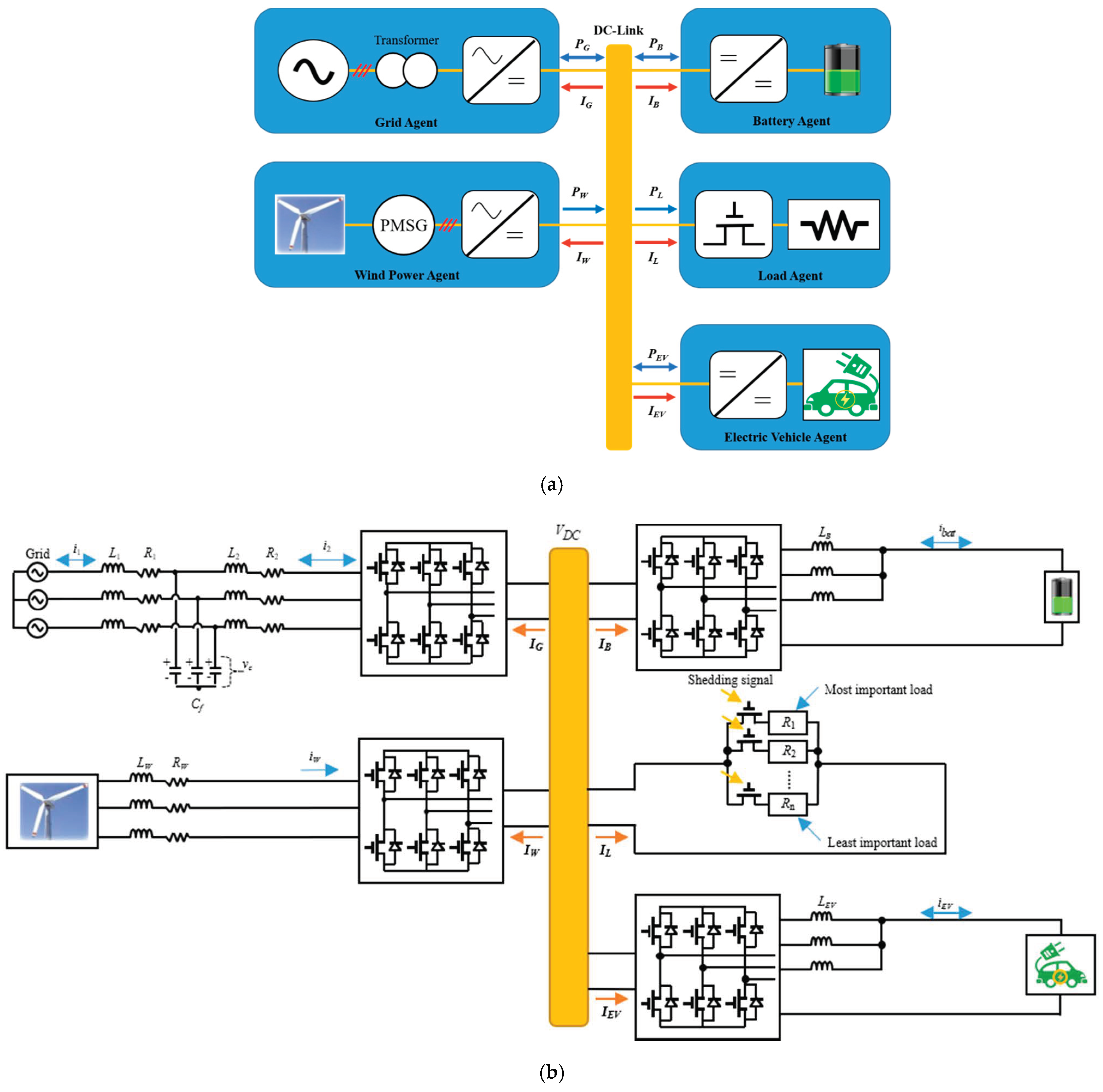
Figure 1. Configuration of EV-connected DCMG. (a) Simplified configuration of EV-connected DCMG; (b) detailed configuration of EV-connected DCMG.
Figure 1b shows a detailed configuration of the DCMG system with EV and grid connections. The grid-connected inverter uses an inductive-capacitive-inductive (LCL) filter to reduce the switching harmonics in the grid-side currents in the grid agent. The filter resistances, filter inductances, and filter capacitance are denoted by R1, R2, L1, L2, and Cf, respectively. In addition, i1 and i2 represent the grid-side current and inverter-side current, respectively. In the grid-connected mode of the DCMG, the grid agent operates with three operating modes. When the grid agent supplies the power from the main grid into the DCMG system to support the DC-link voltage, the grid agent operates in the DC-link voltage control converter (VDC CON) mode. The grid agent also works in the inverter mode (VDC INV), in which the grid agent regulates the DC-link voltage by injecting the surplus power from the DCMG system into the main grid. The remaining operation of the grid agent is the IDLE mode in which the grid agent and DCMG system are interconnected without any power exchange.
Two bidirectional interleaved buck-boost DC-DC converters are installed to connect the DCMG system with the battery agent and the EV agent through an inductive (L) filter. The battery and EV agents have five operating modes: two voltage control modes, two current control modes, and the IDLE mode. The DC-link voltage control by discharging (VDC D) mode is the first one, in which the battery and EV agents control the DC-link voltage by supplying the discharging power into the DC-link. On the contrary, the agent operating mode is the DC-link voltage control by charging (VDC C) mode, if the DC-link voltage is maintained by charging the battery or EV agent with the surplus power. Two current control modes are charging with the maximum allowable power (Max C) and discharging with the maximum allowable power (Max D). The last operating mode of the battery and EV agents is the IDLE mode in which the power does not exchange between these agents and the DC-link. In Figure 1b, LB and LEV represent the filter inductances of the battery and EV agents, respectively, and ibat and iEV denote the battery and EV currents, respectively.
An L filter is also employed in the wind power agent to connect the PMSG and unidirectional AC-DC converter. In Figure 1b, LW and RW are the filter inductance and resistance parameters, while iW denotes the phase current of the PMSG. There are two operating modes in the wind power agent. The first operating mode is the maximum power point tracking (MPPT) mode, in which the wind power agent maximally extracts power from the wind turbine. The next operating mode is the DC-link voltage control (VDC) mode. This mode occurs in the condition that the generated power from the wind power agent PW is greater than the demand load power PL, and any other agents cannot absorb the surplus power of the DCMG system. In this situation, the nominal DC-link voltage should be maintained by reducing PW.
Whenever the load power is higher than the available power in DCMG, the load agent commences load shedding (SHD) mode to prevent the DCMG system from collapsing by eliminating the unnecessary load. In this operation, the least important loads are first disconnected until the power balance in the system is guaranteed. When the grid is reconnected to the DCMG or the battery/EV agents have sufficient SOC level, shedded loads are reconnected by the load reconnection (RECON) algorithm. Table 1 shows the summary of the operating modes of each power agent for the EV-connected DCMG. To ensure a DCMG operation, the reliable control of power electronics converters is an indispensable part. To effectively realize all the operating modes by each power agent in Table 1, power converter controllers are implemented by modifying the configuration in [8].
Table 1. Operating modes of power agents for EV-connected DCMG.
| Power Agent | Operating Modes | Abbreviation |
|---|---|---|
| Grid agent | Idle | IDLE |
| DC-link voltage control by converter operation | VDC CON | |
| DC-link voltage control by inverter operation | VDC INV | |
| Battery agent | Idle | IDLE |
| DC-link voltage control by charging | VDC C | |
| DC-link voltage control by discharging | VDC D | |
| Charging with maximum allowable power | Max C | |
| Discharging with maximum allowable power | Max D | |
| EV agent | Idle | IDLE |
| DC-link voltage control by charging | VDC C | |
| DC-link voltage control by discharging | VDC D | |
| Charging with maximum allowable power | Max C | |
| Discharging with maximum allowable power | Max D | |
| Wind power agent | Maximum power point tracking | MPPT |
| DC-link voltage control | VDC | |
| Load agent | Load shedding | SHD |
| Load reconnection | RECON |
References
- Hu, J.; Shan, Y.; Guerrero, J.M.; Ioinovici, A.; Chan, K.W.; Rodriguez, J. Model Predictive Control of Microgrids—An Overview. Renew. Sustain. Energy Rev. 2021, 136, 110422.
- Zou, S.; Ma, Z.; Yang, N. Decentralised Hierarchical Coordination of Electric Vehicles in Multi-microgrid Systems. IET Gener. Transm. Distrib. 2019, 13, 2899–2906.
- Dai, Y.; Gao, Y.; Gao, H.; Zhu, H. Real-time Pricing Scheme Based on Stackelberg Game in Smart Grid with Multiple Power Retailers. Neurocomputing 2017, 260, 149–156.
- Zhou, B.; Yang, R.; Li, C.; Cao, Y.; Wang, Q. Multiobjective Model of Time-of-Use and Stepwise Power Tariff for Residential Consumer in Regulated Power Markets. IEEE Syst. J. 2018, 12, 2676–2687.
- Shin, H.; Baldick, R. Plug-in Electric Vehicle to Home (V2H) Operation under a Grid Outage. IEEE Trans. Smart Grid 2017, 8, 2032–2041.
- Nguyen, T.V.; Kim, K.H. An Improved Power Management Strategy for MAS-Based Distributed Control of DC Microgrid under Communication Network Problems. Sustainability 2020, 12, 122.
- Mehdi, M.; Kim, C.; Saad, M. Robust Centralized Control for DC Islanded Microgrid Considering Communication Network Delay. IEEE Access 2020, 8, 77765–77778.
- Padhilah, F.A.; Kim, K.H. A Power Flow Control Strategy for Hybrid Control Architecture of DC Microgrid under Unreliable Grid Connection Considering Electricity Price Constraint. Sustainability 2020, 12, 7628.
- Wu, X.; Hu, X.; Yin, X.; Zhang, C.; Qian, S. Optimal Battery Sizing of Smart Home via Convex Programming. Energy 2017, 45, 444–453.
- Zhou, L.; Zhang, Y.; Lin, X.; Li, C.; Cai, Z.; Yang, P. Optimal Sizing of PV and BESS for a Smart Household Considering Different Price Mechanisms. IEEE Access 2018, 6, 41050–41059.
- Mohsenian-Rad, A.; Wong, V.W.S.; Jatskevich, J.; Schober, R.; Leon-Garcia, A. Autonomous Demand-side Management Based on Game-theoretic Energy Consumption Scheduling for the Future Smart Grid. IEEE Trans. Smart Grid 2010, 1, 320–331.
- Daim, T.U.; Wang, X.; Cowan, K.; Shott, T. Technology Roadmap for Smart Electric Vehicle-to-grid (V2G) of Residential Chargers. J. Innov. Entrep. 2016, 5, 15.
- Hua, L.; Wang, J.; Zhou, C. Adaptive Electric Vehicle Charging Coordination on Distribution Network. IEEE Trans. Smart Grid 2014, 5, 2666–2675.
- Daryabari, M.K.; Keypur, R.; Golmohamadi, H. Robust Self-scheduling of Parking Lot Microgrids Leveraging Responsive Electric Vehicles. Appl. Energy 2021, 290, 116802.
- Guo, Y.; Xiong, J.; Xu, S.; Su, W. Two-Stage Economic Operation of Microgrid-Like Electric Vehicle Parking Deck. IEEE Trans. Smart Grid 2016, 7, 1703–1712.
- Li, Y.; Han, M.; Yang, Z.; Li, G. Coordinating Flexible Demand Response and Renewable Uncertainties for Scheduling of Community Integrated Energy Systems with an Electric Vehicle Charging Station: A Bi-level Approach. IEEE Trans. Sustain. Energy 2021.
- Pahasa, J.; Ngamroo, I. PHEVs Bidirectional Charging/Discharging and SoC control for Microgrid Frequency Stabilization Using Multiple MPC. IEEE Trans. Smart Grid 2015, 6, 526–533.
- Habib, H.U.R.; Subramaniam, U.; Waqar, A.; Farhan, B.S.; Kotb, K.M.; Wang, S. Energy Cost Optimization of Hybrid Renewables Based V2G Microgrid Considering Multi Objective Function by Using Artificial Bee Colony Optimization. IEEE Access 2020, 8, 62076–62093.
- Noel, L.; De Rubens, G.Z.; Kester, J.; Sovacool, B.K. Beyond Emissions and Economics: Rethinking the Co-benefits of Electric Vehicles (EVs) and Vehicle-to-grid (V2G). Transp. Policy 2018, 71, 130–137.
More
Information
Subjects:
Engineering, Electrical & Electronic
Contributor
MDPI registered users' name will be linked to their SciProfiles pages. To register with us, please refer to https://encyclopedia.pub/register
:
View Times:
982
Revision:
1 time
(View History)
Update Date:
10 Aug 2021
Table of Contents


Notice
You are not a member of the advisory board for this topic. If you want to update advisory board member profile, please contact office@encyclopedia.pub.
OK
Confirm
Only members of the Encyclopedia advisory board for this topic are allowed to note entries. Would you like to become an advisory board member of the Encyclopedia?
Yes
No
${ textCharacter }/${ maxCharacter }
Submit
Cancel
Back
Comments
${ item }
|
${ item.createdUser.fullName }
${ item.createdAt }
${ item.vote }
${ item.reply }
Delete
${ reply.createdUser.fullName }
${ reply.createdAt }
${ reply.vote }
Delete
There is no reply to this comment~
${ item.replyTextCharacter }/${ item.replyMaxCharacter }
Submit
Cancel
More
No more~
There is no comment~
${ textCharacter }/${ maxCharacter }
Submit
Cancel
${ selectedItem.replyTextCharacter }/${ selectedItem.replyMaxCharacter }
Submit
Cancel
Confirm
Are you sure to Delete?
Yes
No