 +1 credit
| Version | Summary | Created by | Modification | Content Size | Created at | Operation |
|---|---|---|---|---|---|---|
| 1 | Trunal Dhawale | + 4374 word(s) | 4374 | 2020-07-07 09:39:52 | | | |
| 2 | Rita Xu | -1614 word(s) | 2760 | 2020-07-10 05:47:41 | | | | |
| 3 | Trunal Dhawale | Meta information modification | 2760 | 2020-07-14 10:55:43 | | |
Video Upload Options
The existing experimental tests are mainly designed to study the mechanical response of materials at various strain rates. Many researchers performed the experimental test in tension, compression, and shear (with torsion test) over a wide range of strain rates. They found out that material exhibits an increase in yield stress as well as flows stress with an increase in strain rate. It illustrates that there is a need for experimental data to study the material behaviour over the full range of strain rates, from quasi-static to high strain rate test. Many special techniques have been developed to bridge the strain rate gap between quasi-static and high strain rate testing to provide a method for an intermediate strain rate test for engineering materials. Some researchers have tried to conduct intermediate strain rate tests with standard servo-hydraulic load frames. However, the results of such tests are not accurate. The problem is that during the experiment, the whole machine is not in static equilibrium. The inertial effect influences the experimental data. The records obtained from these machines are often noisy with large oscillation. therefore, the comprehensive review is given to describes the development and evolution of the existing intermediate strain rate testing devices which includes the working principles, some critical theories, technological innovation in load measurement techniques, components of the device, basic technical assumption, and measuring techniques. In addition, some research direction on future implementation and development of an intermediate strain rate apparatus is also discussed in detail.
1. Definition
Materials undergo various loading conditions during different manufacturing processes, including varying strain rates and temperatures. Research has shown that the deformation of metals and alloys during manufacturing processes such as metal forming, machining, and friction stir welding (FSW), can reach a strain rate ranging from 10−1 to 106 s−1. Hence, studying the flow behavior of materials at different strain rates is important to understanding the material response during manufacturing processes. Experimental data for a low strain rate of <101 s−1 and a high strain rate of >103 s−1 are readily available by using traditional testing devices such as a servo-hydraulic testing machine and the split Hopkinson pressure bar method, respectively. However, for the intermediate strain rate (101 to 103 s−1), very few testing devices are available. Testing the intermediate strain rate requires a demanding test regime, in which researchers have expanded the use of special instruments.
2. Introduction
Studying the mechanical behavior of materials in manufacturing processes at different strain rates and temperatures is very important for researchers to develop predictive material behavior models. An overview of typical strains, strain rates, and temperatures found in manufacturing processes is given in Table 1. The table reveals that in commonly used manufacturing techniques, such as machining, forging, forming, and friction stir welding (FSW) [1][2][3], the materials are deformed differently under different conditions. In addition, the microstructure of the material is significantly affected by the thermomechanical constraints and is difficult to access experimentally. For example, during manufacturing processes, the strain rates are in the order of 10−1 to 106 s−1, while the those obtained in conventional testing machines are in the order of 10−3 to 101 s−1. Hence, the predictability of any material model largely depends on the accuracy of the material parameters obtained for the constitutive model from experimental tests [4].
Table 1. Typical strains, strain rates, and temperature ratio (T/Tm) of some manufacturing processes also given by [5]. (T = Temperature during the process, Tm = melting temperature of the material).
| Manufacturing Process | Strain | Strain Rate (s−1) | T/Tm |
|---|---|---|---|
| Extrusion | 2 to 5 | 10−1 to102 | 0.16–0.7 |
| Metal Forging | 0.1 to 0.5 | 100 to 103 | 0.16–0.7 |
| Machining | 1 to 10 | 103 to 106 | 0.16–0.9 |
| Sheet metal forming | 0.1 to 0.5 | 100 to 102 | 0.16–0.7 |
| Friction Stir Welding (FSW) | 0.1 to 5 | ≤102 | 0.16–0.9 |
Many different testing devices have been developed over the years, depending on the type of material and the property to be determined, some of which have become standards in industrial practice. The experimental procedure usually consists of submitting a specimen to different loading conditions and measuring the applied force and specimen deformation. Some examples of this type of experiment are tensile, compression, shear, punch, and bulge tests. When the material behavior is more complex, and several parameters (e.g., strain rate, temperature, and strain) must be identified for material modelling, the characterization becomes more difficult, and multiple tests have to be used.
Many researchers have carried out the experimental tests at various strain rate conditions and found that the material exhibits an increased yield strength and flow stress with increased strain rate [6][7][8][9][10][11][12], the existing material models developed by the researchers cannot predict, very accurately, the microstructure changes that are taking place during the manufacturing processes [13][14]. During heat deformation, the material undergoes dynamic strain-hardening and dynamic softening (consisting of dynamic recovery (DRV) and dynamic recrystallization (DRX)), resulting in the evolution of the complex microstructure of the deformed material which is directly reflected in the flow stress curves [15]. At the beginning of straining, there is an increase in the work hardening due to dislocation generation and accumulation. As the deformation continues, part of the stored energy is released with the dislocation annihilation, in which the microstructure and the properties of the material can be partially restored to their original values, called dynamic recovery. Further increase of strain leads to the formation of the new grains called dynamic recrystallization. This behavior of the material is greatly affected by the temperature and strain rate. The higher the temperature of deformation and the lower the strain rate, the larger the sub grains that are formed during high-temperature deformation. As they increase in size, the sub grains contain fewer dislocations and enters a steady-state given by the dynamic equilibrium of storage and recovery of defects. It means the material experiences a lesser strain hardening effect. At low strain rate domain (i.e., <0.1 s−1), DRX is mainly governed by the higher growth of DRX grains due to longer (deformation) time available for the grain boundary migration. As a result, a larger DRX grain size is obtained. At high strain rate domain (i.e., >1 s−1), DRX is mainly governed by the higher nucleation due to combining effects of higher stored energy, adiabatic heating, and limited (deformation) time for grain boundary migration. As a result, finer grain size is obtained. Hence it is important to study the behavior of material at different strain rates. The complete overview on the effect of the strain rate on the microstructure behavior of the material is given by the McQueen [16]. A complete description of all of these phenomena in a single constitutive model is an extremely difficult task. Thus, more experimental tests are required with different engineering parameters and test environments to study the behavior of materials over the wide range of strain rates, from quasi-static to high.
The existing commercial and traditional testing devices are mainly divided based on the speed of loading (or at various strain rates) from low to high. Table 2 provides a representation of the range of applicable strain rates covered by existing test machines, including types of loading, such as tension, compression, and shear.
Table 2. Characterization of the machines based on the strain rate and type of loading.
| Testing Technique | Applied Strain Rate (s−1) | ||
|---|---|---|---|
| Low Strain Rate (≤101) | Intermediate Strain Rate (101–103) | High Strain Rate (>103) | |
| Compression Tests | Conventional load frame and servo-hydraulic machine | Commercial machines like MTS, Shimadzu, Instron, etc., Special Servo hydraulic load frames, drop tower, Flywheel device | Split Hopkinson pressure bar, Gas gun, Taylor impact test |
| Tensile Tests | Split Hopkinson bar in tension, Flyer plate, expanding ring | ||
| Shear tests | Conventional shear test, special servo-hydraulic frames, Torsion test | - | Compressive/tensile shear apparatus, Hopkinson Klosky bar in torsion |
Among the three strain rate divisions in Table 2, conventional load frame and standard servo-hydraulic testing machines [17][18][19][20] are generally used for quasi-static strain rates in the range of ≤101 s−1 with different load conditions. These tests are called quasi-static because the specimen and the test machine are in static equilibrium during the test. For high strain rate testing >103 s−1, the split Hopkinson pressure bar (SHPB) method [21][22] is often used. In the last decade, many proven experimental techniques have been developed for high strain rate testing, e.g., compression loading, drop weight [23], SHPB [24], and gas guns [25] are regularly used. For tensile loading, the split Hopkinson tension bar (SHTB) [26][27][28], flyer plate impact test [29], and the expansion ring [30] are used. For torsion experiments, the torsional split Hopkinson bar (TSHB) with different loading mechanisms such as pre-stored energy loading [31], explosive loading [32], direct impact loading [33], and electromagnetic loading [34] are generally used. However, tests at an intermediate strain rate in the range of 101 to 103 s−1 are not very common, and neither servo-hydraulic machines nor SHB techniques are suitable for testing with an intermediate strain rate regime.
Numerous methods have been introduced to bridge the gap between quasi-static and high strain rate testing in order to provide experimental data for engineering materials. Servo-hydraulic machines were considered as a solution to perform tests with an intermediate strain rate regime. The results of such tests, however, are not very accurate. The problem is that during the experiment, stress–strain data are influenced by the effect of high inertia, and records obtained from such machines are often noisy with large oscillations. As a result, servo-hydraulic machines only give reliable measurements at strain rates below 10 s−1.
After the development of the split Hopkinson bar technique [22] in 1949, a few researchers tried to modify classical dynamic split Hopkinson pressure bar device to achieve a deformation rate in the intermediate rate regime by increasing the loading time [35]. However, the main drawback of the modified device is that the duration of the test is limited to the length of the bars [36]. Such a duration does not allow the significant strain to be accumulated in the specimen at medium strain rates. Therefore, an alternative loading technique is required. Over the last decade, some researchers have developed specialized test machines capable of performing intermediate strain rate tests to study material characterization, such as special commercial machines designed by Instron, Shimadzu, etc. [37][38]; elastic-bar-type systems (ISO 26203-1: 2018) [39], modified servo-hydraulic load frames (ISO 26203-2:2011) [40], hybrid testing apparatus [41], drop tower [42], flywheel device [43], and flywheel wedge [44].
The material response at intermediate strain rates is of great interest to the automotive industry and producers of electronic packaging [45][46]. Additionally, intermediate strain rates have been recognized as being important in the transitioning of material response and changing of the material deformation mechanism from low to high strain rates [47][48]. Therefore, in the past decade, the material response at intermediate strain rates has attracted more attention. In addition, material properties at intermediate strain rates are rarely characterized due to experimental difficulties, leaving a significant gap in the experimental data between low and high strain rates for high-fidelity strain rate dependent material model development. Therefore, a comprehensive review is required for research leading to a better understanding of the intermediate strain rate test device.
3. Data, Model, Applications and Influences
Over the past decade, the experts from various industries such as Instron, MTS, Shimadzu, and Zwick/Roell have developed a new family of high-speed servo hydraulic testing machines specifically designed to cope with the dynamics of intermediate strain rate testing [37][38][49][50], and after these devices are used in a number of applications to predict material behavior, for instance; in the landing gear on aircraft or the crash impact of a road vehicle, all of these examples involve one or more components of a product that are subjected to intermediate strain rate impact <103 s−1. The existing test devices combine the load capacities of a servo-hydraulic actuator, a drop tower, and a flywheel machine in conjunction with a load measurement technique, such as the piezoelectric load cell and Hopkinson bar technique.
High-speed servo hydraulic machines are used for all kinds of impact loadings like dynamic tension, compression, bending, and shear loading. The most important high-speed test mode is the tension test. For example, Figure 1 shows the schematic diagram of the high-speed testing machine [51]. The stroke speed is controlled by the opening and closing of the servo-valve of hydraulic supply. The test machine can deliver a speed range from 1 mm/s to 20 m/s.
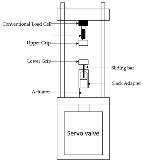
Figure 1. Schematic diagram of the high-speed testing machine.
The strain rate data obtained from this machine is from quasi-static to intermediate strain rates. Dynamic load is introduced to the lower grip through a slack adaptor that consists of a hollow tube and a sliding bar with a conical tip. When the machine is actuated, the hollow tube travels freely with the actuator over a distance to reach a specified velocity before making contact with the cone-shaped end of the sliding bar that is connected to the lower grip. The slack adaptor eliminates the inertia effect of the lower grip and actuator in its acceleration stage. However, the sudden engagement with the upper portion of the setup generates a high amplitude stress wave, causing oscillations at the system’s natural frequency, i.e., system ringing [52]. A conventional piezoelectric load cell installed in the machine shows the vibration and oscillating signals. See Figure 1. At strain rates above 50 s−1 these systems become unreasonably difficult to acquire load data. Therefore, experimentalists are forced to use smoothing or filtering the load test data by using low-pass filters, averaging or other algorithms (e.g., power-law function) [53][54], or the single degree of freedom (SDOF) model (spring mass damping model) [51]. However, the accuracy of such filtering procedures, to a great extent, depends on the user’s choice of the filtering algorithm. It also includes a risk of losing some important characteristics with respect to the hardening behavior of the tested material.
In 1996, LeBlanc et al. [41] designed and introduced a unique hybrid testing apparatus to perform intermediate strain rate tests in order to improve the load measuring data that observed in the high-speed servo hydraulic machines. This device was developed by combining a servo-hydraulic machine with the split Hopkinson bar technique. The apparatus combines the loading capabilities of a servo-hydraulic testing machine and the load measuring technique of a Hopkinson bar [55]. The bar is freely suspended against the specimen. When the specimen is compressed or elongated against the bar, the loading of the specimen is transmitted to the bar at the elastic wave velocity. The load in the bar is determined from strain gauges located close to the loading end; the measurement is free of disturbance until the reflected wave reaches the gage and interferes with the loading wave. The stress in the test specimen is assumed to be uniaxial and can be calculated using the elastic wave analysis of the Hopkinson bar.
Hence it is concluded that the piezoelectric load cell shows the greatest vibration and oscillation of the load data compared to the Hopkinson bar technique due to high inertial effect during impact loading. However, the test time obtained by these devices is very short, which is insufficient to deform the specimen to a relatively large strain at intermediate strain rates. Moreover, it is difficult to perform the test at different strain rate regimes due to restriction in the load cell capacity and bar length. For this reason, some researchers have tried to improve the existing intermediate strain rate test device to obtain a longer test duration and good quality measurement data by modifying the bar system [56][57] and improving the load measurement technique (Wave separation method) [58][59]. In addition, there is not enough work done on high-temperature experimental testing. The development of a temperature experiment allowed researchers to study the combined effects of strain rate and temperature on the mechanical and microstructural behavior of materials. Hence, an intermediate strain rate device must be equipped with heating device to study the behavior of the material over a wide range of temperature. The existing test devices focus only on the tensile and compressive behavior of the material. There is no intermediate strain rate testing device available to study the pure shear behavior. The shear test can reproduce the same response of the material behaviors encountered in processes such as machining, friction stir welding, and cutting. Also, the development of combined loading techniques, such as shear-tensile and shear-compression, for an intermediate strain rate device, can also be very useful for material modelling, numerical simulation, engineering design, etc. The combined loading technique will help to understand the behavior of the material in complex stress states. Therefore, there is an increasing need to develop reliable techniques to study the characteristics of materials at several experimental conditions including temperature, shear loading at intermediate strain rates and to provide experimental data to improve the material model.
References
- Kalpakjian, S. Manufacturing Processes for Engineering Materials, 3rd ed.; Addison-Wesley/Longman: Menlo Park, NJ, USA, 1997.
- Jomaa, W.; Mechri, O.; Levesque, J.; Songmene, V.; Bocher, P.; Gakwaya, A. Finite element simulation and analysis of serrated chip formation during high–speed machining of AA7075–T651 alloy. J. Manuf. Process. 2017, 26, 446–458.
- Chen, Z.W.; Cui, S. Strain and strain rate during friction stir welding/processing of Al-7Si-0.3Mg alloy. IOP Conf. Ser. Mater. Sci. Eng. 2009, 4, 012026.
- Guo, Y. An integral method to determine the mechanical behavior of materials in metal cutting. J. Mater. Process. Technol. 2003, 142, 72–81.
- Jaspers, S.P.F.C.; Dautzenberg, J.H. Material behaviour in metal cutting: Strains, strain rates and temperatures in chip formation. J. Mater. Process. Technol. 2002, 121, 123–135.
- Chalivendra, V.; Song, B.; Casem, D. Dynamic Behavior of Materials, Volume 1; Springer: New York, NY, USA, 2013.
- Srivatsan, T.S.; Hoff, T.; Sriram, S.; Prakash, A. The effect of strain rate on flow stress, strength and ductility of an Al-Li-Mg alloy. J. Mater. Sci. Lett. 1990, 9, 297–300.
- Yoshino, M.; Shirakashi, T. Flow-stress equation including effects of strain-rate and temperature history. Int. J. Mech. Sci. 1997, 39, 1345–1362.
- Yamada, H.; Kami, T.; Mori, R.; Kudo, T.; Okada, M. Strain rate dependence of material strength in aa5xxx series aluminum alloys and evaluation of their constitutive equation. Metals 2018, 8, 576.
- Zaretsky, E.B.; Kanel, G.I. Effect of temperature, strain, and strain rate on the flow stress of aluminum under shock-wave compression. J. Appl. Phys. 2012, 112, 1–9.
- Senkov, O.N.; Jonas, J.J. Effect of strain rate and temperature on the flow stress of β-phase titanium-hydrogen alloys. Metall. Mater. Trans. A Phys. Metall. Mater. Sci. 1996, 27, 1303–1312.
- Frost, H.J.; Ashby, M.F. Deformation-mechanism Maps: The Plasticity and Creep of Metals and Ceramic; Elsevier Science Limited: Grand Rapids, MI, USA, 1982.
- Lindgren, L.E.; Domkin, K.; Hansson, S. Dislocations, vacancies and solute diffusion in physical based plasticity model for AISI 316L. Mech. Mater. 2008, 40, 907–919.
- Liu, J.; Edberg, J.; Tan, M.J.; Lindgren, L.E.; Castagne, S.; Jarfors, A.E. Finite element modelling of superplastic-like forming using a dislocation density-based model for AA5083. Model. Simul. Mater. Sci. Eng. 2013, 21, 025006.
- Zhang, H.; Zhang, K.; Zhou, H.; Lu, Z.; Zhao, C.; Yang, X. Effect of strain rate on microstructure evolution of a nickel-based superalloy during hot deformation. Mater. Des. 2015, 80, 51–62.
- McQueen, H.J.; Jonas, J.J. Recovery and Recrystallization during High Temperature Deformation, Vol. 6; Academic Press, Inc.: Montreal, QC, Canada, 1975.
- Huh, H.; Ahn, K.; Lim, J.H.; Kim, H.W.; Park, L.J. Evaluation of dynamic hardening models for BCC, FCC, and HCP metals at a wide range of strain rates. J. Mater. Process. Technol. 2014, 214, 1326–1340.
- Zhu, J.; Xia, Y.; Gu, G.; Zhou, Q. Extension of Non-Associated Hill48 Model for Characterizing Dynamic Mechanical Behavior of a Typical High-Strength Steel Sheet. In Proceedings of the ASME 2014 International Mechanical Engineering Congress and Exposition IMECE2014, Montreal, QC, Canada, 14–20 November 2014.
- Xiao, X. Dynamic tensile testing of plastic materials. Polym. Test. 2008, 27, 164–178.
- Dodd, B.; Bai, Y. Adiabatic Shear Localization Frontiers and Advances, 2nd ed.; Elsevier: London, UK, 2012.
- Hopkinson, B. A method of measuring the pressure produced in the detonation of high, explosives or by the impact of bullets. Philos. Trans. R. Soc. Lond. Ser. A Contain. Pap. Math. Phys. Character 1914, 213, 437–456.
- Kolsky, H. An Investigation of the Mechanical Properties of Materials at very High Rates of Loading. Proc. Phys. Soc. Sect. B 1949, 62, 676.
- Taheri-Behrooz, F.; Shokrieh, M.M.; Abdolvand, H.R. Designing and manufacturing of a drop weight impact test machine. Eng. Solid Mech. 2013, 1, 69–76.
- Song, B.; Weinong, C. Split Hopkinson pressure bar techniques for characterizing soft materials. J. Solids Struct. 2005, 2, 113–152.
- Zhang, T. Progress and application of combined compression and shear wave loading technique. Adv. Mech. 2007, 37, 398–408.
- Rogers, W.P.; Nemat-Nasser, S. Transformation Plasticity at High Strain Rate in Magnesia-Partially-Stabilized Zirconia. J. Am.Ceram Soc. 1990, 73, 136–139.
- Staab, G.H.; Gilat, A. A Direct-tension Split Hopkinson Bar for High Strain-rate Testing. Exp. Mech. 1991, 31, 232–235.
- Niordson, F. A Unit for Testing Materials at High Strain Rates. Exp. Mech. 1965, 5, 29–32.
- Gebbeken, N.; Greulic, S.; Pietzsch, A. Hugoniot properties for concrete determined by full-scale detonation experiments and flyer-plate-impact tests. Int. J. Impact Eng. 2006, 32, 2017–2031.
- Hoggatt, C.R.; Recht, R.F. Stress-strain data obtained at high rates using an expanding ring. Exp. Mech. 1969, 9, 441–448.
- Baker, W.E.; Yew, C. Strain-rate effects in the propagation of torsional plastic waves. J. Appl. Mech. 1966, 33, 917.
- Duffy, J.; Campbell, J.; Hawley, R. On the Use of a Torsional Split Hopkinson Bar to Study Rate Effects in 1100-0 Aluminum. J. Appl. Mech. 1971, 38, 83–91.
- Nie, X.; Prabhu, R.; Chen, W.W.; Caruthers, J.M.; Weerasooriya, T. A Kolsky Torsion Bar Technique for Characterization of Dynamic Shear Response of Soft Materials. Exp. Mech. 2011, 51, 1527–1534.
- Yu, X.; Chen, L.; Fang, Q.; Jiang, X.; Zhou, Y. An Electromagnetic driven Torsional Split Hopkinson Bar. In Proceedings of the ICILSM 2018, Xi’an, China, 7–11 May 2018.
- Cloete, T.J.; Paul, G.; Ismail, E.B. Hopkinson bar techniques for the intermediate strain rate testing of bovine cortical bone. Philos. Trans. R. Soc. A Math. Phys. Eng. Sci. 2014, 372, 20130210.
- Song, B.; Syn, C.; Grupido, C.; Chen, W.; Lu, W.Y. A Long Split Hopkinson Pressure Bar (LSHPB). Exp. Mech. 2008, 48, 809–815.
- Instron. High Strain Rate VHS System. Data Sheet. 2016, pp. 1–4. Available online: https://www.instron.us/-/media/literature-library/products/2019/05/vhs-high-strain-rate-system-pod.pdf?la=en (accessed on 13 June 2019).
- Shimadzu. Impact Testing. Available online: https://www.shimadzu.com/an/pdf/388_c225e037a.pdf (accessed on 1 November 2017).
- ISO 26203-1:2018. Metallic Materials—Tensile Testing at High Strain Rates—Part 1: Elastic-Bar-Type Systems. Available online: https://www.iso.org/standard/72573.html (accessed on 1 February 2010).
- ISO 26203-2:2011. Metallic Materials—Tensile Testing at High Strain Rates—Part 2: Servo-Hydraulic and Other Test Systems. Available online: https://www.iso.org/standard/46275.html (accessed on 1 October 2011).
- Leblanc, M.M.; Lassila, D.H. A hybrid technique for compression testing at intermediate strain rates. Exp. Tech. 1996, 20, 21–24.
- Song, B.; Sanborn, B.; Heister, J.; Everett, R.; Martinez, T.; Groves, G.; Johnson, E.; Kenney, D.; Knight, M.; Spletzer, M. Development of “dropkinson” Bar for Intermediate Strain-rate Testing. EPJ Web Conf. 2018, 183, 02004.
- Froustey, C.; Lambert, M.; Charles, J.L.; Lataillade, J.L. Design of an impact loading machine based on a flywheel device: Application to the fatigue resistance of the high rate pre-straining sensitivity of aluminium alloys. Exp. Mech. 2007, 47, 709–721.
- Sturges, J.L.; Coler, B.N. The flying wedge: A method for high-strain-rate tensile testing. Part 2. Reasons for its development and general description. Int. J. Impact Eng. 2003, 28, 891–908.
- Paul, S.K.; Raj, A.; Biswas, P.; Manikandan, G.; Verma, R.K. Tensile flow behavior of ultra low carbon, low carbon and micro alloyed steel sheets for auto application under low to intermediate strain rate. Mater. Des. 2014, 57, 211–217.
- Jing, J.; Gao, F.; Johnson, J.; Liang, F.Z.; Williams, R.L.; Qu, J. Brittle versus ductile failure of a lead-free single solder joint specimen under intermediate strain rate. IEEE Trans. Compon. Packag. Manuf. Technol. 2011, 1, 1456–1464.
- Mandal, S.; Jayalakshmi, M.; Bhaduri, A.K.; Sarma, V.S. Effect of Strain Rate on the Dynamic Recrystallization Behavior in a Nitrogen-Enhanced 316L(N). Metall. Mater. Trans. A Phys. Metall. Mater. Sci. 2014, 45, 5645–5656.
- Liu, Z.Y.; Huang, T.T.; Liu, W.J.; Kang, S. Dislocation mechanism for dynamic recrystallization in twin-roll casting Mg-5.51Zn-0.49Zr magnesium alloy during hot compression at different strain rates. Trans. Nonferrous Metals Soc. China 2016, 26, 378–389.
- Zwick/Roell Materials Testing. Available online: https://www.zwickroell.com/en/servohydraulic-testing-machines/high-speed-testing-machine (accessed on 1 November 2008).
- Bardenheier, R.; Rogers, G. Dynamic impact testing with servohydraulic testing machines. J. Phys. IV 2006, 134, 693–699.
- Zhu, D.; Rajan, S.D.; Mobasher, B.; Peled, A.; Mignolet, M. Modal Analysis of a Servo-Hydraulic High Speed Machine and its Application to Dynamic Tensile Testing at an Intermediate Strain Rate. Exp. Mech. 2011, 51, 1347–1363.
- Sahraoui, S.; Lataillade, J.L. Analysis of load oscillations in instrumented impact testing. Eng. Fract. Mech. 1998, 60, 437–446.
- Found, M.S.; Howard, I.C.; Paran, A.P. Interpretation of signals from dropweight impact tests. Compos. Struct. 1998, 42, 353–363.
- Rusinek, A.; Cheriguene, R.; Bäumer, A.; Klepaczko, J.R.; Larour, P. Dynamic behaviour of high-strength sheet steel in dynamic tension: Experimental and numerical analyses. J. Strain Anal. Eng. Des. 2008, 43, 37–53.
- Othman, R.; Guégan, P.; Challita, G.; Pasco, F.; LeBreton, D. A modified servo-hydraulic machine for testing at intermediate strain rates. Int. J. Impact Eng. 2009, 36, 460–467.
- Gilat, A.; Matrka, T.A. A new compression intermediate strain rate testing apparatus. EPJ Web Conf. 2010, 6.
- Whittington, W.R.; Oppedal, A.L.; Francis, D.K.; Horstemeyer, M.F. A novel intermediate strain rate testing device: The serpentine transmitted bar. Int. J. Impact Eng. 2015, 81, 1–7.
- Othman, R. The Kolsky-Hopkinson bar machine: Selected topics. In The Kolsky-Hopkinson Bar Machine; Springer International Publishing: Jeddah, Saudi Arabia, 2018; pp. 1–282.
- Othman, R. Wave separation techniques. In The Kolsky-Hopkinson Bar Machine: Selected Topics; Springer International Publishing: Cham, Switzerland, 2018; pp. 183–203.

