| Version | Summary | Created by | Modification | Content Size | Created at | Operation |
|---|---|---|---|---|---|---|
| 1 | Marcelo A. Perez | + 6022 word(s) | 6022 | 2021-03-04 10:10:53 | | | |
| 2 | Dean Liu | -3556 word(s) | 2466 | 2021-07-26 05:30:12 | | |
Video Upload Options
Distribution transformers are one of the pillars of the distribution grid. They are the interface between the medium and low-voltage grid, stepping-down the voltages to a safe and usable range for the end-users.
1. Introduction
Distribution transformers are characterized by being a highly-robust and low-cost solution, being available in different winding configurations and power ratings according to the grid requirement and mounting type [1]. Transformers have an average lifetime above 35 years under rated conditions [2].
Power quality is a term employed when referring to the power system voltage and current waveform quality at different points of the grid [3]. Low power quality phenomenons can be generated by the users, for example when consuming nonsinusoidal and unbalanced currents. Weak grids can be a source of low power quality, providing unbalanced and variable frequency voltages, among others. IEEE Std 1159-2019 and IEEE Std 519-2014 give guides on power quality measurements and recommended practice to comply and guarantee a good quality service [4][5]. Some effects of low power quality are high voltage peaks that can damage equipment, heating, losses, acoustic noise, and lifetime reduction in equipment. For utilities, low power quality is translated into additional losses on transmission lines and generators or the failure of power systems elements that can jeopardize the correct grid operation [6]. The abnormal grid operation can cause considerable economic losses to the operator and end-user. Therefore, power quality problems must not be neglected [7].
Low power quality is more pronounced in distribution systems, due to the high number of variable, nonlinear and unpredictable loads connected to them. As low voltage distribution grids are supplied by distribution transformers, these can be highly affected by the low power quality presented in these systems. When operating under these conditions, the transformer suffers higher core losses, which increase its hotspot temperature. This is a critical variable, as it relates to the winding isolation degradation and, therefore, the decrease in transformer lifetime [8].
Distribution transformers can be subject to different power quality problems in distribution grids when supplying nonlinear currents and nonlinear voltages [9][10]. Industrial applications, such as elevators, rolling mills, arc furnaces, among others, consume high amounts of current in shorts periods, worsening distribution grid operation. Power quality issues, such as flickering, can be generated due to the operation of industrial machinery [11]. Additionally, new kinds of loads establish new operating conditions for distribution transformers and the grid, for which they were not designed. For example, high penetration of wind and photovoltaic systems connected to the grid through power converters add a degree of uncertainty to the grid operation due to the high variability of these resources and also due to the harmonics injected by the power converters [12]. The distributed characteristic of these systems makes it possible that the voltage profile on the distribution grid can increase close to the connection points under high penetration periods [13]. This scenario can represent a problem for grid control systems, such as transformer tap changers, making them switch when it is not required [14]. On the other side, the widespread of electric vehicles can overload the grid. Electric vehicles fast-charging algorithms tend to delay the vehicle charging process to the night, due to economic incentives [15]. This scenario can overload the distribution transformers, reducing their lifetimes [16]. Several methods are proposed in order to reduce the impact on distribution transformers—for example, utilizing the power converter of distributed renewable energy resources for volt-var control, smart control system, intelligent and coordinated charging algorithms and including the distribution transformer hotspot model into the power converter control systems, the use of battery energy storage systems in order to operate in periods of high energy demand, among others [16][17][18].
The regulating capabilities provided by a distribution transformer are limited. To deal with slow dynamic voltage variations, they are provided with on-load taps commutating systems, which allow for modifying the winding ratio without disconnecting the load. Nonetheless, these systems operate in a discrete manner and with dynamics in the order of seconds. Additionally, they are the main transformer failure cause, which jeopardizes the distribution grid and adds additional maintenance costs. The use of electronic assisted taps commutating systems is available, allowing one to decrease the commutation times and losses. Nevertheless, they suffer additional conduction losses and operate in discrete voltage steps as well [19]. Distribution transformers do not have mechanisms to mitigate load current harmonics, it being necessary to design them to operate under these conditions. These transformers are known as k-rated transformers [20].
There are several solutions based on power electronics converter to mitigate distribution grid power quality problems. Custom Power Devices (CPDs) are power electronics-based solutions connected to the low-voltage grid that allow for mitigating for different power quality problems. Among these solutions, the Distributed Static Compensator (D-STATCOM) allows for compensating for current-based power quality problems. The Dynamic Voltage Restorer (DVR) injects a series voltage to the distribution line, which compensates for voltage disturbances. Finally, it is possible to compensate for voltage and current using a Unified Power Quality Compensator (UPQC) [6]. The effects of low power quality problems on distribution transformers, end-users, and utilities variate according to the selected solution. For example, the D-STATCOM can mitigate current harmonics generated by the load, reducing the distribution transformer stress. Nonetheless, the load can suffer from supply voltage disturbances, which can not be directly compensated by this unit. The latter is not the case for the DVR, which provides fast voltage correction. Nevertheless, harmonics currents generated by the load are not compensated by it, reducing the distribution transformer lifetime. As the UPQC combines both compensators in one single solution, it can provide sinusoidal voltages and currents to the load and distribution transformer, respectively. Its benefits on the distribution transformer depend on the connection points. For example, when the UPQC is connected to the primary-side, it can actively regulate the transformer voltage. Meanwhile, when it is connected to the secondary-side, the UPQC can provide harmonics mitigation and power factor correction, among others. Nonetheless, in both cases, one variable is not compensated. Additionally, unless storage systems are included, CPDs can not mitigate inrush currents generated by the transformer startup process or by sudden voltage variations. These systems are capable of mitigating a variety of power quality issues, but the distribution transformer is not fully protected from the unpredictable distribution grid operating conditions.
Solid-State Transformers (SSTs) are an attractive solution to cope with power quality problems, replacing conventional distribution transformers. They are based on power electronics, which allows for fast and precise voltage and current control [21]. Nonetheless, the efficiency of these systems is lower compared to other existing solutions, due to the necessity of operating with a high number of submodules, power conversion stages and the processing of the complete power flow. Compared to a distribution transformer, the complexity of an SST, the additional power electronics, and protection systems makes the SST a yet less reliable option [22]. In addition, SSTs are far more expensive compared to Low-Frequency Transformers (LFTs) of a similar power and voltage level. New power converter topologies, control systems, and redundancy are reducing this gap [23].
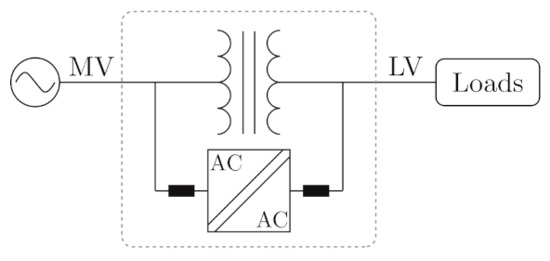
Hybrid distribution transformers (HDTs) combine a distribution transformer with one or more power electronics conversion stages, which are designed to operate at a fraction of the distribution transformer rated power. Nowadays, the available configurations, topologies, and control objectives are diverse. The HDT concept is presented in Figure 1. As can be seen, the HDT is the interface between the medium and the low-voltage grid, where the HDT is any nonspecific combination of power electronics modules with the distribution transformer [24]. Compared to other solutions, as they are based on the idea of the partial power converter, the control capabilities are limited to the power converter rating, which is typically between 10% and 20% of the transformer rated power [25]. Additionally, for the same reason, the efficiency of the power converter stages has a low impact on the overall conversion efficiency. The use of protection systems, such as bypass switches, varistors, and DC-Link clamping circuits, increases the power converter losses and volume. Nonetheless, due to the partial power converter, the protection systems have an insignificant impact on the overall efficiency and volume [26][27]. There is no restriction on the power converter location, with works reporting several different connection possibilities, i.e., medium and/or low voltage side connections, each with its own advantages and disadvantages. Therefore, the HDT configuration and power converter location will determine the power converter topology, semiconductors rating, and the provided compensation [28].

Figure 1. Hybrid distribution transformer (HDT) concept.
One of the main concerns with the applicability of new technologies in the grid is power system reliability. LFT can operate for several seconds under grid failures, such as short circuits. In contrast, power converters have a very limited short circuit current supplying capacity. Therefore, solutions based completely on semiconductors, such a SSTs, are not applicable to the actual power system yet [29]. On the other hand, some HDT configurations can operate under faults, as the HDT configuration allows for the power converter to be disconnected during the fault, letting the DT supply the short circuit currents, preserving the grid reliability [26]. We must be reminded that HDTs have attracted the attention of the industry, where ABB has filed several patents relating to their control, configurations and applications [30][31][32][33].
2. Ancillary Services Provided by Hybrid Transformers
2.1. Distribution Transformer Inrush Current Mitigation
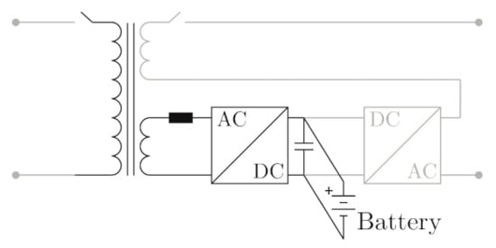
There are several methods to reduce the impact of inrush currents at the moment of the distribution transformer connection. For example, connecting the transformer phases in sequences at optimal moments. Nonetheless, it is possible to use the shunt stage of HDTs to mitigate their impact. In this scenario and based on Figure 2, using a prefluxing technique, in which the converter induces a magnetic flux equal to that induced by the grid at the connection instant, reducing the impact on the inrush currents generation. Once the transformer is connected to the grid, the power converter can be synchronized to the secondary side to initiate its normal operation, regulating the secondary side voltages and currents. When it is desired to disconnect the transformer, it is possible to use the same technique in the reverse order until the transformer flux is zero. This feature is proposed utilizing the configuration of Figure 2e along with a DC storage system connected to the DC-Link to provide the necessary energy to magnetize the transformer [34].

Figure 2. HDT configuration for inrush current mitigation.
Alternatively, the same configuration can be applied to reduce magnetizing flux DC offsets, which generate inrush currents. The mitigation is carried out by the power converter module connected to the auxiliary winding, modifying the core flux [35].
2.2. Distribution Transformer Additional Capacity
By means of a parallel connection of an SST, such as configuration of Figure 2j, and by utilizing active and reactive power control, it is possible to increase the capacity of an LFT. This scenario is represented in Figure 3. The power control is designed to supply a desired load proportion, while being able to provide power quality problem mitigation services. This solution is carried out without a considerable volume or complexity increase. Proposed solutions integrate a full rated power converter in parallel to the conventional transformer [36][37][38].

Figure 3. Increase in an LFT capacity by means of a HDT.
2.3. Hybrid Transformers to Provide Virtual Inertia
In DC-Link configuration-based HDTs, it is possible to employ DC storage systems or distributed generation systems, which can be used to provide grid frequency support. This is highly attractive in low-mechanical inertia grids, where the use of HDTs can be exploited [39]. Additionally, if multiple units are employed in a power system, they can have an important effect even in stiff grids. Figure 4 shows the DC system integration to the HDT DC-Link to provide grid frequency support.

Figure 4. HDT with virtual inertia.
By means of an external control loop, it is possible to improve the grid inertia, which allows us to soften the frequency dynamic behavior under contingencies, providing primary frequency support. The control is based on modifying the converter injected power according to the grid frequency variation, emulating the synchronous generator mechanical equation [40][41].
2.4. Renewable Energy Systems and New Kind of Loads Integration
Photovoltaic or wind generation systems can be integrated into the grid through conventional transformers. Their electromagnetic characteristic has a high impact on power quality, especially during low radiation and low wind speed periods. This operating scenario is translated into low injected active power by the renewable generating units and makes the magnetizing transformer currents considerable with respect to load currents. The generated harmonics by this phenomenon mainly depend on the winding connection type and the harmonic content presented on the grid voltage.
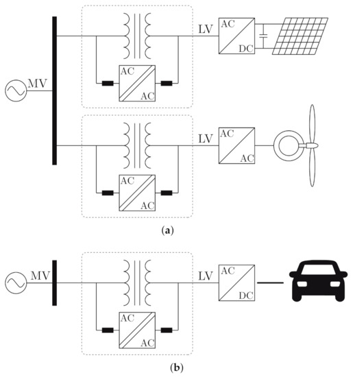
Figure 5a shows the presented scenario employing a HDT, which uses the configuration of Figure 2j. It allows for the attenuation of the renewable systems impact on the power electric system through an appropriate control system, which accounts for the transformer currents into the model. By doing this, the grid current on the medium voltage side is proportional to the current injected by the renewable generating units for all radiation and wind speed range. Additionally, it is possible to design the controllers to operate with unit power factor if the converter rated power allows it [42].

Figure 5. HDTs for the integration of renewable systems and new kind of loads. (a) Renewable systems integration. (b) Electric vehicle charging station.
New kind of loads, such as electric vehicles, can produce additional stress on distribution transformers, for instance during multiple charging processes occurring at evening and night-time, specially at the domiciliary level [16]. The use of a HDT, such as exemplified in Figure 5b, can be beneficial for the HDT lifetime, as the power converter can be used to dampen the power consumption and also avoid LFT overloading.
2.5. Decentralized Control of a HDT for Voltage Regulation in Active Networks
The expansion of distributed generation on the grid adds several challenges into the distribution network planning. One of the main challenges is the effect of the intermittence of the renewable sources, which can have a big impact on the voltage profile of the distribution network. Therefore, the use of smart devices and control techniques are required in order to cope with these challenges.
Active distribution network can take advantage of HDTs in order to improve the voltage profiles. For example, the HDT configuration of Figure 2e can be utilized to provide voltage control to the low-voltage side by means of the series converter. On the other hand, the power converter connected to the auxiliary winding can absorb/inject a limited amount of reactive power which, in conjunction with other HDTs or smart devices, can provide voltage regulation to the medium-voltage buses.
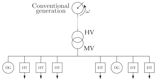
Multiple HDTs, as shown in Figure 6, can be coordinated in order to regulate the voltage magnitude of the medium-voltage buses, while optimizing the reactive power injection/consumption of the HDTs. This task can be done in a decentralized manner, utilizing HDTs controlled with local variables, exclusively [43].

Figure 6. Active distribution grid voltage regulation by means of HDTs.
References
- Gönen, T. Electric Power Distribution System Engineering, 3rd ed.; CRC Press: Boca Raton, FL, USA, 2014.
- Ciuriuc, A.; Dumitran, L.M.; Notingher, P.V.; Badicu, L.V.; Setnescu, R.; Setnescu, T. Lifetime Estimation of Vegetable and Mineral Oil Impregnated Paper for Power Transformers. In Proceedings of the 2016 IEEE International Conference on Dielectrics (ICD), Montpellier, France, 3–7 July 2016; Volume 2, pp. 720–723.
- Fuchs, E.; Masoum, M. Power Quality in Power Systems and Electrical Machines, 2nd ed.; Academic Press: Cambridge, MA, USA, 2015.
- IEEE. IEEE Recommended Practice for Monitoring Electric Power Quality, IEEE Std 1159-2019; IEEE: New York, NY, USA, 2019; pp. 1–98.
- IEEE. IEEE Recommended Practice and Requirements for Harmonic Control in Electric Power Systems, IEEE Std 519-2014; IEEE: New York, NY, USA, 2014; pp. 1–29.
- Singh, B.; Chandra, A.; Al-Haddad, K. Power Quality: Problems and Mitigation Techniques; Wiley: Hoboken, NJ, USA, 2015.
- Sharma, A.; Rajpurohit, B.S.; Singh, S.N. A Review on Economics of Power Quality: Impact, Assessment and Mitigation. Renew. Sustain. Energy Rev. 2018, 88, 363–372.
- IEEE. IEEE Recommended Practice for Establishing Liquid Immersed and Dry-Type Power and Distribution Transformer Capability When Supplying Nonsinusoidal Load Currents, IEEE Std C57.110-2018; IEEE: New York, NY, USA, 2018; pp. 1–68.
- Kefalas, T.D.; Kladas, A.G. Harmonic Impact on Distribution Transformer No-Load Loss. IEEE Trans. Ind. Electron. 2010, 57, 193–200.
- Dao, T.; Phung, B.T. Effects of Voltage Harmonic on Losses and Temperature Rise in Distribution Transformers. IET Gener. Transm. Distrib. 2018, 12, 347–354.
- Mazzanti, G.; Lusetti, L.; Fragiacomo, A. The State of the Art About Electric Arc Furnaces for Steel Use and the Compensation of Their Perturbing Effects on the Grid. In Proceedings of the International Symposium on Power Electronics Power Electronics, Electrical Drives, Automation and Motion, Sorrento, Italy, 20–22 June 2012; pp. 1277–1282.
- Awadallah, M.A.; Venkatesh, B.; Singh, B.N. Impact of Solar Panels on Power Quality of Distribution Networks and Transformers. Can. J. Electr. Comput. Eng. 2015, 38, 45–51.
- Ustun, T.S.; Hashimoto, J.; Otani, K. Impact of Smart Inverters on Feeder Hosting Capacity of Distribution Networks. IEEE Access 2019, 7, 163526–163536.
- Kraiczy, M.; Stetz, T.; Braun, M. Parallel Operation of Transformers With on Load Tap Changer and Photovoltaic Systems With Reactive Power Control. IEEE Trans. Smart Grid 2018, 9, 6419–6428.
- Paterakis, N.G.; Pappi, I.N.; Erdinc, O.; Godina, R.; Rodrigues, E.M.G.; Catalao, J.P.S. Consideration of the Impacts of a Smart Neighborhood Load on Transformer Aging. IEEE Trans. Smart Grid 2016, 7, 2793–2802.
- Hilshey, A.D.; Hines, P.D.; Rezaei, P.; Dowds, J.R. Estimating the Impact of Electric Vehicle Smart Charging on Distribution Transformer Aging. IEEE Trans. Smart Grid 2013, 4, 905–913.
- Santos-Martin, D.; Lemon, S.; Watson, J.D.; Wood, A.R.; Miller, A.J.; Watson, N.R. Impact of Solar Photovoltaics on the Low-Voltage Distribution Network in New Zealand. IET Gener. Transm. Distrib. 2016, 10, 1–9.
- Gong, Q.; Midlam-Mohler, S.; Marano, V.; Rizzoni, G. Study of PEV Charging on Residential Distribution Transformer Life. IEEE Trans. Smart Grid 2012, 3, 404–412.
- Faiz, J.; Siahkolah, B. Electronic Tap-Changer for Distribution Transformers; Springer: Berlin/Heidelberg, Germany, 2011.
- Das, B.P.; Radakovic, Z. Is Transformer kVA Derating Always Required Under Harmonics? A Manufacturer’s Perspective. IEEE Trans. Power Deliv. 2018, 33, 2693–2699.
- Abu-Siada, A.; Budiri, J.; Abdou, A. Solid State Transformers Topologies, Controllers, and Applications: State-of-the-Art Literature Review. Electronics 2018, 7, 298.
- Huber, J.E.; Kolar, J.W. Solid-State Transformers: On the Origins and Evolution of Key Concepts. IEEE Ind. Electron. Mag. 2016, 10, 19–28.
- Huang, A.; Zhu, Q.; Wang, L.; Zhang, L. 15 kV SiC MOSFET: An Enabling Technology for Medium Voltage Solid State Transformers. CPSS Trans. Power Electron. Appl. 2017, 2, 118–130.
- Bala, S.; Das, D.; Aeloiza, E.; Maitra, A.; Rajagopalan, S. Hybrid Distribution Transformer: Concept Development and Field Demonstration. In Proceedings of the 2012 IEEE Energy Conversion Congress and Exposition (ECCE), Raleigh, NC, USA, 15–20 September 2012; pp. 4061–4068.
- Burkard, J.; Biela, J. Hybrid Transformers for Power Quality Enhancements in Distribution Grids—Comparison to Alternative Concepts. In Proceedings of the NEIS 2018; Conference on Sustainable Energy Supply and Energy Storage Systems, Hamburg, Germany, 20–21 September 2018; pp. 1–6.
- Burkard, J.; Biela, J. Design of a Protection Concept for a 100kVA Hybrid Transformer. IEEE Trans. Power Electron. 2019, 35, 3543–3557.
- Burkard, J.; Biela, J. Protection of Hybrid Transformers in the Distribution Grid. In Proceedings of the 2016 18th European Conference on Power Electronics and Applications (EPE’16 ECCE Europe), Karlsruhe, Germany, 5–9 September 2016; pp. 1–10.
- Sastry, J.; Bala, S. Considerations for the Design of Power Electronic Modules for Hybrid Distribution Transformers. In Proceedings of the 2013 IEEE Energy Conversion Congress and Exposition, ECCE 2013, Denver, CO, USA, 15–19 September 2013; pp. 1422–1428.
- Huber, J.E.; Kolar, J.W. Applicability of Solid-State Transformers in Today’s and Future Distribution Grids. IEEE Trans. Smart Grid 2019, 10, 317–326.
- Bala, S. Distribution Transformer. EU Patent PCT/US2013/056393, 23 August 2013.
- Haj-Maharsi, M.Y.; Sandeep, B.; Tang, L. Hybrid Distribution Transformer with an Integrated Voltage Source Converter. US Patent US 201O/O220499 A1, 2 February 2010.
- Haj-Maharsi, M.Y.; Tang, L.; Gutierrez, R.; Bala, S. Hybrid Distribution Transformer with AC & DC Power Capabilities. US Patent US 2010/0201338 A1, 12 August 2010.
- Haj-Maharsi, M.Y.; Tang, L.; Gutierrez, R.; Bala, S. Hybrid Distribution Transformer Having a Power Electronic Module for Controlling Input Power Factor and Output Voltage. US Patent US 9768704 B2, 19 September 2017.
- Burkard, J.; Biela, J. Transformer Inrush Current Mitigation Concept for Hybrid Transformers. In Proceedings of the IEEE 2017 19th European Conference on Power Electronics and Applications (EPE’17 ECCE Europe), Warsaw, Poland, 11–14 September 2017; Volume 2017, pp. 1–9.
- Chen, Z.; Li, H.; Liu, L.; Xiang, L.; Bai, B. DC Bias Treatment of Hybrid Type Transformer Based on Magnetic Flux Modulation Mechanism. IEEE Trans. Magn. 2019, 55, 1–4.
- Ramos-Ruiz, J.; Krishnamoorthy, H.; Enjeti, P. Adding Capacity to an Existing Electric Power Distribution Network Using a Solid State Transformer System. In Proceedings of the 2015 IEEE Energy Conversion Congress and Exposition (ECCE), Montreal, QC, Canada, 20–24 September 2015; pp. 6059–6066.
- Ramos-Ruiz, J.; Morsy, A.; Enjeti, P. Medium Voltage AC-AC Adapter Using Multilevel Capacitor Clamped Buck Converter. In Proceedings of the 2016 13th International Conference on Power Electronics (CIEP), Guanajuato, Mexico, 20–23 June 2016; pp. 35–40.
- Fernando, N.; Meegahapola, L.; Thilakarathne, C. Solid State Transformer Parallel Operation With a Tap Changing Line Frequency Transformer. In Proceedings of the 2017 IEEE Innovative Smart Grid Technologies—Asia (ISGT-Asia), Auckland, New Zealand, 27–30 November 2018; pp. 1–6.
- Baier, C.R.; Torres, M.A.; Perez, M.A.; Cárdenas, R.; Ramirez, R.; Melín, P. Hybrid Transformers with Virtual Inertia for Future Distribution Networks. In Proceedings of the IECON 2019—45th Annual Conference of the IEEE Industrial Electronics Society, Lisbon, Portugal, 14–17 October 2019; pp. 6767–6772.
- Shao, H.; Cai, X.; Zhou, D.; Li, Z.; Zheng, D.; Cao, Y.; Wang, Y.; Rao, F. Equivalent Modeling and Comprehensive Evaluation of Inertia Emulation Control Strategy for DFIG Wind Turbine Generator. IEEE Access 2019, 7, 64798–64811.
- Kerdphol, T.; Rahman, F.S.; Watanabe, M.; Mitani, Y. Robust Virtual Inertia Control of a Low Inertia Microgrid Considering Frequency Measurement Effects. IEEE Access 2019, 7, 57550–57560.
- Zhu, R.; De Carne, G.; Deng, F.; Liserre, M. Integration of Large Photovoltaic and Wind System by Means of Smart Transformer. IEEE Trans. Ind. Electron. 2017, 64, 8928–8938.
- Kou, P.; Liang, D.; Gao, R.; Liu, Y.; Gao, L. Decentralized Model Predictive Control of Hybrid Distribution Transformers for Voltage Regulation in Active Distribution Networks. IEEE Trans. Sustain. Energy 2019, 11, 2189–2200.


