Your browser does not fully support modern features. Please upgrade for a smoother experience.

Submitted Successfully!
Thank you for your contribution! You can also upload a video entry or images related to this topic.
For video creation, please contact our Academic Video Service.
| Version | Summary | Created by | Modification | Content Size | Created at | Operation |
|---|---|---|---|---|---|---|
| 1 | Joel Zagoya | + 1926 word(s) | 1926 | 2021-06-21 05:57:39 | | | |
| 2 | Bruce Ren | -21 word(s) | 1905 | 2021-06-29 06:01:32 | | |
Video Upload Options
We provide professional Academic Video Service to translate complex research into visually appealing presentations. Would you like to try it?
Cite
If you have any further questions, please contact Encyclopedia Editorial Office.
Zagoya, J. Foot/Ankle Prostheses Design Approach. Encyclopedia. Available online: https://encyclopedia.pub/entry/11425 (accessed on 08 February 2026).
Zagoya J. Foot/Ankle Prostheses Design Approach. Encyclopedia. Available at: https://encyclopedia.pub/entry/11425. Accessed February 08, 2026.
Zagoya, Joel. "Foot/Ankle Prostheses Design Approach" Encyclopedia, https://encyclopedia.pub/entry/11425 (accessed February 08, 2026).
Zagoya, J. (2021, June 29). Foot/Ankle Prostheses Design Approach. In Encyclopedia. https://encyclopedia.pub/entry/11425
Zagoya, Joel. "Foot/Ankle Prostheses Design Approach." Encyclopedia. Web. 29 June, 2021.
Copy Citation
There are different alternatives when selecting removable prostheses for below the knee amputated patients. The designs of these prostheses vary according to their different functions. These prostheses designs can be classified into Energy Storing and Return (ESAR), Controlled Energy Storing and Return (CESR), active, and hybrid. This paper aims to identify the state of the art related to the design of these prostheses of which ESAR prostheses are grouped into five types, and active and CESR are categorized into four groups. Regarding patent analysis, 324 were analyzed over the last six years.
ankle prosthesis
prosthetic foot
lower limb rehabilitation
below-knee amputee
1. Introduction
Below-knee amputation (BKA) is a surgical procedure that mainly originates from trauma, diabetes, and peripheral vascular diseases [1]. While it is estimated that an average person walks about 6500 steps per day, current trends suggest that 10,000 steps per day represent a healthy lifestyle [2] for which a suitable prosthesis is necessary for a BKA patient in order to achieve a complete user reintegration to his/her pre-amputation activities. These designs should adapt to different patient’s activities.
In scientific documents, there is wide confusion with the terms prosthesis, prosthetic, and prostheses; prosthetic is the process to manufacture an artificial member (AM), prosthesis a component of the AM, and prostheses are all the components that make up an AM. From patents and scientific document searches, the term prosthesis is more commonly used; in this paper, prostheses and prosthesis will be used interchangeably.
Understanding the functioning of these prostheses is necessary to identify the foot movements: internal–external axial rotation, eversion–inversion, dorsiflexion (DF), and plantarflexion (PF), as shown in Figure 1. The forces acting on the human foot are distributed with 60% towards the heel and 40% towards the phalanges. The loads are distributed between the heel and the metatarsals to the fourth and fifth phalanges and towards the big toe to the second and third phalanges [3].
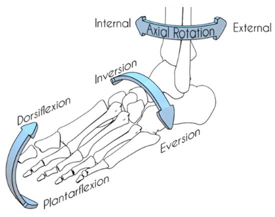
Figure 1. Different movements of the foot.
In order to improve and develop ankle/foot prostheses, it is necessary to know and understand present-day solutions to walking and running for BKA patients (and the people behind those solutions), so our designs meet both user and technical requirements. A state-of-the-art analysis of BKA prostheses is performed in this research.
Foot prostheses can be classified as follows:
-
Ankle-cushion heel (SACH-foot): This was developed in the 1950s and incorporated a compressible heel that dampens the impact on the ground while emulating a plantarflexion movement. This type of prosthesis is used for its relatively low cost and weight [4].
-
ESAR, also known as ESR, was developed in the 1980s. This type of prosthesis uses a foot-modeled plate (usually carbon fiber made) that stores elastic potential energy and progressively releases it as kinetic energy [5].
-
CESR prostheses aim to capture the energy that is dissipated during a gait impact. On the loading phase of stance, energy is stored by a spring and locked. Then, this energy is timely released during the terminal stance of walking using microelectronic components [5].
-
Active prostheses are considered state-of-the-art prostheses due to the use of actuators, microcontrollers, or other electronic devices; usually, these work using ESAR foot systems combined with some external elements such as actuators or other electronic components. These prostheses have better control and stability during a walk cycle [6].
2. Device Classification
From the selected patents and scientific documentation, a new ankle/foot prosthesis classification has been created besides ESAR, CERS, and active, based on its components and prosthesis functions.
ESAR prostheses are categorized into five different designs (see Figure 1). CERS and active categories are merged and divided into five different categories. There are some unique designs whose components cannot be grouped; these will be discussed individually.

Figure 1. (A) General form of ESAR prosthesis, (B) Modified ESAR prosthesis, (C) ESAR with split plates, (D) ESAR prosthesis with cushions, (E) ESAR with damping system.
From the previous analyses, it can be determined that the general form for ESAR prosthesis is similar to the one illustrated in Figure 1A and mostly differs in form; sometimes, a single talon plate is aggregated, or the disposition of the plates may vary. In other cases, as in Figure 1B, the center of mass is moved, and the plates are rearranged. In the variation represented by Figure 1C, the foot plates are divided, so the prosthesis emulates eversion and inversion movements. In Figure 1D, some polymeric cushions are aggregated, replacing the use of extra plates. Figure 1E shows the usage of different types of damping systems (springs, actuators, etc.) that replace some plates. All of these designs use pyramid adapters as a connection between the prosthesis and transtibial components.
There are some variations for ESAR prostheses that use a simple plate arrangement to adjust the return of energy (see Figure 2A). Other designs use a single spring bar that regulates the energy storage/release (see Figure 2B).
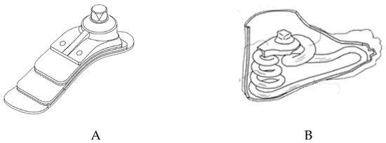
Figure 2. (A) Multiple plates prosthesis, (B) Single spring prosthesis by Kim Sa Yeop [7].
For CERS prosthesis, the model by Endo Ken [8] (see Figure 3) considers a locking mechanism that preserves the energy storage in the spring. This energy is released upon the foot movement during the terminal stance. This impulse, in combination with the ESAR foot, provides necessary torque during the walk cycle.
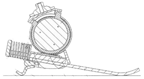
Figure 3. CERS prosthesis by Endo Ken [8].
Active prostheses can be categorized by the components they use into three types: Multi-Array Prostheses (MAP), Low Powered Prostheses (LPP), and Controlled Adaptative Stiffness (CAS). For MAP, the form is similar to the one shown in Figure 4. It uses an ESAR composite foot (E), and a DC motor (A), usually a 200 W Maxon® connected to a ball-screw transmission (C) that moves the linkage system (D) upward/downward and converts motor rotary motion into linear motion. In some cases, the motor is located instead of the spring (G) and connected to (C) using a timing belt. The linkage system (D) is in charge of connecting different mechanisms and allows plantarflexion and dorsiflexion movements; it may be composed of cables and/or pulleys, a bar mechanism, or crank sliders. F and G, depending on the prostheses, represent springs or actuators (pneumatic, electric, or hydraulic), for which torque varies from 100 to 140 Nm. Sometimes a parallel spring is aggregated due to the demanding torque requirements, and it aims to reduce the loads supported by the linkage system. Spring (G) saves energy during plantarflexion and dorsiflexion and supplements it during the swing phase. Housing (B) allocates all the electronic systems and provides stability to the system. The pyramid adapter (H) provides a connection between the transtibial components and the prosthesis. Some models have a lock mechanism, so the prosthesis could be used in a passive mode. See Figure 4, Figure 5, Figure 13, Figure 6 and Figure 7.
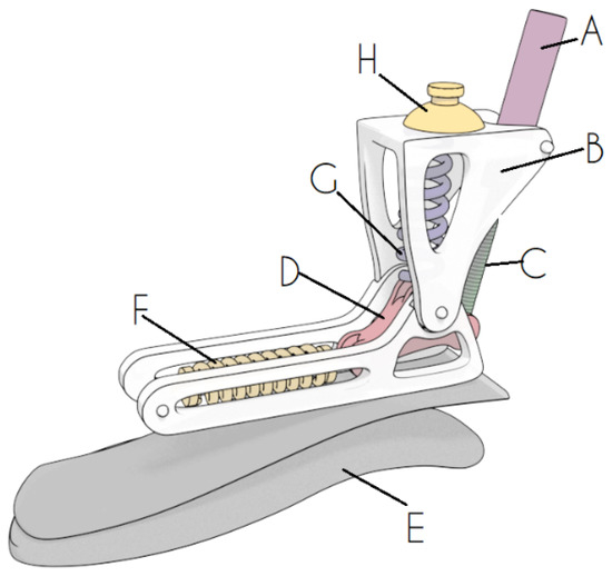
Figure 4. MAP active ankle–foot prosthesis.
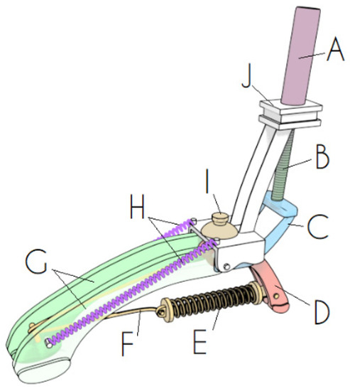
Figure 5. LPP active prosthesis.
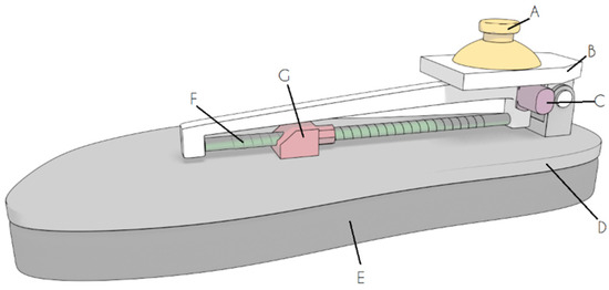
Figure 6. CAS Prosthesis.
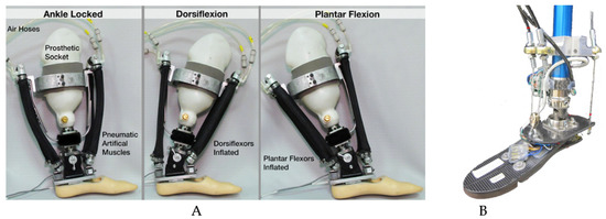
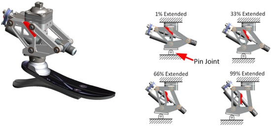
Figure 8. A robotic ankle–foot prosthesis by LaPre [11].
Another powered prosthesis design is the LPP shown in Figure 5. It aims to reduce the necessary power required by the actuators. It contains different Footplates (G and C), which in some designs (similar to the AMP Foot 2.1 [12]) are merged into a single plate. In another case such as the VSPA Foot [13], footplates (G) are individually controlled, allowing eversion–inversion movements; the DC motor (A) is located in a Housing (J) and rotates the Ball screw transmission (B), which moves the Footplate (C) up or down, allowing plantarflexion and dorsiflexion movement. Heel (D) may be composed of a flexible plate; ankle stiffness is provided by Springs (H) and (E). Depending on the model, two Springs (H) are used when there are individually controlled Footplates, and Spring (E) is used when (G) and (C) are merged. In this case, Spring (E) is attached directly to Footplate (C). Spring (E) is elongated using a Pulley system (F) connected to the Footplate (C). The pyramid adapter (I) provides a connection between the transtibial components and the prosthesis. Designs for this model use an external power supply that is not integrated into the main prosthesis body.
CAS prostheses (see Figure 6) are mainly based on an ESAR foot (D), and in some cases complemented with a Cushion (E). The main goal of this prosthesis is the modulation of the stiffness during different stages of a gait cycle. This is granted by moving a Slider (G) along the length of the foot. Depending on the gait cycle, this slider moves forward and backward, providing the necessary stiffness to adapt to different situations such as walking, running, or climbing stairs, and it is controlled by a DC motor (C). A linkage system could be provided by a Ball screw transmission (F) or pulleys and belts. Motor (C) could be programmed to adapt to different activities. Housing (B) provides support for all the components and allows one degree of freedom (DOF) for the foot. The pyramid adapter (A) provides a connection between the transtibial components and the prosthesis.
3. Other Designs
Some designs do not correspond to the categories previously described. These designs are the pneumatic foot prosthesis by Huang et al. [9] (see Figure 7A), where DF and PF are managed by two artificial muscles each, so stiffness and PF torque are easier to control. It is capable of emulating 3 DOF and is controlled via a desktop computer. Another design is the two DOF cable-driven ankle–foot prosthesis by Ficanha et al. [10], where instead of using pneumatic systems, it uses pulleys and Bowden cables that are externally controlled by two motors (Maxon EC-4), see Figure 7B. Both systems have an external power source and are capable of emulating foot eversion and inversion movements.
Another case is the robotic foot prosthesis made by Lapre [11]. This device aims to actively align the foot during different stances of the gait cycle using a four-bar linkage system to rotate and translate the foot with the use of a single actuator. It works using an ESAR foot and a DC motor (Maxon® EC-30 200 W) that moves a Ball screw transmission via a belt drive. As this actuator system (motor and ball screw) contracts, it extends and shifts the foot center (see Figure 8).
4. ESAR Analysis
Most of the active prostheses use ESAR foot to generate enough power to initiate the gait cycle. From the patentometric and scientometric analysis, it is evident that types A, B, and C are the most used (see Figure 1). A structural analysis was performed to make a comparison between these types. Carbon-fiber footplates and a concrete floor were used. A load of 785 N was applied on the prosthesis upper faces obtaining a maximum deformation on the Y-axis of 0.63, 0.33, and 0.67 mm for types A, B, and C, respectively (see Figure 9). Meanwhile, deformations on A and C mostly occur on the ankle; B shows major flexibility along the foot. The red color shows maximum displacements on the foot connection with the body, but blue shows no deformation.

Figure 9. Comparative static analysis of ESAR prosthesis.
According to the structural analysis, B tends to offer major elastic energy compared to A and C, as shown in the instep colored in green/blue.
To compare the effectiveness during a walk cycle on uneven terrain, prostheses A, B, and C were analyzed using the same velocity and loads. Figure 10 shows a clear advantage of (C) over the other two models, thanks to the uneven deformation on its divided footplates, as shown for the displacement colored in red.

Figure 10. Results of deformations on uneven terrain.
References
- Biddiss, E.A.; Chau, T.T. Upper limb prosthesis use and abandonment. Prosthet. Orthot. Int. 2007, 31, 236–257.
- Tudor-Locke, C.; Bassett, D.R. How many steps/day are enough? Sports Med. 2004, 34, 1–8.
- Brosky, J.; Balazsy, J. Functional Anatomy of the Foot and Ankle; Elsevier: Amsterdam, The Netherland, 2017; pp. 581–586.
- Geeroms, J. Study and Design of an Actuated Below-Knee Prosthesis. Master’s Thesis, Vrije Universiteit, Brussels, Belgium, June 2011.
- Hafner, B.J.; E Sanders, J.; Czerniecki, J.M.; Fergason, J. Transtibial energy-storage-and-return prosthetic devices: A review of energy concepts and a proposed nomenclature. J. Rehabil. Res. Dev. 2002, 39, 1–11.
- Gutfleisch, O. Peg legs andbionic limbs: The development of lower extremity prosthetics. Interdiscip. Sci. Rev. 2003, 28, 139–148.
- Kim, S.Y. Prosthetic Foot and Manufacturing Method Thereof. KR1020160127875, 5 December 2016.
- Endo, K. Movement Support Apparatus. EP 2823792 B1, 21 March 2018.
- Huang, S.; Wensman, J.P.; Ferris, D. An experimental powered lower limb prosthesis using proportional myoelectric control. J. Med Devices 2014, 8, 024501.
- Rice, J.J.; Schimmels, J.M.; Huang, S. Design and evaluation of a passive ankle prosthesis with powered push-off. J. Mech. Robot. 2015, 8, 021012.
- Rábago, C.A.; Whitehead, J.A.; Wilken, J.M. Evaluation of a powered ankle-foot prosthesis during slope ascent gait. PLoS ONE 2016, 11, e0166815.
- Cherelle, P.; Junius, K.; Grosu, V.; Cuypers, H.; VanderBorght, B.; Lefeber, D. The AMP-Foot 2.1: Actuator design, control and experiments with an amputee. Robotica 2014, 32, 1347–1361.
- Dong, D.; Ge, W.; Liu, S.; Xia, F.; Sun, Y. Design and optimization of a powered ankle-foot prosthesis using a geared five-bar spring mechanism. Int. J. Adv. Robot. Syst. 2017, 14, 1–12.
More
Information
Subjects:
Engineering, Biomedical; Orthopedics
Contributor
MDPI registered users' name will be linked to their SciProfiles pages. To register with us, please refer to https://encyclopedia.pub/register
:
View Times:
1.6K
Revisions:
2 times
(View History)
Update Date:
29 Jun 2021
Notice
You are not a member of the advisory board for this topic. If you want to update advisory board member profile, please contact office@encyclopedia.pub.
OK
Confirm
Only members of the Encyclopedia advisory board for this topic are allowed to note entries. Would you like to become an advisory board member of the Encyclopedia?
Yes
No
${ textCharacter }/${ maxCharacter }
Submit
Cancel
Back
Comments
${ item }
|
More
No more~
There is no comment~
${ textCharacter }/${ maxCharacter }
Submit
Cancel
${ selectedItem.replyTextCharacter }/${ selectedItem.replyMaxCharacter }
Submit
Cancel
Confirm
Are you sure to Delete?
Yes
No


