
| Version | Summary | Created by | Modification | Content Size | Created at | Operation |
|---|---|---|---|---|---|---|
| 1 | Jan Flek | + 2118 word(s) | 2118 | 2021-05-31 10:38:27 | | | |
| 2 | Conner Chen | -140 word(s) | 1978 | 2021-06-08 13:20:41 | | |
Video Upload Options
Properly designed gear geometry has a positive effect on the dynamic response of the system, which can be observed on the frequency spectrum of the investigated dynamic system. This geometry has a noticeable effect on the reduced emission of noise in around. What is manifested in the frequency spectrum of gears is mainly the effect of internal excitation caused by the mesh stiffness, which changes during the meshing and thus interferes with the course of torsional dynamic processes of the gear systems. It is therefore necessary to take into account the mesh stiffness when designing the gearbox and to incorporate its course into the dynamic equations of motion. There are various ways to visualize, simulate, and calculate the course of mesh stiffness of gearing. There are different variants of analytical calculations. One of the variants of analytical modeling is the possibility of calculating the mesh stiffness by calculating the deformation energy of individual teeth of the gear.
1. Analytical Models of Mesh Stiffness
In this chapter, two different possibilities of how to model the course of mesh stiffness can be analytically approached. The mesh stiffness is based on the geometric and material properties of the gear teeth and is time-varying due to the meshing of the gears. This is the relationship between the load of the tooth and its deformation, while the tooth is considered as a cantilever beam with a variable cross-section, where a force acts in the direction of the line of action. The mesh stiffness of single pair of teeth and double pairs of teeth in engagement alternates during the meshing of the gears (in this case, it is a spur gear with straight teeth).
In general, the stiffness of single pair of teeth can be described by the Equation (1):

where c is the stiffness of single pair of teeth in engagement, w denotes the load along the face width in the direction of the line of action and δ is the deformation of single pair of teeth, which corresponds to the load w.
Similarly, the stiffness of double pairs of teeth can be defined by Equation (1), with the load w being the sum of the load of the teeth of the first pair w1 and the load of the teeth of the second pair w2, which corresponds to the deformation δ.
1.1. Analytical Model by ISO Standard
The analytical calculation model (AM1), which is described in this paragraph, is based on the publications of the Czech authors Čestmír Šalamoun [1] and Vladimír Moravec [2]. This model is still widely used in research of gearing dynamics. Other authors who mention this model in their publications are Wan, Cao, Zi, He and He [3], Yu and Machefske [4] and, last but not least, Velex [5]. This is a model that is not universally applicable and is very approximate. It was derived from the testing of many gear samples and can be described as a computational model based on empirical relationships. It is useable when it is not absolutely necessary to create perfectly accurate dynamic models of transmission systems and we are only interested in approximate values of the stiffness of single pair of teeth and double pair of teeth in engagement.
The stiffness of single pair in contact was determined by Equation (2):

where z1, z2 denote the number of teeth of pinion and gear, x1, x2 are profile shift coefficients of the pinion and gear. The individual empirical constants C1–C9 are listed in the Table 1.
Table 1. Constants for calculating the stiffness of single pair of teeth [1][2].
| C1 | C2 | C3 | C4 | C5 | C6 | C7 | C8 | C9 |
|---|---|---|---|---|---|---|---|---|
| 0.04723 | 0.15551 | 0.25791 | 0.00635 | 0.11654 | 0.00193 | 0.24188 | 0.00529 | 0.00182 |
From the point of view of the simplicity of the stiffness calculation of double pair of teeth, the calculation relation for determining the stiffness of double pairs of teeth is convenient as well. In publications [1][2], this stiffness is called the engagement stiffness and is again the approximate value of the stiffness of double pairs of teeth in engagement.
This engagement stiffness implies from the Equation (3):

cγ denotes the stiffness of double pair of teeth or engagement stiffness, c′ is the stiffness of single pair of teeth in engagement given by the computational relation—Equation (2) and ϵ is the designation of the engagement factor or contact ratio of gear.
Using Equations (2) and (3), there are obtained two approximate values that correspond to the stiffness of single and double pairs of teeth in the engagement. The values related to the face width are given as a result of its calculation. These values have unit N/mm2. To obtain real values that correspond to the time-varying mesh stiffness with the unit N/m, we must multiply the stiffness c′ and cγ by the actual face width in millimeters and then convert N/mm to N/m.
Figure 1 shows the theoretical course of mesh stiffness of gearing during an engagement. From the calculation of relations Equations (2) and (3), the constant values of the stiffness of single and double pairs of teeth are obtained. In order to obtain a similar course of mesh stiffness as in Figure 1, it is necessary to use the prescription of the Fourier series, which allows plotting the course of mesh stiffness with periodic alternation of the stiffness of single and double pairs of teeth in engagement.
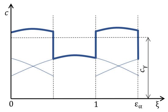
Figure 1. The course of the total stiffness of spur gearing [1].
The Fourier series has the form (4) [6]:

where ϵ is contact ratio of gearing, m is equal to 1 for the case of calculating the course of stiffness of the gearing with staight teeth, τ is dimensionless time.
When using this analytical approach, it is necessary to keep in mind its limitations. Since this analytical model is determined on the basis of test samples and is given by empirical relationships, it has its natural initial conditions for its use. Gears must meet the following conditions:
-
1.the gear must have external gearing,
-
2.the gearing must be straight teethed, helix angle of reference circle β=0,
-
3.gears must have a standard basic profile:
-
pressure angle α=20∘
-
addendum coefficient ha0=1.2
-
dedendum coefficient hf0=1.0
-
tooth root radius ρ0=0.2
-
-
4.The following must apply to the profile shift coefficients of gearing:
-
x1≥x2
-
−0.5≤xΣ≤2.0
-
1.2. Analytical Model in Terms of Deformation Energy
Across various sources in the form of scientific articles, the method of deformation energy is considered to be the ideal analytical approach to modeling the stiffness of gears, as an internal excitation element of dynamical systems. The following findings are summarized from the authors’ scientific contributions: Chen and Shao [7]; Saxena, Chouksey and Parey [8]; Sainsot, Velex and Duverger [9]; Cao, Chen and Jiang [10]; Yang et al. [11] and last but not least Wan, Cao, Zi, He and He [3]. The second analytical model (AM2) for obtaining the course of mesh stiffness of gear is a model based on the mentioned publications. In this case, it is not an empirical model, which was created on the basis of experimental testing of gear samples, but is directly based on the theory of elasticity. The individual teeth are considered as cantilever beams placed in the dendum circle with a variable cross-section, where a force acts in the direction of the line of action. The deformation energy accumulated in the tooth is calculated individually for each tooth coming into an engagement. The potential energies that contribute to the calculation of gear stiffness are: bending energy Ub, shear energy Us, and axial compressive energy Ua. They can be determined using Equation (5).

Kb, Ks and Ka denote the bending, shear and axial compressive stiffness. F is the force in direction of line of action.
By means of beam theory, the calculation of the potential energy for a gear tooth can be defined using these Equation (6)

where E is Young modulus, G denotes shear modulus and Ax,Ix represent the area of cross-section and moment area of inertia where the distance between the section and the acting point of the applied force is x which is from interval <0;d> which shows Figure 2 [7].
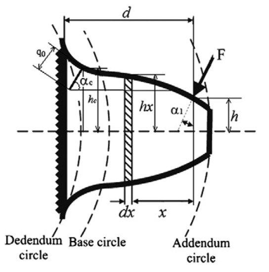
Figure 2. Geometrical parameters for mesh stiffness calculation [7].
Fb,Fa and M can be calculated from the following Equation (7).

The required stiffnesses (8) can be calculated from Equations (5)–(7).

The contact stiffness is also reflected in the overall mesh stiffness of the gearing. This stiffness is referred to a Hertzian contact stiffness Kh. This stiffness is calculated as follows:

where ν is Poisson’s ratio, W is face width.
The last thing that affects the mesh stiffness of gearing is called fillet-foundation stiffness Kf. It is an expression of stiffness that takes into account the fillet radius, which is given by Equation (10).

There is δf in Equation (10). This expresses the deformation of the tooth at its fillet radius and a special Equation (11) using empirical constants is used to calculate it.

The coefficients L∗, M∗, P∗, Q∗ are given by a general polynomial function (Equation (12)), where X∗ represents the individual coefficients.

Empirical values of Ai, Bi, Ci, Di, Ei, Fi are given in the Table 2. In Equation (12), hfi is equal to rf/rint. The unmentioned members of Equations (11) and (12) are shown in the Figure 3 for complete information.
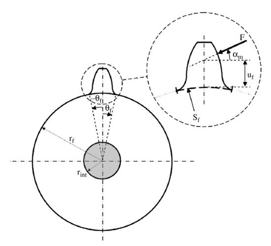
Figure 3. Geometrical parameters for fillet-foundation stiffness calculation [7].
Table 2. Constants for calculating the deformation of fillet-foundation [7].
| Ai | Bi | Ci | Di | Ei | Fi | |
|---|---|---|---|---|---|---|
| L∗ | −5.574×10⁻⁵ | −1.9986×10⁻³ | −2.3015×10⁻⁴ | 4.7702×10⁻³ | 0.0271 | 6.8045 |
| M∗ | 60.111×10⁻⁵ | 28.100×10⁻³ | −83.431×10⁻⁴ | −9.9256×10⁻³ | 0.1624 | 0.9086 |
| P∗ | −50.952×10⁻⁵ | 185.50×10⁻³ | 0.0538×10⁻⁴ | 53.3×10⁻³ | 0.2895 | 0.9236 |
| Q∗ | −6.2042×10⁻⁵ | 9.0889×10⁻³ | −4.0964×10⁻⁴ | 7.8297×10⁻³ | −0.1472 | 0.6904 |
The total stiffness of single pair of teeth in the engagement is calculated as:

The total stiffness of double pairs of teeth in engagement is determined by the Equation (14) [12]:

2. FEM Model
Firstly, according to the design calculation of gears, five models of gearing with a real teeth shape were created (Gearing 1, 2, 3, 4, 5), because of the calculation, simulation, and subsequent comparison of the engagement of gears and pinions. The basic parameters of these designed gears are listed in the Table 3. Gearing 1, 2, 3, and 4 are based on one designed gearing. The individual variants differ from each other only by the selected different profile shift coefficients x1 and x2. Real tooth profiles of gears 1–4 are shown in the Figure 4.
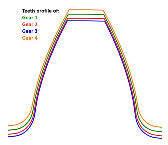
Figure 4. Gear teeth profiles of Gearing 1–Gearing 4.
Table 3. The basic parameters of designed gearings.
| mn [mm] | z1[−] | z2[−] | x1[−] | x2[−] | b [mm] | αn[∘] | β[∘] | |
|---|---|---|---|---|---|---|---|---|
| Gearing 1 | 1.5 | 29 | 30 | 0.2696 | 0.2606 | 23 | 20 | 0 |
| Gearing 2 | 1.5 | 29 | 30 | 0.35 | 0.1802 | 23 | 20 | 0 |
| Gearing 3 | 1.5 | 29 | 30 | 0.4 | 0.1302 | 23 | 20 | 0 |
| Gearing 4 | 1.5 | 29 | 30 | 0.1823 | 0.3479 | 23 | 20 | 0 |
| Gearing 5 | 16 | 13 | 13 | 0 | 0 | 6 | 20 | 0 |
Gearing 5 is a gearing that is not typical. Due to the atypical shape of the fillet-foundation, the tooth profile can’t be produced by a standard gear hob. These teeth are not usable in practice, but in this article, they will be used to compare the results and define the validity of the theoretical approach. The tooth profile of the gear 5 is shown in Figure 5.
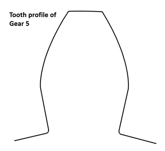
Figure 5. Gear tooth profile of Gearing 5.
Furthermore, the model for the subsequent calculation was simplified by not modeling the whole wheels, but only their sections, which contain four teeth for the pinion and the wheel, which come into the common engagement. This is shown in the Figure 6. Single-pair and double-pair contact of the teeth was realized on these four pairs of teeth, by defining the contacts on the flanks of the teeth and the subsequent rolling of the pinion and the gear. The individual gearbox members (pinion and wheel) were converted from solid models to surfaces. These surfaces were further subdivided into smaller sections, mainly because of creating a better mesh of surface elements in the Abaqus CAE software in which the calculation was performed.
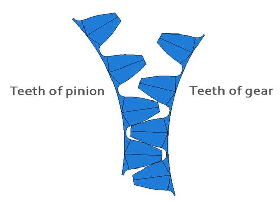
Figure 6. Abaqus CAE: the four-tooth engagement model.
For the calculation, boundary conditions are determined, which take into account the placement of the pinion and gear (only rotation about its own axis of rotation is allowed) and also contain predefined rotations of pinion and gear, which are used to demarcate tooth backlash and subsequently for the common rotation. In three computational steps, the boundary conditions and the torque load (100 Nm) of the wheel are gradually realized.
The very fine mesh of pinions (111,968 elements) and gears (83,952 elements) is formed by elements of the CPS8R type, i.e., quadrangular elements suitable for planar stress.
Based on the FEM analysis, the deformation rotation of the pinion and the gear was determined. Then it was converted to the stiffness of spare compression springs inserted between perfectly rigid teeth. This obtained the stiffness of the gears in the N/m units.
The resulting stiffness kc obtained from the FEM calculation was determined from the Equation (15)

where kp is the stiffness of the pinion teeth and kg is the stiffness of the gear teeth. The stiffnesses kp and kg depend on the load and the deformation rotation of pinion δp and gear δg, which are the result of the FEM analysis.
References
- Šalamoun, C. Čelní a šroubová soukolí s evolventním ozubením, 1st ed.; SNTL—Státní nakladatelství technické literatury: Prague, Czech Republi, 1990.
- Moravec, V. Konstrukce strojů a zařízení II.: Čelní ozubená kola: Teorie, výpočet, konstrukce, výroba, kontrola, 1st ed.; Montanex: Ostrava, Czech Republi, 2001.
- Wan, Z.; Cao, H.; Zi, Y.; He, W.; He, Z. An improved time-varying mesh stiffness algorithm and dynamic modeling of gear-rotor system with tooth root crack. Eng. Fail. Anal. 2014, 42, 157–177.
- Yu, W.; Mechefske, C.K. A New Model for the Single Mesh Stiffness Calculation of Helical Gears Using the Slicing Principle. Iran. J. Sci. Technol. Trans. Mech. Eng. 2019, 43, 503–515.
- Philippe, V. On the Modelling of Spur and Helical Gear Dynamic Behaviour. In Mechanical Engineering; Gokcek, M., Ed.; IntechOpen: Rijeka, Croatia, 2012; Chapter 4.
- Slavík, J.; Stejskal, V.; Zeman, V. Základy dynamicky strojů, 1st ed.; Vydavatelství ČVUT: Praha, Czech Republi, 1997.
- Chen, Z.; Shao, Y. Dynamic simulation of spur gear with tooth root crack propagating along tooth width and crack depth. Eng. Fail. Anal. 2011, 18, 2149–2164.
- Saxena, A.; Chouksey, M.; Parey, A. Effect of mesh stiffness of healthy and cracked gear tooth on modal frequency response characteristics of geared rotor system. Mech. Mach. Theory 2017, 107, 261–273.
- Sainsot, P.; Velex, P.; Duverger, O. Contribution of Gear Body to Tooth Deflections—A New Bidimensional Analytical Formula. J. Mech. Des. 2004, 126, 748–752.
- Cao, Z.; Chen, Z.; Jiang, H. Nonlinear dynamics of a spur gear pair with force-dependent mesh stiffness. Nonlinear Dyn. 2020, 99, 1227–1241.
- Yang, L.T.; Shao, Y.M.; Jiang, W.W.; Zhang, L.K.; Wang, L.M.; Xu, J. Effects of Tooth Surface Crack Propagation on Meshing Stiffness and Vibration Characteristic of Spur Gear System. Appl. Sci. 2021, 11, 1968.
- Raghuwanshi, N.K.; Parey, A. A New Technique of Gear Mesh Stiffness Measurement Using Experimental Modal Analysis. J. Vib. Acoust. 2019, 141.


