 +1 credit
| Version | Summary | Created by | Modification | Content Size | Created at | Operation |
|---|---|---|---|---|---|---|
| 1 | Md Rafiul Abdussami | + 2822 word(s) | 2822 | 2021-04-14 09:53:48 | | | |
| 2 | Rita Xu | Meta information modification | 2822 | 2021-04-14 10:39:34 | | |
Video Upload Options
The evolving global landscape for electrical distribution and use created a need area for energy storage systems (ESS), making them among the fastest growing electrical power system products.
1. Introduction
The electrical power system is one of the only supply networks where the product— electricity—is consumed instantaneously after it is generated. It is mainly because a safe and reliable means to store electrical energy has been missing. The evolving global landscape for electrical distribution and use created a need for energy storage systems (ESSs), making them among the fastest-growing electrical power system products.
The maturity of electrical energy storage technologies can be divided into three categories: deployed, demonstrated, and early-stage technologies. Pumped hydro, compressed air energy storage, battery, and flywheel are examples of the deployed electric energy storage system. The demonstrated energy storage technologies include flow batteries and advanced Pb-acid, superconducting magnetic energy storage, and electrochemical capacitor. The early stage energy storage technologies are adiabatic compressed air energy storage (CAES), hydrogen, and synthetic natural gas. Among all the above-mentioned technologies, batteries and capacitors are susceptible to risks and safety issues [1].
A battery is an electrical energy storage system that can store a considerable amount of energy for a long duration. A battery management system (BMS) is a system control unit that is modeled to confirm the operational safety of the system battery pack [2][3][4]. The primary operation of a BMS is to safeguard the battery. Due to safety reasons, cell balancing, and aging issues, supervision of each cell is indispensable. Moreover, BMS ensures the preset corrective measures against any abnormal condition at the system infrastructure. Besides, since the system temperature affects the power consumption profile, BMS also confirms the proper procedure to control the system temperature.
In [5], authors discussed the battery management systems in electric and hybrid vehicles. The paper addresses concerns and challenges related to current BMSs. State evaluation of a battery, including state of charge, state of health, and state of life, is a critical task for a BMS. By reviewing the latest methodologies for the state evaluation of batteries, the future challenges for BMSs are presented, and possible solutions are proposed. In [6], authors discussed the battery management system hardware concepts. It focuses on the hardware aspects of battery management systems (BMS) for electric vehicles and stationary applications. In [7], it presented an enhanced multicell-to-multicell battery equalizer based on bipolar-resonant LC converter. Mathematical analysis and comparison with typical equalizers are provided to illustrate its high balancing speed and good efficiency.
In [8], it dealt with the susceptibility to electromagnetic interference (EMI) of battery management systems (BMSs) for Li-ion and lithium-polymer (LiPo) battery packs employed in emerging electric and hybrid electric vehicles. A specific test board was developed to experimentally assess the EMI susceptibility of a BMS front-end integrated circuit by direct power injection (DPI) and radiated susceptibility measurements in an anechoic chamber. In [9], the paper proposed a novel method for accurate hysteresis modeling, which can significantly improve the accuracy of the SOC estimation compared with the conventional methods. The SOC estimation is performed by using an extended Kalman filter (EKF), and the parameters of the battery are estimated by using an auto regressive exogenous (ARX) model and the recursive least square (RLS) filter.
In [10], it presented the battery management system demonstrator board design using EMC system simulation. The paper explains how EMC system simulation is used to find the root cause and optimize the board design quickly. In [11], it illustrated a specific test board developed to experimentally assess the EMI susceptibility of a BMS front-end integrated circuit by direct power injection (DPI) and radiated susceptibility measurements. Experimental results are discussed by highlighting different EMI-induced failure mechanisms observed during the tests.
2. Battery Management System
The definition of BMS varies from application to application. In general, BMS refers to a management scheme that monitors, controls, and optimizes an individual’s performance or multiple battery modules in an energy storage system. BMS can control the disconnection of the module(s) from the system in the event of abnormal conditions. It is used to improve battery performance with proper safety measures within a system. In a power system application, BMS is introduced to monitor, control, and deliver the battery’s power at its maximum efficiency (battery life is also considered here). In automobile applications, BMS is used for energy management in different system interfaces and ensures the system’s safety from various hazards. BMS consists of distinct functional blocks. The functional blocks of BMS are connected to batteries and all other units related to the structured system as controllers, a grid, or other distributed resources, presented in Figure 1. Proper architecture, functional blocks, and advanced circuitry can extend the system battery life. Several commercial BMSs are available in markets. For example, NUVATION Energy provides a flexible, module, reliable, and UL 1973 recognized BMS for mobile and stationary energy storage applications [12].
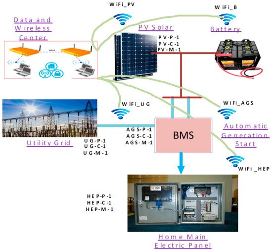
Figure 1. Battery Management System (BMS) connections and integrations [5].
2.1. Components and Topology
A BMS cannot be used as a standalone within a system infrastructure. It is integrated with other system modules to accomplish the system objectives. For example, an intelligent energy automation system includes a battery management module (BMM), battery interface module (BIM), battery units, and battery supervisory control. The system protects the battery pack, extends the battery lifetime, manages the power demand, and interfaces with the different network [13].
There are three implementation topologies—centralized, distributed, and modular —available in the BMS market. In a centralized topology, a single control unit and battery cells are put together through multiple wires. For distributed topology, each control unit is dedicated to each battery cell by a single communication cable. Lastly, in modular topology, multiple numbers of control units deal with a particular battery cell, but the control units are interconnected [14]. The centralized BMS is the most economical and least expandable. The distributed BMS is the costliest, but it is the easiest among the three to install and offers the cleanest assembly. The modular BMS includes more hardware and programming effort and makes a confrontation between the features and problems of the other two topologies. Figure 2 shows BMS implementation topology.
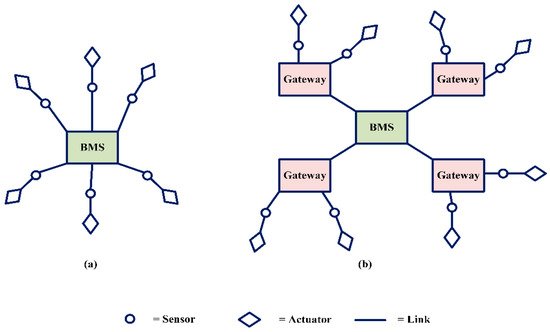
Figure 2. BMS implementation topology: (a) centralized, (b) distributed.
2.2. Software Architecture
BMS software architecture offers multi-tasking capabilities. Previously, it was not possible to continue different tasks simultaneously; one task was postponed to carry on the other task. Now, in new BMS software architecture, various tasks can be carried out together without any interruption. A BMS software architect’s initial tasks, such as voltage/current measurement, over current/voltage protection, temperature measurement, and protective relay actuation, must be performed promptly to ensure BMS safety. The real-time operating system (RTOS) is introduced in BMS software architecture to perform the real-time functionalities. Figure 3 shows the architecture of BMS software [15].
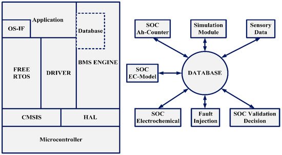
Figure 3. BMS software architecture.
2.3. Functionalities
BMS deals with battery packs that are connected internally or externally. It calculates the battery quantities, with typical measurements performed for cell voltages, pack current, pack voltage, and pack temperature. BMS uses these measurements to estimate state of charge (SOC), state of health (SOH), depth of discharge (DOD), and the operational key parameters of the cells/battery packs. The measurements also help to increase battery life and keep pace with the demand requirements of the original power network.
BMS is built using functional unit blocks and design techniques. Battery requirements for different applications will help to indicate the appropriate architecture, functional unit blocks, and related electronic circuitry to design a BMS and BMS charging scheme. Battery life can be optimized based on the following features [16]:
- ‒
-
Energy management system with a user interface to control and examine battery systems’ performance in different system blocks.
- ‒
-
Battery pack performance and safety features.
- ‒
-
Resiliency among the system units in different accident scenarios.
- ‒
-
Advanced technologies that integrate batteries with conventional/non-conventional energy sources.
- ‒
-
Internet-of-things (IoT), which monitors and controls the energy management system.
BMS will investigate the following significant capabilities and functions: automatic charging/discharging, protection, monitoring, and stability and resiliency. The following figure provides a functional tree of BMS.
Furthermore, BMS has efficient impacts related to accuracy and battery life. It leads to increased battery life with accurate operation measurements and control. BMS applies different methods for accurate modeling, which can provide a significant improvement in terms of the accuracy of the SOC estimation. Additionally, the accuracy of cell balancing is another benefit of BMS functions in the service of energy performance optimization. It is used to improve battery performance with proper measures within a system. BMS is able to control the power of the battery at its maximum efficiency with extended battery life. The system will protect the battery pack, extends the battery lifetime, manages the power demand, and interfaces with the different network.
On the scale of the accuracy, it calculates the battery quantities, with typical measurements performed for cell voltages, pack current, pack voltage, and pack temperature. BMS uses these measurements to estimate state of charge (SOC), state of health (SOH), depth of discharge (DOD), and the operational key parameters of the cells/battery packs. The measurements also help to increase battery life and keep pace with the demand requirements of the original power network.
Battery life can be optimized based on the energy management system with a user interface to control and examine battery systems’ performance in different system blocks. The charging and discharging management significantly impacts battery life. The economic advantages of BMS are extensions of battery lifetime, increasing the accuracy, and lowering the cost. Figure 4 shows the functions of BMS.
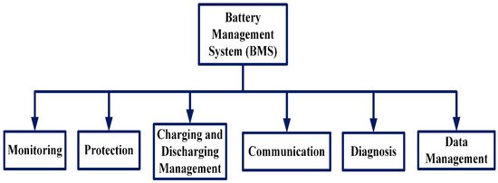
Figure 4. BMS functionalities.
BMS has significant impacts on batteries’ operation and performance, especially on reducing the environmental impact of battery systems. BMS can protect the battery system from external events since the battery pack’s external environment causes changes in the cell/pack parameters. Two types of temperatures—electrochemical reaction temperature and battery environment temperature—can be controlled in the battery pack for BMS safety. BMS can ensure control of these two types of battery temperatures within their safety limit. BMS is capable of handling the potential hazards related to the operation within battery systems. It allows protection of loss of air conditioning and battery cooling and protects the loss of battery heating controls (BSS).
Kokkotis et al. discussed the electrochemical means of EES systems such as batteries. The authors represented the caused damage to humans and the environment from batteries and other energy storage systems. The paper also covered a short review of the small-scale energy storage systems based on their environmental impacts. Besides, this paper explained the causes of soil and water pollution and endangered wildlife. Cadmium can cause damage to soil micro-organisms and affect the breakdown of organic matter. Other chemicals used in modern electrochemical batteries and any protective means of safe utilization with minimum environmental impact are also discussed in the paper [17].
A preparatory study on eco-design and energy labeling of rechargeable electrochemical batteries with internal storage under FWC ENER/C3/2015-619- Lot 1 is highlighted in [18]. It confirmed the European Union (EU) directives to describe the prospective boundaries or definitions to address the eco-design performance improvement. The main objective of requirements is to reduce the carbon footprint per functional unit modeled its projected useful lifetime. The standard IEC 62620 for industrial Li-ion batteries (from cell to system level) can be considered a valid base. The cycle-life test in IEC 62620 seems too different from the envisaged applications. In general, extending the lifetime of EV battery application by offering environmental and economic benefits reduces the need for primary resources. The criterion will create the conditions for more efficient management of batteries.
Moreover, BMS can control the charge and discharge cycles to avoid overloading the power and thermal impact that may reflect the environment. These actions can reduce the emissions from the power plants and the utility grids, which effectively reduces air pollution and enhances the human health measures and impacts.
Table 1 presents and summarizes the BMS issues on environmental impact, the efficiency, and the other operational parameters.
Table 1. BMS impacts.
| Environmental Impact | Technical Efficiency Impact |
|---|---|
| Reduction in CO2 emissions: Reduction in CO2 emissions by a rate of 40% is possible when a battery is controlled by BMS to store off-peak clean electricity to serve peak demand. |
Real-Time State of Health Estimation: BMS enables precisely to predict the state of health (SOH) of a battery. It has positive impact on the safety and quality of the operation and performance. |
| Greenhouse gas (GHG) benefits: The greenhouse gas (GHG) benefits of batteries could be doubled using BMS and better use of clean off-peak electricity. |
Optimal Charging: The target is less time-consuming, highly efficient, safer, and optimal solutions based on the design parameters. |
| Metal depletion impacts BMS can be efficient in controlling the charging/discharging cycles and the operation frequency. It impacts the comprised materials that have high environmental and energy impacts. |
Fast Characterization: BMS enables the SOC and SOH characterizations. SOC is modeled using one complete cycle of data, whereas SOH characterization is done based on the number of cycles of data. |
| Temperature control impacts Two types of temperatures—electrochemical reaction temperature and battery environment temperature—can be controlled in the battery pack by BMS. |
Self-Evaluation: BMS enables an evaluation based on mathematical models to represent the complex features of a battery, such as power, capacity, temperature effects, and hysteresis effects. |
2.3.1. Monitoring
BMS mainly focuses on monitoring the battery pack voltage, current, cell voltage, temperature, isolation, and interlocks. A faulty battery charging system or voltage regulator can cause overvoltage in the battery system. An overvoltage or overcurrent may cause permanent damage to the battery system, while the overcharge causes cell venting. As vented gases are flammable, it creates a severe safety concern. Similarly, a low voltage or current significantly affects battery performance. Isolation of the central battery system is an essential task for BMS, especially for a high voltage system. If a human body comes into contact with a faulty high voltage battery system, the current will flow through the body and cause death. Temperature control is another crucial task for BMS. High temperatures create heat and other abnormal issues that negatively impact the battery system [19].
2.3.2. Protection
A BMS must ensure protection against any battery system hazards. The BMS safeguard includes (among others) detecting the operating mode, setting fault criteria, authenticating, and identifying the system, predicting the pack/cell overvoltage and overcurrent, predicting the isolation fault, and detecting the high/low temperature. A BMS must protect the battery system from the external event since the external environment of the battery pack causes the changes in the cell/pack parameter.
2.3.3. Charging and Discharging Management
The state of charge (SOC) has a significant impact on battery life. Each battery has a specific number of charging and discharging cycles, and the battery life reduces with the increased number of charging and discharging phenomena. BMS must confirm the efficient way for charging and discharging procedures. Additionally, a BMS must maintain the proper SOC so that the battery lifetime will be maximized. To ensure management in this area, BMS performs the following tasks: control the charger current, turn on/off active switches between the pack and load/charger, run the pre-charge sequence, set dynamic power limits, and conduct active and passive balancing.
2.3.4. Diagnosis
BMS estimates and predicts the depth of discharge (DOD), state of charge (SOC), battery capacity, cell temperature, state of fitness (SOF), available energy, charging time, remaining useful life (RUL), remaining runtime, and the inner impedance of cell and current capability to ensure efficient battery performance. BMS is also responsible for detecting faults, such as fires, thermal runaways, explosions, and minimizing the consequences of fault effects. Therefore, fault diagnosis is an important functionality for BMS [11].
The DOD calculation is essential to estimate the effective battery cycle. Sometimes the higher DOD will reduce the battery lifetime. For example, lead-acid batteries show less lifetime if the DOD is more than 50%. So, the DOD should be maintained in BMS to avoid unexpected hazards. The SOC is an alternative form of the same DOD measurement. Battery capacity indicates the amount of energy that can be extracted from the battery. Typically, the battery capacity measures the stored charge (in ampere-hours). Battery capacity is related to cell temperature. Batteries perform best at room temperature. The decreased temperature raises the internal resistance of the battery, which decreases battery capacity. Whether excess heat or excess cold, both reduce the C-rate of the battery. Along with other testing, the SOF determines the capability of the battery to be matched with the system.
2.3.5. Components and Topology
The communications between internal and external BMS and between BMS and the primary system are vital for the battery system’s performance optimization. BMS can predict the battery’s future states and direct the main system to perform and prepare accordingly. Sometimes, its main system structure may need to change the working strategy according to the battery’s performance. In such a case, BMS is the only thing that can communicate with the main system and inform the predicted BMS results of the battery pack.
References
- “Energy Storage Safety Strategic Plan—December 2014,” Energy.gov. Available online: (accessed on 18 November 2020).
- Jiang, J.; Zhang, C. Fundamentals and Applications of Lithium-Ion Batteries in Electric Drive Vehicles; Wiley Online Library: Hoboken, NJ, USA, 2015.
- Pop, V. (Ed.) Battery Management Systems: Accurate State-of-Charge Indication for Battery Powered Applications; Springer: Dordrecht, The Netherlands, 2008.
- Sung, W.; Shin, C.B. Electrochemical model of a lithium-ion battery implemented into an automotive battery management system. Comput. Chem. Eng. 2015, 76, 87–97.
- Xing, Y.; Ma, E.W.M.; Tsui, K.L.; Pecht, M. Battery Management Systems in Electric and Hybrid Vehicles. Energies 2011, 4, 1840–1857.
- Lelie, M.; Braun, T.; Knips, M.; Nordmann, H.; Ringbeck, F.; Zappen, H.; Sauer, D.U. Battery Management System Hardware Concepts: An Overview. Appl. Sci. 2018, 8, 534.
- Luo, X.; Kang, L.; Lu, C.; Linghu, J.; Lin, H.; Hu, B. An Enhanced Multicell-to-Multicell Battery Equalizer Based on Bipolar-Resonant LC Converter. Electronics 2021, 10, 293.
- Aiello, O. Electromagnetic Susceptibility of Battery Management Systems’ ICs for Electric Vehicles: Experimental Study. Electronics 2020, 9, 510.
- Ko, Y.; Choi, W. A New SOC Estimation for LFP Batteries: Application in a 10 Ah Cell (HW 38120 L/S) as a Hysteresis Case Study. Electronics 2021, 10, 705.
- Doridant, A.; Abouda, K.; Givelin, P.; Thibaud, B. Battery Management System Demonstrator Board design using EMC System simulation. In Proceedings of the 2019 International Symposium on Electromagnetic Compatibility—EMC EUROPE, Barcelona, Spain, 2–6 September 2019; pp. 427–432.
- Aiello, O.; Crovetti, P.S.; Fiori, F. Susceptibility to EMI of a Battery Management System IC for electric vehicles. In Proceedings of the 2015 IEEE International Symposium on Electromagnetic Compatibility (EMC), Dresden, Germany, 16–22 August 2015; pp. 749–754.
- Kang, T.; Park, S.; Lee, P.-Y.; Cho, I.-H.; Yoo, K.; Kim, J. Thermal Analysis of a Parallel-Configured Battery Pack (1S18P) Using 21700 Cells for a Battery-Powered Train. Electronics 2020, 9, 447.
- Abbas, M.; Cho, I.; Kim, J. Analysis of High-Power Charging Limitations of a Battery in a Hybrid Railway System. Electronics 2020, 9, 212.
- Arnieri, E.; Boccia, L.; Amoroso, F.; Amendola, G.; Cappuccino, G. Improved Efficiency Management Strategy for Battery-Based Energy Storage Systems. Electronics 2019, 8, 1459.
- Lee, S.; Kim, J. Power Capability Analysis of Lithium Battery and Supercapacitor by Pulse Duration. Electronics 2019, 8, 1395.
- Uno, M.; Ueno, T.; Yoshino, K. Cell Voltage Equalizer Using a Selective Voltage Multiplier with a Reduced Selection Switch Count for Series-Connected Energy Storage Cells. Electronics 2019, 8, 1303.
- Kokkotis, P.I.; Psomopoulos, C.S.; Ioannidis, G.C.; Kaminaris, S.D. Small Scale Energy Storage Systems. A Shot review in their Potential environmental impact. Fresenius Environ. Bull. J. 2017, 26, 5658–5665.
- Van Tichelen, P.; Mulder, G.; Durand, A. Preparatory Study on Ecodesign and Energy Labelling of Rechargeable Electrochemical Batteries with Internal Storage under FWC ENER/C3/2015-619-Lot 1, TASK 7 Report Policy Scenario Analysis VITO, Fraunhofer, Viegand Maagøe. Available online: (accessed on 18 November 2018).
- Lee, H.; Park, J.; Kim, J. Kim Incremental Capacity Curve Peak Points-Based Regression Analysis for the State-of-Health Prediction of a Retired LiNiCoAlO2 Series/Parallel Configured Battery Pack. Electronics 2019, 8, 1118.


