 +1 credit
| Version | Summary | Created by | Modification | Content Size | Created at | Operation |
|---|---|---|---|---|---|---|
| 1 | Weiwen Zhang | + 1252 word(s) | 1252 | 2020-04-16 07:58:29 | | | |
| 2 | Catherine Yang | Meta information modification | 1252 | 2020-04-17 03:47:14 | | |
Video Upload Options
One of the most recent manifestations of avionics system is Distributed Integrated Modular Avionics (DIMA). The study of DIMA architecture is essential when considering two levels of mappings, that is (1) software modules to hardware components, and (2) hardware components to installation locations. This entry describes the hierarchical design of DIMA, including system layer, hardware layer and installation layer that are linked with a group of constraints and quality measures.
Understanding system architecture of DIMA is essential for optimizing the system. Figure 1 illustrates the overall architecture of DIMA system, with the consideration of the hardware and software mapping and its quality measures as well as constraints. It has a hierarchical layer design for allocation, which includes system layer, hardware layer, and installation layer. The subsystems in the system layer are supported by the hardware in the hardware layer, with functions mapped into devices and signals into links. The hardware in the hardware layer is installed into the installation layer, by placing devices into mount locations and connecting cables via networks.
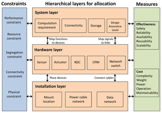
Figure 1. System architecture of DIMA. The design of system layer, hardware layer and installation layer is linked with a group of constraints and quality measures.
System Layer
The system layer describes the functional subsystems. From the perspective of system design, each subsystem has its own specifications, including resource requirements (i.e., computation and storage), connectivity requirements, specific capacity and other properties of relevance for the DIMA architecture design such as their Design Assurance Level (DAL) or specific hardware dependencies. As shown in Figure 2, DIMA system is broken down into a hierarchical tree of subsystems, with the root node representing the entire system[1]. Typical subsystems in the aircraft can be Bleed-Air System (BAS), Overheat Detection System (OHDS), Pneumatic System (PS) and Ventilation Control System (VCS)[2]. The purpose of this layer is to capture the system logic, tasks and connections, as well as peripherals and interfaces for functional subsystems.
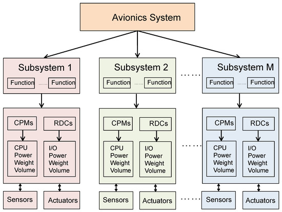
Figure 2. The structure of system layer in DIMA. The system layer contains multiple subsystems[1].
Each of the subsystems in the system layer is composed of functions from an architectural point of view. Such an abstraction in form of functions is beneficial to reduce the complexity of the system. Typical functions of the aircraft include but are not limited to: aileron control, multi-function spoilers control, ground spoilers control, rudder control and brake function. For example, an aileron controller function is in charge of monitoring and actuating flight control surfaces. It may consist of a sensor acquisition module, a monitor module, and an actuator controller module. These modules are enabled by a set of hardware components in the hardware layer, including CPMs, RDCs and sensors.
Hardware Layer
The hardware layer contains hardware devices, their configurations, and network topology, which support the functions in the system layer. The main categories of DIMA devices are sensors, actuators, cables, switches, Core Processing Modules (CPMs), Remote Data Concentrators (RDCs), and Input/Output (I/O). The purpose of these devices is to provide the necessary resources (computing power, memory, data storage, etc.) to the system. Each device is characterized by its type (Central Processing Units (CPUs), network hardware, or peripherals), vendor, weight, volume, power, input ports, output ports and supported signal types. Such characteristics are important in designing the quality measures and constraints in the optimization problem. The details of the DIMA devices are as follows.
Sensor/Actuator
Sensors and actuators are peripherals that sense and control the physical airplane. Sensors perform data acquisition including position, pressure, temperature and other readings. Actuators manipulate various control surfaces and other systems such as cabin pressure or landing gear.
Core Processing Module
CPM provides computation resources and storage for the tasks on the DIMA system. Core Processor Input/Output Module (CPIOM) is a variant that provides a combination of compute resources, input and output ports for distributed data pre-processing or tightly coupled control loops. By using CPIOMs, one may ease the need for high-speed field buses or dedicated I/O communication devices. However, the disadvantage of such I/O integration may come at the increasing number of different CPIOMs required for specific needs [3].
Input/Output
I/O devices allow data conversion and communication to external devices outside the DIMA system, which are not compatible with the internal network. Usually, these are sensors (providing inputs) and actuators (requiring outputs) that interface the DIMA system. The I/O interface can be integrated or separated from CPMs. The integration of application processing and I/O functions is enabled by CPIOM, while their physical separation is enabled by the concept of Distributed Modular Electronics (DME).
Network
Processing components and I/O handling components exchange signals and communicate through Avionics Data Communication Network (ADCN) [4]. ADCN is based on Avionics Full-Duplex Switched Ethernet (AFDX) with a switched star topology [5], which is a standard protocol in DIMA architecture. The central concept of AFDX networks is Virtual Link (VL), which designates the flow of information between functions. A VL is an unidirectional logic path connecting the source to all of the destination end-systems with only switches as intermediate nodes in the path. From a graphical point of view, it consists of paths from the source node to each of the terminal nodes. Switches and cables are the backbone of AFDX network hosting the communications between CPMs and other devices connected to the network. AFDX messages between functions are realized by connection of cables between devices located in different cabinets.
Remote Data Concentrator
Remote Data Concentrator (RDC) connects sensors and actuators through ADCN with CPMs. RDC is usually placed near sensors and actuators so that fewer cables are needed. It translates signals between different protocols such as Controller Area Network (CAN) and Inter-Integrated Circuit (I2C) of peripherals.
Installation Layer
The installation layer describes hardware allocation to the anatomy of underlying aircraft. It is powered by mount locations and power network.
Hardware devices can be installed at different mount locations of the aircraft, such as cockpit, avionics bay, middle, tail, and so forth. The installation location is characterized by its coordinates, volume, cooling capacity, power supply, number of slots and mass. The location characteristics should be considered for the optimization on installation of devices. While placement of some components are fixed (e.g. sensors and actuators), CPMs placement and cable routing are needed to determine for the optimization subject to constraints, such as physical and safety requirements.
The power network enables the mount locations to be connected with tunnels, which provides power for the devices installed at the location. Such a network is different from the one in the hardware layer that represents communication network among the devices.
These three layers are interconnected via hardware and software mapping in the DIMA system. Particularly, the hardware and software mapping can include the followings:
(1) Device assignment: it maps devices to locations in the aircraft. The assignment should consider connectivity and physical constraints.
(2) Task assignment: it maps tasks to devices. The assignment should consider resource and segregation constraints.
(3) Link assignment: it maps cable routes for links to connect devices. The assignment should consider connectivity and resource constraints,
(4) Signal assignment: it maps signals to links when tasks, devices, and links are assigned. The assignment should consider segregation and resource constraints.
Hardware and software mapping on different functional layers aims to optimize a set of quality measuresforDIMAsystems. Meanwhile,the optimization requires to satisfy agroup of the constraints due to resource limitation, inherent aircraft architecture and performance requirements [6][7]. Such a DIMA optimization problem is commonly formulated by Integer Linear Program (ILP) [8]. More details can be found in the published paper.
References
- Guoqing Wang; Qingfan Gu; Research on Distributed Integrated Modular Avionics system architecture design and implementation. 2013 IEEE/AIAA 32nd Digital Avionics Systems Conference 2013, DASC, 7D6-1-7D6-10, 10.1109/dasc.2013.6712647.
- Björn Annighöfer; F. Thielecke; A systems architecting framework for optimal distributed integrated modular avionics architectures. CEAS Aeronautical Journal 2015, 6, 485-496, 10.1007/s13272-015-0156-1.
- Rudolf Fuchsen; Preparing the next generation of IMA: A new technology for the scarlett program. 2009 IEEE/AIAA 28th Digital Avionics Systems Conference 2009, DASC, 7.B.5-1-7.B.5-8, 10.1109/dasc.2009.5347424.
- Thanikesavan Sivanthi; Shu Zhang; Ulrich Killat; A holistic framework for optimal avionics system resource planning, 2007 Workshop on Aicraft System Technologies, 2007, 257-268.
- Jean-Bernard Itier; A380 integrated modular avionics; Proceedings of the ARTIST2 meeting on integrated modular avionics, 1, No. 2, 2007, 72-75.
- Pierre Bieber; Jean-Paul Bodeveix; Charles Castel; David Doose; Mamoun Filali; Frederic Minot; Cedric Pralet ; Constraint-based design of avionics platform-preliminary design exploration; 4th European Congress ERTS Embedded Real Time Software, 2008.
- Laurent Sagaspe; P. Bieber; Constraint-based design and allocation of shared avionics resources. 2007 IEEE/AIAA 26th Digital Avionics Systems Conference 2007, DASC, 2.A.5-1-2.A.5-10, 10.1109/dasc.2007.4391846.
- Björn Annighöfer; Ernst Kleemann; Frank Thielecke; Automated selection, sizing, and mapping of integrated modular avionics modules. 2013 IEEE/AIAA 32nd Digital Avionics Systems Conference (DASC) 2013, DASC, 1-22, 10.1109/dasc.2013.6719627.


