 +1 credit
| Version | Summary | Created by | Modification | Content Size | Created at | Operation |
|---|---|---|---|---|---|---|
| 1 | Blesson Isaac | + 16242 word(s) | 16242 | 2021-01-12 07:00:27 | | | |
| 2 | Karina Chen | -12039 word(s) | 4203 | 2021-01-15 09:24:14 | | | | |
| 3 | Karina Chen | Meta information modification | 4203 | 2021-01-20 07:28:41 | | |
Video Upload Options
Relative to many other nanofiber formation techniques, the electrospinning technique exhibits superior nanofiber formation when considering cost and manufacturing complexity for many situations. Aligned electrospun nanofibers have applications in nanocomposite structures and energy storage devices in addition to applications like air filtration, desalination, tissue engineering, textiles etc. The specific strength and dielectric constant are important to understand mechanical and dielectric properties of electrospun fibers and tailor these properties in the field of composite and energy applications.
1. Introduction
Many advanced applications can benefit from electrospun materials with superior mechanical and dielectric properties, especially in the fields of composite reinforcement and energy. Aligned electrospun fibers, more specifically, have applications in structural reinforcement of materials and energy storage devices. For these applications, it is paramount to understand the effects of electrospun fiber alignment on mechanical and dielectric properties. Though adding appropriate fillers to the polymers changes mechanical and dielectric properties, better fiber alignment alone improves these properties and keeps the composition uniform throughout. Mechanical and dielectric properties depend on the density and porosity of nanofiber mats, as well as the fiber morphology, including the fiber diameter, and the effect of degree of alignment [1][2][3]. Therefore, it is necessary to understand the knowledge on both mechanical and dielectric properties of polymer mats together. Mechanical and dielectric properties are among the most important parameters to determine the performance of the polymeric nanomaterials [4][5]. Electrospinning influences both mechanical and dielectric properties of nanofiber membranes [4]. Electrospinning is the process of producing micro- and nanofibers, using a polymer solution with a syringe pump, syringe, needle, collector, and high-voltage power supply. The typical setup of an electrospinning apparatus is either horizontal electrospinning or vertical electrospinning [6]. Figure 1 shows the schematic setup of both types.
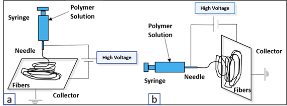
Figure 1. (a) Schematics of electrospinning apparatus of vertical setup and (b) horizontal setup.
1.1. History of Electrospinning
The idea of electrospinning can be traced back to 1900, when John. F Cooley received the patent for his apparatus for electrically separating the relatively volatile liquid component from the component of relatively fixed substances of composites [7]. Later in 1902, John F. Cooley invented an apparatus for electrically dispersing fluids [8] and William James Morton invented methods of dispersing fluids by the process of separating the volatile components and breaking up the fixed component from composite fluids [9]. Anton Formhals received a patent in the year 1934 for his invention of producing polymer threads, using electrostatic force. In his paper titled “Process and apparatus for preparing artificial threads” [10], solutions of cellulose esters, specifically cellulose acetate were used for spinning. In US Patent No. 2,160,962 (1939), artificial fibers were collected as substantially parallel to each other on a moving collecting device [11]. There he introduced the term “electrical spinning” of fibers. In the spinning process there were difficulties in solidifying the formed fibers. In addition, the as-processed fibers were so sticky that, not only would they stick to the collecting device, but also they would stick to each other. He observed that it was difficult to control the paths of high-speed liquid streams and the corresponding fibers out of it. As shown in Figure 2, fiber direction guide (55 in Figure 2), which consists of shields (57 in Figure 2) to direct the fibers along fixed, predetermined paths toward the collecting electrodes was used. This invention made it possible to obtain smooth, continuous, compact, and coherent fiber bands composed of heterogeneous filaments arranged substantially parallel to each other.
Zhang et al. (2016) reported that different nanofiber production methods include vapor growth, arc discharge, laser ablation, and chemical vapor deposition [12]. These processes are very expensive because of low product yield and high equipment cost. However, electrospinning employs a top-down engineering approach, which can produce fibers with diameters ranging from 10 nm to 10 µm, from a polymer solution, under the application of an electrostatic force [13][14]. These fibers have a high surface area to volume ratio, high porosity, and tunable porosity [6]. According to Luo et al. (2012), there are various spinning techniques available for producing micro and nanofibers [14]. Solution electrospinning compared to melt electrospinning requires a solvent. The melt electrospinning method uses a molten polymer, but the absence of solvent excludes the effect of solvent properties on the fiber formation. In emulsion electrospinning, two immiscible fluids are used as in food-processing [15]. Magnetic electrospinning and near-field electrospinning are good examples of interdisciplinary technological convergence between magnetism and electric potential methods. Dip-pen nanolithography with traditional electrospinning can also be used, but the alignment of fibers is not satisfactory [14].
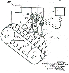
Figure 2. Electrospinning setup by A. Formhals [11].
1.2. Working Principle of Electrospinning
The working principle for electrospinning is shown in the Figure 3. A sufficiently high voltage is applied at the location of the liquid droplets formed at the tip of the needle. The local body of the liquid becomes charged. Electrostatic repulsion counteracts the surface tension. Thus, the droplet is stretched, and at a critical point, a stream of liquid erupts from the surface. The point of eruption is called a Taylor Cone. Sir Geoffrey Taylor developed the equation which shows the relationship between the critical voltage and the surface tension as shown in Equation (1) [16][17].
|
|
(1) |
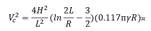
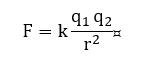
where is the critical voltage, H is distance between the needle tip and the collector, L is the length of the needle with radius R, and is the surface tension of the liquid (units: in kilovolts; H, L, and R in cm; and in dyne per cm). Afshari (2017) showed that electrostatic forces play a key role on the electrospinning of polymer solutions [18]. As such, the Coulomb’s force is considered as the driving factor for better design. In Equation (2) shown below, F is the Coulomb’s force, is the constant of proportionality, are charges, and r is the distance between the charges. In principle, the smaller the distance, the greater the electrostatic force on a charged particle.
|
|
(2) |
When an electric field is applied, the liquid jet ejected from the tip of the nozzle/needle travels on a straight line for a short distance. The diameter of the jet, in the straight line, decreases monotonically with the distance from tip, after that a radially outward bending instability happens. The electrostatic force from the charge carries with the jet causes the jet to continue to elongate as it coils and the thin fluid jet solidifies into nanofiber [19].
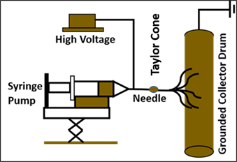
Figure 3. Working principle of electrospinning.
1.3. Applications of Electrospun Fibers
The typical applications of electrospun fibers include filtration, energy, structures, biomedical, textiles, and others [4] as shown in Figure 4. Other applications include optical and chemical sensors, textiles, reinforcement of composites, health care, and defense and security. Electrospun fibers are projected to play an important role in the development of air filtration, energy storage devices, super-capacitors, and rechargeable batteries [20][21][22][23][24][25][26].
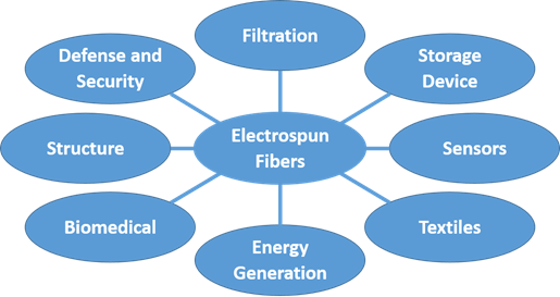
Figure 4. Applications of electrospun nanofibers.
The applications of nanofiber mats in the reinforcement of nanocomposites are discussed by Huang et al. (2003), who executed mechanical characterization of nanofibrous membranes of various polymers and examined their potential applications [17]. Nanofibers can have better mechanical properties than microfibers and therefore superior structural properties can be anticipated. Jiang et al. (2018) provided an overview of nanofiber composite application [27]. Bergshoef and Vancso (1999) showed that smooth nylon-4, six electrospun fibers with diameters in the range of 30–200 nm can be produced from formic acid solutions. These fibers demonstrated reinforcement of transparent composites with an epoxy matrix [28]. Highly porous nanofibers with pore interconnectivity and relatively uniform pore distributions improve membrane performance in the application of desalination (water filtration) [29]. The large surface area of the constituent fibers provides high functionalization capability and mechanical bonding to limit delamination between laminae [30]. Biomedical applications include tissue engineering scaffolds, wound dressing, drug delivery [31], and creation of artificial blood vessels. The non-woven nanofibrous mats produced by electrospinning techniques mimic the extracellular matrix components.
1.4. Recent Review Papers on Electrospun Nanofiber
Table 1 lists twelve recent review papers on electrospun fiber applications and characterizations. Of the papers considered, reviews of applications dominate the literature, are a few on mechanical, energy, medical, and processing characterizations. However, there is little work found in the literature on dielectric and mechanical properties together that should contribute to both composite reinforcement and energy applications.
[32]Table 1. Recent review papers on electrospun nanofibers.
| Authors | Year | Main Criteria of Review Papers |
|---|---|---|
| Huang et al. | 2003 | Processing, structure, characterization, applications, modeling and simulation, and different polymers in solution and melt form [17] |
| Pham et al. | 2006 | Tissue engineering (scaffolds) [32] |
| Bhardwaj and Kundu | 2010 | Polymers, parameters, melt electrospinning, and applications [6] |
| Luo et al. | 2012 | Scale-up challenges and applications [14] |
| Shuakat et al. | 2014 | Nanofiber yarns and nanofiber alignment [33] |
| Shi et al. | 2015 | 1D nanomaterials have high surface-area-to-volume (specific surface area), high aspect ratio, and high pore volume. Well-aligned and highly ordered are suitable for energy harvesting and storage devices. More advantageous than conventional materials [34] |
| Ahmed et al. | 2015 | Desalination [35] |
| Zhang et al. | 2016 | Energy storage [12] |
| Peng et al. | 2016 | Tissue regeneration, energy conversion and storage, and water treatment [23] |
| Shekh et al. | 2017 | Water purification [36] |
| Zhang et al. | 2018 | Food packaging [15] |
| Li et al. | 2019 | Electrical and mechanical performance of polymer nanocomposites [37] |
1.5. Parameters and Parameter Optimizations
Important parameters that affect the quality of electrospun fibers formed from polymer solutions can be categorized as solution-specific parameters, process-specific parameters, and environmental-specific parameters [6][17][38].
-
(a)
-
Solution parameters: The solution-specific parameters include viscosity, polymer concentration, surface tension, conductivity, and evaporation rate of solvent [18][39][40][41][42][43]. It is observed that low viscosity is typically responsible for bead generation and significant increase in fiber diameter. A similar conclusion was made on polyacrylonitrile/dimethylformamide (PAN/DMF) solution where beads were easier to form at low concentration of 5 wt.% than that formed at higher concentration of 7 wt.% [44][45]. Typically, viscosity and concentration are directly proportional to each other [46]. Additionally, polymer concentration directly controls fiber diameter [46]. In general, an increase in fiber diameter can be achieved by increasing the polymer concentration. Higher surface tension causes bead formation and reduced surface tension favors smooth fiber formation [47].
-
(b)
-
Process parameters: Applied voltage, distance between the nozzle tip and collector, rotating speed of the collector (if drum is used), and solution feed rate are the parameters that are regarded as process specific [48][49][50]. In general, fiber diameter can be reduced by increasing applied voltage and vice versa. If the applied voltage reaches a critical value, a charged jet initiates the electrospinning process. This critical voltage is closely related to surface tension of the solution. Lee et al. (2003) reported that there was a linear relationship between voltage applied and surface tension of polystyrene (PS) dissolved in a mixture of tetrahydofuran and DMF [51]. The distance between the tip and the collector mainly controls fiber solidification because a minimum distance is required to allow the fibers sufficient time to dry before reaching the collector. Distances that are too close or too far can cause beads to form. Fang et al. (2010) studied 7 wt.% PAN/DMF electrospun at 2–10 cm away from nozzle tip. The experiments concluded that beads were producing until the distance reached 7 cm [52]. Longer distance between nozzle tip and collector produced bead free fibers.
-
(c)
-
Environmental parameters: Humidity and temperature are treated as environment-specific parameters [53][54]. According to De Vrieze et al. (2009), the evaporation rate increases with increase in temperature [55]. Moreover, the viscosity of solution generally decreases with an increase in temperature. As the humidity increases, the average fiber diameter increases.
Parameter optimization: Formation of nanofibers involve many input parameters, as mentioned above, to evaluate outputs such as fiber diameter, tensile strength, modulus, and dielectric properties of nanofibers. Parameter optimization helps to achieve desired outputs by tailoring the input parameters. One among the many mathematical modeling techniques for parameter optimization is Design of Experiment (DoE), which is an approach that helps to find the relationship between different inputs over outputs. Parameter optimization based on applied voltage and concentration has been studied by using the DoE approach by Gu et al. (2005) [56]. The study concluded that concentration of solution played an important role to the diameter of nanofibers. Gu et al. (2005) used two factors and four and three respective levels for finding average fiber diameter. Senthil and Anandhan (2005) examined three variables and seven, four, and three respective factor levels for finding the average fiber diameter [57]. Isaac et al. (2018) used DoE approach with two factors and three levels for optimizing the two outputs, namely, specific dielectric constant and specific mechanical strength [58][59]. A mathematical modeling, including the leaky dielectric model which describes the deformation of a Newtonian drop in an electric field and whipping model which depicts the interaction between the electric field and fluid properties for electrospinning processes, has been portrayed by Rafiei et al. (2013) [60]. Ismail et al. (2016) developed a model for stable region and unstable region in the jet propulsion stream for predicting the fiber diameter [61]. Rafiei et al. (2014) modeled and simulated viscoelastic elements for jet propulsion to predict and improve control of nanofiber diameter [62]. Modeling electrospinning of nanofibers for short-range and long-range electrostatic interactions, using a discrete slender model, was conducted by Kowalewski et al. (2009) [63]. The whipping instability in the unstable region of the electrospinning jet propagation has been studied in three polymeric solutions by Kowalewski et al. (2005) [64]. The fiber gets stretched into fractions of initial diameter at the instability region. Ghaly (2014) modeled the electrospinning jet with an inkjet printer technique, using computer-aided fluid/multi-physics/multi-phase flow simulations in COMSOL multiphysics software [65].
2. Molecular Orientation and System Configurations of Nanofibers
Two key factors affecting mechanical and dielectric properties are (a) molecular orientation due to elongation of fibers on the periphery of the rotating mandrel [66] and (b) system configuration improvement for obtaining improved properties due to better alignment [67]. Other properties, such as thermal and electrical properties [68] are also often improved by alignment.
2.1. Molecular Orientation of Nanofibers
High orientation of polymer molecular chains along the fiber axis and aligned electrospun fibers have important consequences in the field of carbon fiber-reinforced nanocomposites. The electrospun fibers are generally stronger than traditional fibers because of their higher orientation of macromolecular polymer chains along the fiber axis. The polymer jet under the influence of an electrostatic field experiences a high degree of molecular orientation due to high elongation strains and shear forces. As explained later, in Section 2.2, System Configuration to Align Fibers, optimal speed of fiber collecting drum brings about better alignment. In addition, optimal speed of collecting drum causes maximum molecular orientation. Beyond the optimal speed, the orientation can decrease slightly. According to Fennessey and Farris (2004), twisted yarns of higher degree of molecular orientation resulted in better mechanical properties [67]. The degree of orientation can be quantified by the X-ray diffraction analysis of the samples. The nitrile group in PAN is oriented in approximately perpendicular to the draw direction. The absorbance of perpendicular polarization showed nitrile-stretching vibration with strong dichroism, and therefore better orientation. A twist angle of 11° in as-spun PAN fiber improved the initial modulus and ultimate strength of 2.6 GPa and 56 MPa, respectively, to 2.2 times and 2.9 times, respectively. Molecular orientation results in better mechanical properties in general, Young’s modulus in particular, of the resulting carbon fibers [69][70]. Baji et al. (2010) studied the effects of electrospun polymers on oriented morphology and tensile properties. The lower the diameter of the fibers, the higher the modulus and strength of the fibers. They observed that finer fibers have enhanced properties because of gradual ordering of molecular chains and increase in crystallinity [71]. Baji et al. (2010) noticed that the modulus and tensile properties of polycaprolactone (PCL) fibers increased significantly when the fiber diameter was reduced to below 500 nm. The molecular orientation improves gradually as the fiber diameter is reduced. Moreover, Beese et al. (2013) concluded that electrospun PAN fibers have better mechanical properties at lower diameters [72]. Arshad et al. (2011) observed that the strength of the carbonized nanofibers at 800 °C increased by 100% when the diameter was reduced from 800 to 200 nm [73]. For composite applications, a decrease in diameter of fiber at the nanoscale level can improve mechanical properties as the specific reinforcement area per unit mass increases. Uyar et al. (2009) observed self-aligned bundled fibers of polyphenylene-g-polystyrene/poly (a-caprolactone) (PP-g-PS/PCL) when blended with polystyrene (PS) or polymethyl methacrylate (PMMA). This is because of the unique molecular architecture of PP-g-PS/PCL and its interaction with PS or PMMA [74].
2.2. System Configuration to Align Fibers
In addition to molecular orientation, physical alignment of electrospun fibers contributes to the production of high strength/high toughness fiber reinforced composites [12]. Among the many ways to produce aligned fibers by using an electrospinning technique, drum collection and rotating disk collectors are the two most popular designs, as shown in Figure 5a,b [75][76][77][78][79].
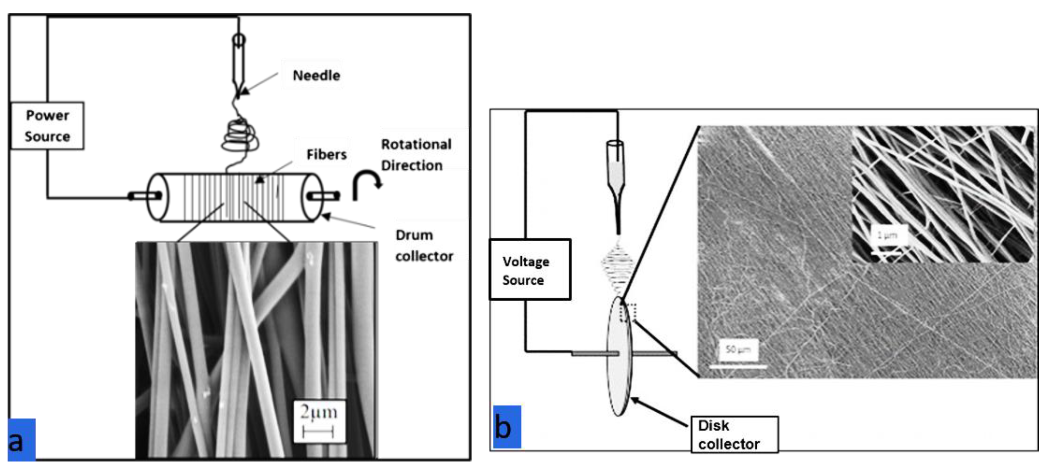
Figure 5. (a) Rotating drum collector. (b) Rotating disk collector [103].
In the drum collector method, the drum collector rotates at high speed and the deposited fiber diameter can be controlled based on the rotational speed of the drum [80][81][82]. The linear speed at the surface of the rotational drum should match the evaporation rate of the solvent so that fibers are deposited and taken up on the surface of the drum. At a rotational speed less than the fiber take-up speed, randomly oriented fibers are obtained on the drum. At higher speed, the fiber take-up velocity breaks the fiber, and continuous fibers are not collected. Therefore, the optimal speed of the rotating drum that matches the evaporation rate is required for maximum alignment [83].
In the rotating disk collector, higher alignment is possible but the production rate is lower because fibers are effectively deposited at only a small area at the disk edge. Theron et al. (2001) reported a conical and an inverted conical instability region of polyethylene-based polymer nanofibers. These finer fibers with diameters ranging from 100 to 300 nm got aligned and wound on a sharp edge disk wheel-like bobbin [16].
Other collection methods that are suitable for fiber alignment are the parallel conductor method, the wire drum collector method, and the wheel rotor collector method as shown in Figure 6a–d. In the parallel conductor method [84][85][86][87], the length of aligned fibers is restricted by the distance between conductive stripes as shown in Figure 6a. Jalali et al. (2006) reported the fundamental parameters affecting the uniaxially aligned PAN nanofibers. The best alignment of nanofibers with a specific gap distance depends on concentration, voltage, and tip to collector distance. As shown in Figure 6b, a bundle collector is moved across the gap to another side for depositing bundle of nanofibers. The best alignment was formed between 10 and 15 wt.% solutions. Uniaxially aligned fibers formed had an aspect ratio (l/d) of higher than 5000 and these fibers are useful in composite reinforcement application. Fryer et al. (2018) studied the effect of alignment on fiber modulus, using the electrostatic gap method. Aligned polyethylene oxide (PEO) fibers have a higher modulus than the non-aligned fibers of similar diameter [88]. Cai et al. (2017) provided an insight in to fabricating ultra-long polyvinylidene fluoride (PVDF) fibers. Here, parallel conducting U-shaped collectors are used to fabricate fibers [89]. According to Lei et al. (2018), more than a meter long aligned PVDF nanofibers were fabricated by using gap electrospinning, where the needle is connected to positive power supply and the parallel plates are connected to the negative power supply [90]. Yang et al. (2007) demonstrated a method that generates parallel fibers, using magnetic-particle-doped polymers in two parallel placed magnets. The magnetic field guides the magnetized electrospun polyvinyl alcohol (PVA) fibers to align in a parallel fashion [91]. Park and Yang (2011) built uniaxial aligned PCL fibers by introducing an inclined gap into dual collectors that consisted of two conductive stripes which were arranged vertically and horizontally [92]. Dabirian et al. (2009) used a hollow metallic cylinder with needle placed at the center of the cylinder. Fibers produced by this method are claimed to be well aligned and spread over large area [93]. Next, in the wire drum collector method, shown in Figure 6c, fibers are deposited without the need for high speed rotation [93]. However, aligned thick films are not possible with this method. Finally, a wheel rotor collector, as shown in Figure 6d, provides elongation strain and therefore more strength to the fibers. However, the many electrodes on the rotating wheel complicate apparatus design [94]. The limitations of other methods imply that drum collection is more likely to be scalable to commercial capacities than other electrospinning methods for fiber alignment. Despite the simplicity of the electrospinning methodologies, industrial applications are relatively rare due to low fiber throughput for existing fiber collection methods. This throughput limitation could be addressed with larger drum sizes and other innovations.
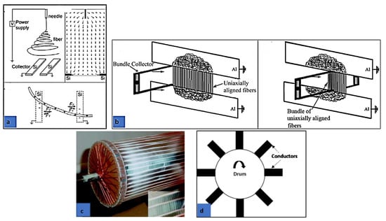
Figure 6. (a) Parallel conductor stripes method (reprinted with permission from Reference [95]. Copyright (2003) American Chemical Society). (b) Uniaxially aligned nanofibers [96]. (c) Wire drum collector (reprinted with permission from Reference [97]. Copyright (2004) American Chemical Society). (d) Wheel rotor collector.
In addition to the design methods mentioned above, there a few unconventional design configurations for aligning fibers. Grasl et al. (2013) developed a technique, using two parallel rotatable auxiliary electrodes applied with time-varying square wave potential, which led to aligned fiber-deposition of PEO [98]. Lei et al. (2017) used a collecting system consisting of insulating hollow cylinder and grating-like electrodes for aligning PVDF fibers, using whipping instability [98]. Khamforoush and Mahjob (2011) used a modified rotating jet method for aligning fibers. The degree of alignment enhanced by more than two times and the average amount of produced fiber is 40% more than that of the simple rotating jet method [99][100].
3. Applications of Aligned Fibers
The authors of this paper, Isaac et al. (2017), observed improvements in the mechanical strength and dielectric strength with increase in degree of alignment of fibers [101]. Aligned fibers are greatly beneficial when they are used in applications including field effect transistors, gas and optical sensors, fiber reinforced composite materials, and tissue engineering [102][103]. Bashur (2009) discussed the application of aligned fibers in the field of tissue engineering [104]. Moreover, Lawrence and Liu (2006) and Katti et al. (2004) stated that there are other applications found in the variety of areas if the fibers are in aligned form [105][106]. This section discusses mechanical and dielectric applications of aligned electrospun fibers.
3.1. Influence of Aligned Fibers on Mechanical Properties of Nanofiber Mats
Hou et al. (2005) showed that well-aligned, multi-walled carbon nanotubes (MWCNT) can improve the mechanical properties of a PAN-based nanofiber mat [107]. Kannan et al. (2007) demonstrated that electrospun polymer/CNT leads to nanocomposite fibers with embedded CNTs orienting parallel to the nanofiber axis [108]. Moreover, alignment of CNTs in the fiber direction can improve thermal conductivity [109]. Dhakate et al. (2016) reported that semi-aligned electrospun carbon nanofiber composites show excellent bending strength and interlaminar shear strength [110]. High-performance aramid copolymer fibers underwent four treatment factors. Among them, the degree of stretching after coagulation resulted in high degree of molecular orientation. The increased tensile strength of aramid fibers improved the cut resistance of aramid fibers, and therefore can be used in cut protection [111]. Ultra-high molecular weight polyethylene fibers with the tensile strength of 1.5 GPa were successfully prepared and structure and tensile property were studied. The increase in draw ratio improved the crystallinity of ultra high molecular weight polyethylene fibers. The molecular orientation degree increased, and tensile property also improved [112]. Increasing the draw-ratio resulted in an increased molecular orientation, Young’s modulus, and tensile strength of poly(amide-block-aramid) fibers comprised of alternating rigid aramid blocks of poly(p-phenylene terephthalamide) (PPTA) and flexible blocks of polyamide 6,6. Heat treatment at 300 °C of the fibers resulted in an increase of Young’s modulus and minor increase of strength [113].
Aligned micro scale fibers (7µm diameter) have application in composite reinforcement. There is increased need to manufacture complex composites for light weight applications. Carbon/epoxy composites have greater application in aircraft, sports cars,[114] and space crafts because of a better strength to weight ratio than that of metals like aluminum alloys. They are thermally stable because of the lower coefficients of thermal expansion properties of carbon fibers. Yu et al. (2014) showed that short carbon fiber composites can be used in places where complex shapes and ductile properties are required [115]. Short carbon fibers, with an aspect ratio of 400, resulted in composites with a tensile modulus of 119 GPa and strength of 1211 GPa.
Compton and Lewis (2014) reported that cellular composites with controlled alignment of multi-scale and high aspect ratio fibers can result in reinforcement of hierarchical structures [114]. They demonstrated the first 3D printed cellular composites composed of oriented fiber-filled epoxy with exceptional mechanical properties. Malek et al. (2017) developed a new carbon fiber reinforced epoxy for 3D printing which resulted in printing materials with longitudinal Young’s modulus up to 57 GPa [116].
3.2. Influence of Aligned Fibers on Dielectric Properties of Nanofiber Mats
Ning et al. (2014) showed that aligned MWCNT/PVA has high dielectric constant, low dielectric loss, high breakdown strength, and high energy density. These properties contribute in applications such as artificial muscles, energy storage, flexible electronics, and sensors [117]. Aligned MWCNT/PVA composite films were prepared by using electrospinning in situ film-forming technique. Additionally, Liu et al. (2012) confirmed the tailoring of dielectric property by controlling the alignment of CNTs [117]. Ma et al. (2012) reported that aligned PVDF had better molecular orientation than its random fiber counterparts. This is because of the smaller diameter of the aligned fibers. These nanofibers have applications in the field of sensors and actuators [118]. Agarwal et al. (2009) reported that aligned fibers have applications in nanofluidics, superhydrophobic patterning, nanoelectronics, and nanophotonic circuits [119]. Edmondson et al. (2012) demonstrated the significance of fiber alignment in improving the piezoelectric property, using centrifugal electrospinning. PVDF and PEO have piezo-, pyro-, and ferro-electric properties, and these aligned fibers can provide for applications in actuators, transistors, textiles, and composites [120]. P. Kumar et al. (2017) showed that aligned graphene films improved EMI shielding. Electromagnetic (EM) waves cause interference or device malfunction and also can cause harm to human bodies [121]. Song et al. (2013) observed that aligned carbon-based fillers enhanced EMI shielding. The alignment produced anisotropic characteristics that achieve enhancement in absorption and reflection performance [122].
References
- Wan, L.Y.; Wang, H.; Gao, W.; Ko, F. An analysis of the tensile properties of nanofiber mats. Polymer 2015, 73, 62–67.
- Li, Y.; Lu, X.; Liu, X.; Zhang, C.; Li, X.; Zhang, W.; Wang, C. Ultra-low dielectric performance of polymer electrospun nanofiber mats. Appl. Phys. A 2010, 100, 207–212.
- Liu, L.; Lv, F.; Li, P.; Ding, L.; Tong, W.; Chu, P.K.; Zhang, Y. Preparation of ultra-low dielectric constant silica/polyimide nanofiber membranes by electrospinning. Compos. Part A Appl. Sci. Manuf. 2016, 84, 292–298, doi:10.1016/j.compositesa.2016.02.002.
- Issa, A.A.; Al-Maadeed, M.A.; Luyt, A.S.; Ponnamma, D.; Hassan, M.K. Physico-mechanical, dielectric, and piezoelectric properties of PVDF electrospun mats containing silver nanoparticles. C J. Carbon Res. 2017, 3, 30.
- Dwivedi, S.; Sakamoto, S.; Kato, S.; Mitsumata, T.; Kaneko, T. Effects of biopolyimide molecular design on their silica hybrids thermo-mechanical, optical and electrical properties. RSC Adv. 2018, 8, 14009–14016.
- Bhardwaj, N.; Kundu, S.C. Electrospinning: A fascinating fiber fabrication technique. Biotechnol. Adv. 2010, 28, 325–347. [Google Scholar] [CrossRef]
- Cooley, J.F. Improved Methods of and Apparatus for Electrically Separating the Relatively Volatile Liquid Component from the Component of Relatively Fixed Substances of Composite Fluids. United Kingdom Patent 1900; Voulme 6385, p. 19.
- Cooley, J.F. Apparatus for Electrically Dispersing Fluids. U.S. Patents 6,926,31A, 4 February 1902.
- Morton, W.J. Method of Dispersing Fluids. U.S. Patents 7,056,91A, 29 July 1902.
- Anton, F. Process and Apparatus for Preparing Artificial Threads. U.S. Patents 19,755,04A, 2 October 1934.
- Anton, F. Method and Apparatus for Spinning. U.S. Patents 21,609,62A, 6 June 1939.
- Zhang, B.; Kang, F.; Tarascon, J.-M.; Kim, J.-K. Recent advances in electrospun carbon nanofibers and their application in electrochemical energy storage. Prog. Mater. Sci. 2016, 76, 319–380.
- Nataraj, S.; Yang, K.; Aminabhavi, T. Polyacrylonitrile-based nanofibers—A state-of-the-art review. Prog. Polym. Sci. 2012, 37, 487–513.
- Luo, C.; Stoyanov, S.D.; Stride, E.; Pelan, E.; Edirisinghe, M. Electrospinning versus fibre production methods: From specifics to technological convergence. Chem. Soc. Rev. 2012, 41, 4708–4735.
- Zhang, C.; Feng, F.; Zhang, H. Emulsion electrospinning: Fundamentals, food applications and prospects. Trends Food Sci. Technol. 2018, 80, 175–186.
- Taylor, G.I. Electrically driven jets. Proc. R. Soc. Lond. A Math. Phys. Sci. 1969, 313, 453–475.
- Huang, Z.-M.; Zhang, Y.Z.; Kotaki, M.; Ramakrishna, S. A review on polymer nanofibers by electrospinning and their applications in nanocomposites. Compos. Sci. Technol. 2003, 63, 2223–2253, doi:10.1016/S0266-3538(03)00178-7.
- Afshari, M. 4.3.1.3 Effect of Electric Charge. In Electrospun Nanofibers; Elsevier: Amsterdam, The Netherlands, 2017.
- Reneker, D.H.; Yarin, A.L. Electrospinning jets and polymer nanofibers. Polymer 2008, 49, 2387–2425, doi:10.1016/j.polymer.2008.02.002.
- Gibson, P.; Schreuder-Gibson, H.; Rivin, D. Transport properties of porous membranes based on electrospun nanofibers. Colloids Surf. A Physicochem. Eng. Asp. 2001, 187, 469–481.
- Bruce, P.G.; Freunberger, S.A.; Hardwick, L.J.; Tarascon, J.-M. Li–O2 and Li–S batteries with high energy storage. Nat. Mater. 2012, 11, 19–29, doi:10.1038/nmat3191.
- Goodenough, J.B. Electrochemical energy storage in a sustainable modern society. Energy Environ. Sci. 2014, 7, 14–18.
- Peng, S.; Jin, G.; Li, L.; Li, K.; Srinivasan, M.; Ramakrishna, S.; Chen, J. Multi-functional electrospun nanofibres for advances in tissue regeneration, energy conversion & storage, and water treatment. Chem. Soc. Rev. 2016, 45, 1225–1241.
- Khil, M.S.; Cha, D.I.; Kim, H.Y.; Kim, I.S.; Bhattarai, N. Electrospun nanofibrous polyurethane membrane as wound dressing. J. Biomed. Mater. Res. Part B 2003, 67, 675–679.
- Mao, X.; Hatton, T.A.; Rutledge, G.C. A review of electrospun carbon fibers as electrode materials for energy storage. Curr. Org. Chem. 2013, 17, 1390–1401.
- Mei, Y.; Yao, C.; Fan, K.; Li, X. Surface modification of polyacrylonitrile nanofibrous membranes with superior antibacterial and easy-cleaning properties through hydrophilic flexible spacers. J. Membr. Sci. 2012, 417, 20–27.
- Jiang, S.; Chen, Y.; Duan, G.; Mei, C.; Greiner, A.; Agarwal, S. Electrospun nanofiber reinforced composites: A review. Polym. Chem. 2018, 9, 2685–2720.
- Bergshoef, M.M.; Vancso, G.J. Transparent nanocomposites with ultrathin, electrospun nylon-4, 6 fiber reinforcement. Adv. Mater. 1999, 11, 1362–1365.
- Ahmed, F.E.; Lalia, B.S.; Hashaikeh, R. A review on electrospinning for membrane fabrication: Challenges and applications. Desalination 2015, 356, 15–30, doi:10.1016/j.desal.2014.09.033.
- Musiari, F.; Pirondi, A.; Moroni, F.; Giuliese, G.; Belcari, J.; Zucchelli, A.; Brugo, T.; Minak, G.; Ragazzini, C. Feasibility study of adhesive bonding reinforcement by electrospun nanofibers. Procedia Struct. Integr. 2016, 2, 112–119.
- Mirjalili, M.; Zohoori, S. Review for application of electrospinning and electrospun nanofibers technology in textile industry. J. Nanostruct. Chem. 2016, 6, 207–213.
- Pham, Q.P.; Sharma, U.; Mikos, A.G. Electrospinning of polymeric nanofibers for tissue engineering applications: A review. Tissue Eng. 2006, 12, 1197–1211.
- Shuakat, M.N.; Lin, T. Recent developments in electrospinning of nanofiber yarns. J. Nanosci. Nanotechnol. 2014, 14, 1389–1408.
- Shi, X.; Zhou, W.; Ma, D.; Ma, Q.; Bridges, D.; Ma, Y.; Hu, A. Electrospinning of nanofibers and their applications for energy devices. J. Nanomater. 2015, 2015.
- Ahmed, F.E.; Lalia, B.S.; Hashaikeh, R. A review on electrospinning for membrane fabrication: Challenges and applications. Desalination 2015, 356, 15–30.
- Shekh, M.I.; Patel, N.N.; Patel, K.P.; Patel, R.M.; Ray, A. Nano silver-embedded electrospun nanofiber of poly (4-chloro-3-methylphenyl methacrylate): Use as water sanitizer. Environ. Sci. Pollut. Res. 2017, 24, 5701–5716.
- Li, Y.; Huang, X.; Zeng, L.; Li, R.; Tian, H.; Fu, X.; Wang, Y.; Zhong, W.-H. A review of the electrical and mechanical properties of carbon nanofiller-reinforced polymer composites. J. Mater. Sci. 2019, 54, 1036–1076.
- Zafar, M.; Najeeb, S.; Khurshid, Z.; Vazirzadeh, M.; Zohaib, S.; Najeeb, B.; Sefat, F. Potential of electrospun nanofibers for biomedical and dental applications. Materials 2016, 9, 73.
- Zhao, Z.; Li, J.; Yuan, X.; Li, X.; Zhang, Y.; Sheng, J. Preparation and properties of electrospun poly (vinylidene fluoride) membranes. J. Appl. Polym. Sci. 2005, 97, 466–474.
- Zeng, J.; Haoqing, H.; Schaper, A.; Wendorff, J.H.; Greiner, A. Poly-L-lactide nanofibers by electrospinning–Influence of solution viscosity and electrical conductivity on fiber diameter and fiber morphology. e-Polymers 2003, 3, doi:10.1515/epoly.2003.3.1.102
- Gupta, P.; Elkins, C.; Long, T.E.; Wilkes, G.L. Electrospinning of linear homopolymers of poly (methyl methacrylate): Exploring relationships between fiber formation, viscosity, molecular weight and concentration in a good solvent. Polymer 2005, 46, 4799–4810.
- Koski, A.; Yim, K.; Shivkumar, S. Effect of molecular weight on fibrous PVA produced by electrospinning. Mater. Lett. 2004, 58, 493–497.
- Mit-uppatham, C.; Nithitanakul, M.; Supaphol, P. Ultrafine electrospun polyamide-6 fibers: Effect of solution conditions on morphology and average fiber diameter. Macromol. Chem. Phys. 2004, 205, 2327–2338.
- Fong, H.; Chun, I.; Reneker, D.H. Beaded nanofibers formed during electrospinning. Polymer 1999, 40, 4585–4592.
- Fang, J.; Wang, H.; Niu, H.; Lin, T.; Wang, X. Evolution of fiber morphology during electrospinning. J. Appl. Polym. Sci. 2010, 118, 2553–2561.
- Uyar, T.; Besenbacher, F. Electrospinning of uniform polystyrene fibers: The effect of solvent conductivity. Polymer 2008, 49, 5336–5343.
- Zuo, W.; Zhu, M.; Yang, W.; Yu, H.; Chen, Y.; Zhang, Y. Experimental study on relationship between jet instability and formation of beaded fibers during electrospinning. Polym. Eng. Sci. 2005, 45, 704–709.
- Demir, M.M.; Yilgor, I.; Yilgor, E.; Erman, B. Electrospinning of polyurethane fibers. Polymer 2002, 43, 3303–3309.
- Ki, C.S.; Baek, D.H.; Gang, K.D.; Lee, K.H.; Um, I.C.; Park, Y.H. Characterization of gelatin nanofiber prepared from gelatin–formic acid solution. Polymer 2005, 46, 5094–5102.
- Sill, T.J.; Von Recum, H.A. Electrospinning: Applications in drug delivery and tissue engineering. Biomaterials 2008, 29, 1989–2006.
- Lee, K.H.; Kim, H.Y.; Bang, H.J.; Jung, Y.H.; Lee, S.G. The change of bead morphology formed on electrospun polystyrene fibers. Polymer 2003, 44, 4029–4034.
- Fang, J.; Wang, H.; Niu, H.; Lin, T.; Wang, X. Evolution of fiber morphology during electrospinning. J. Appl. Polym. Sci. 2010, 118, 2553–2561
- Casper, C.L.; Stephens, J.S.; Tassi, N.G.; Chase, D.B.; Rabolt, J.F. Controlling surface morphology of electrospun polystyrene fibers: Effect of humidity and molecular weight in the electrospinning process. Macromolecules 2004, 37, 573–578. [Google Scholar] [CrossRef]
- Reneker, D.H.; Chun, I. Nanometre diameter fibres of polymer, produced by electrospinning. Nanotechnology 1996, 7, 216.
- De Vrieze, S.; Van Camp, T.; Nelvig, A.; Hagström, B.; Westbroek, P.; De Clerck, K. The effect of temperature and humidity on electrospinning. J. Mater. Sci. 2009, 44, 1357–1362.
- Gu, S.; Ren, J.; Vancso, G. Process optimization and empirical modeling for electrospun polyacrylonitrile (PAN) nanofiber precursor of carbon nanofibers. Eur. Polym. J. 2005, 41, 2559–2568.
- Senthil, T.; Anandhan, S. Fabrication of styrene–acrylonitrile random copolymer nanofiber membranes from N, N-dimethyl formamide by electrospinning. J. Elastomers Plast. 2015, 47, 327–346.
- Isaac, B.; Taylor, R.M.; Reifsnider, K. Anisotropic Characterizations of Electrospun PAN Nanofiber Mats Using Design of Experiments. Nanomaterials 2020, 10, 2273.
- Isaac, B.; Taylor, R.M. Electrospinning Approach for the Improvement of Mechanical and Dielectric Properties of Anisotropic Nanofiber Mat by Using a Novel Fiber Alignment Technique; The University of Texas at Arlington: Arlington, TX, USA, 2018.
- 92. Rafiei, S.; Maghsoodloo, S.; Noroozi, B.; Mottaghitalab, V.; Haghi, A. Mathematical modeling in electrospinning process of nanofibers: A detailed review. Cellul. Chem. Technol. 2013, 47, 323–338.
- Ismail, N.; Maksoud, F.J.; Ghaddar, N.; Ghali, K.; Tehrani-Bagha, A. Simplified modeling of the electrospinning process from the stable jet region to the unstable region for predicting the final nanofiber diameter. J. Appl. Polym. Sci. 2016, 133.
- Rafiei, S.; Maghsoodloo, S.; Saberi, M.; Lotfi, S.; Motaghitalab, V.; Noroozi, B.; Haghi, A. New horizons in modeling and simulation of electrospun nanofibers: A detailed review. Cellul. Chem. Technol. 2014, 48, 401–424.
- Kowalewski, T.A.; Barral, S.; Kowalczyk, T. Modeling electrospinning of nanofibers. In Proceedings of the IUTAM Symposium on Modelling Nanomaterials and Nanosystems, Aalborg, Denmark, 19–22 May 2008; pp. 279–292.
- Kowalewski, T.; Błoński, S.; Barral, S. Experiments and modelling of electrospinning process. Bull. Pol. Acad. Sci. Tech. Sci. 2005, 53, 385–394.
- Ghaly, M. Fem of Electrospinning Compared to Inkjet Printing Model. Master’s Thesis, New Jersey Institute of Technology, Newark, NJ, USA, 2014.
- Yee, W.A.; Kotaki, M.; Liu, Y.; Lu, X. Morphology, polymorphism behavior and molecular orientation of electrospun poly(vinylidene fluoride) fibers. Polymer 2007, 48, 512–521.
- Fennessey, S.F.; Farris, R.J. Fabrication of aligned and molecularly oriented electrospun polyacrylonitrile nanofibers and the mechanical behavior of their twisted yarns. Polymer 2004, 45, 4217–4225.
- Isaac, B.; Vaagensmith, B.C.; Reeves, J.L. Silica Nanofiber Mat for Thermal Insulator Using Electrospinning; Idaho National Lab (INL): Idaho Falls, ID, USA, 2019.
- Bahl, O.P.; Mathur, R.B.; Kundra, K.D. Structure of PAN fibres and its relationship to resulting carbon fibre properties. Fibre Sci. Technol. 1981, 15, 147–151, doi:10.1016/0015-0568(81)90067-1.
- Chari, S.S.; Bahl, O.P.; Mathur, R.B. Characterisation of acrylic fibres used for making carbon fibres. Fibre Sci. Technol. 1981, 15, 153–160, doi:10.1016/0015-0568(81)90068-3.
- Baji, A.; Mai, Y.-W.; Wong, S.-C.; Abtahi, M.; Chen, P. Electrospinning of polymer nanofibers: Effects on oriented morphology, structures and tensile properties. Compos. Sci. Technol. 2010, 70, 703–718.
- Beese, A.M.; Papkov, D.; Li, S.; Dzenis, Y.; Espinosa, H.D. In situ transmission electron microscope tensile testing reveals structure–property relationships in carbon nanofibers. Carbon 2013, 60, 246–253.
- Arshad, S.N.; Naraghi, M.; Chasiotis, I. Strong carbon nanofibers from electrospun polyacrylonitrile. Carbon 2011, 49, 1710–1719.
- Uyar, T.; Cianga, I.; Cianga, L.; Besenbacher, F.; Yagci, Y. Self-aligned and bundled electrospun fibers prepared from blends of polystyrene (PS) and poly (methyl methacrylate)(PMMA) with a hairy-rod polyphenylene copolymer. Mater. Lett. 2009, 63, 1638–1641.
- Alfaro De Prá, M.A.; Ribeiro-do-Valle, R.M.; Maraschin, M.; Veleirinho, B. Effect of collector design on the morphological properties of polycaprolactone electrospun fibers. Mater. Lett. 2017, 193, 154–157, doi:10.1016/j.matlet.2017.01.102.
- Han, T.H.; Nirmala, R.; Kim, T.W.; Navamathavan, R.; Kim, H.Y.; Park, S.J. Highly aligned poly(vinylidene fluoride-co-hexafluoro propylene) nanofibers via electrospinning technique. J. Nanosci. Nanotechnol. 2016, 16, 595–600, doi:10.1166/jnn.2016.10692.
- Kanu, N.J.; Gupta, E.; Vates, U.K.; Singh, G.K. Electrospinning process parameters optimization for biofunctional curcumin/gelatin nanofibers. Mater. Res. Express 2020, 7, 035022, doi:10.1088/2053-1591/ab7f60.
- Munir, M.M.; Nuryantini, A.Y.; Iskandar; Suciati, T.; Khairurrijal, K. Mass Production of Stacked Styrofoam Nanofibers Using a Multinozzle and Drum Collector Electrospinning System. Adv. Mater. Res. 2014, 896, 20–23, doi:10.4028/www.scientific.net/AMR.896.20.
- Yee, W.A.; Nguyen, A.C.; Lee, P.S.; Kotaki, M.; Liu, Y.; Tan, B.T.; Mhaisalkar, S.; Lu, X. Stress-induced structural changes in electrospun polyvinylidene difluoride nanofibers collected using a modified rotating disk. Polymer 2008, 49, 4196–4203, doi:10.1016/j.polymer.2008.07.032.
- El-hadi, A.M.; Al-Jabri, F.Y. Influence of electrospinning parameters on fiber diameter and mechanical properties of poly (3-hydroxybutyrate)(PHB) and polyanilines (PANI) blends. Polymers 2016, 8, 97.
- Kameoka, J.; Craighead, H. Fabrication of oriented polymeric nanofibers on planar surfaces by electrospinning. Appl. Phys. Lett. 2003, 83, 371–373.
- Yu, L.; Shao, Z.; Xu, L.; Wang, M. High throughput preparation of aligned nanofibers using an improved bubble-electrospinning. Polymers 2017, 9, 658.
- Lingaiah, S.; Shivakumar, K.N.; Sadler, R.; Sharpe, M. Electrospinning of nanofabrics. In Proceedings of the SAMPE ‘07: M and P—From Coast to Coast and Around the World, Baltimore, MD, USA, 3–7 June 2007. SAMPE Baltimore/Washington Chapter.
- Karayeğen, G.; Koçum, İ.C.; Çökeli̇ler Serdaroğlu, D.; Doğan, M. Aligned polyvinylpyrrolidone nanofibers with advanced electrospinning for biomedical applications. Bio-Med Mater. Eng. 2018, 29, 685–697, doi:10.3233/BME-181017.
- Liu, H.Y.; Xu, L.; Tang, X.P.; Si, N. Fabrication of aligned PAN nanofiber by electrospinning with parallel electrode. Adv. Mater. Res. 2014, 905, 19–22.
- Secasanu, V.P.; Giardina, C.K.; Wang, Y. A novel electrospinning target to improve the yield of uniaxially aligned fibers. Biotechnol. Prog. 2009, 25, 1169–1175.
- Karatay, O.; Doğan, M.; Uyar, T.; Çökeliler, D.; Koçum, İ.C. An Alternative Electrospinning Approach With Varying Electric Field for 2-D-Aligned Nanofibers. IEEE Trans. Nanotechnol. 2014, 13, 101–108, doi:10.1109/TNANO.2013.2293704.
- Fryer, C.; Scharnagl, M.; Helms, C. Electrostatic alignment of electrospun PEO fibers by the gap method increases individual fiber modulus in comparison to non-aligned fibers of similar diameter. AIP Adv. 2018, 8, 065023.
- Cai, X.; Zhu, P.; Lu, X.; Liu, Y.; Lei, T.; Sun, D. Electrospinning of very long and highly aligned fibers. J. Mater. Sci. 2017, 52, 14004–14010.
- Lei, T.; Xu, Z.; Cai, X.; Xu, L.; Sun, D. New Insight into Gap Electrospinning: Toward Meter-long Aligned Nanofibers. Langmuir 2018, 34, 13788–13793.
- Yang, D.; Lu, B.; Zhao, Y.; Jiang, X. Fabrication of aligned fibrous arrays by magnetic electrospinning. Adv. Mater. 2007, 19, 3702–3706.
- Park, S.H.; Yang, D.Y. Fabrication of aligned electrospun nanofibers by inclined gap method. J. Appl. Polym. Sci. 2011, 120, 1800–1807.
- Dabirian, F.; Sarkeshik, S.; Kianiha, A. Production of uniaxially aligned nanofibers using a modified electrospinning method: Rotating jet. Curr. Nanosci. 2009, 5, 318–323.
- Afifi, A.M.; Nakajima, H.; Yamane, H.; Kimura, Y.; Nakano, S. Fabrication of Aligned Poly (L-lactide) Fibers by Electrospinning and Drawing. Macromol. Mater. Eng. 2009, 294, 658–665.
- Li, D.; Wang, Y.; Xia, Y. Electrospinning of polymeric and ceramic nanofibers as uniaxially aligned arrays. Nano Lett. 2003, 3, 1167–1171.
- Jalili, R.; Morshed, M.; Ravandi, S.A.H. Fundamental parameters affecting electrospinning of PAN nanofibers as uniaxially aligned fibers. J. Appl. Polym. Sci. 2006, 101, 4350–4357.
- Katta, P.; Alessandro, M.; Ramsier, R.D.; Chase, G.G. Continuous Electrospinning of Aligned Polymer Nanofibers onto a Wire Drum Collector. Nano Letters 2004, 4, 2215–2218.
- Grasl, C.; Arras, M.M.; Stoiber, M.; Bergmeister, H.; Schima, H. Electrodynamic control of the nanofiber alignment during electrospinning. Appl. Phys. Lett. 2013, 102, 053111.
- Khamforoush, M.; Mahjob, M. Modification of the rotating jet method to generate highly aligned electrospun nanofibers. Mater. Lett. 2011, 65, 453–455.
- Badrossamay, M.R.; McIlwee, H.A.; Goss, J.A.; Parker, K.K. Nanofiber assembly by rotary jet-spinning. Nano Lett. 2010, 10, 2257–2261.
- Isaac, B.; Taylor, R.; Adnan, A.; Raihan, R. Electrospinning Approach for the Improvement of Mechanical and Shielding Properties of Nanofiber Mats. In Proceedings of the American Society for Composites—Thirty-Second Technical Conference, West Lafayette, IN, USA, 23–25 October 2017.
- Yang, D.; Jiang, X. Progress in Ordered Nanofibers via Electrospinning. Synth. Fiber China 2008, pp. 2.
- Arras, M.M.; Grasl, C.; Bergmeister, H.; Schima, H. Electrospinning of aligned fibers with adjustable orientation using auxiliary electrodes. Sci. Technol. Adv. Mater. 2012, 13, 035008.
- 174. Bashur, C.A. Effect of Electrospun Mesh Diameter, Mesh Alignment, and Mechanical Stretch on Bone Marrow Stromal Cells for Ligament Tissue Engineering. Ph.D. Thesis, Virginia Tech, Blacksburg, VA, USA, 2009.
- Lawrence, C.; Liu, P. Relation of structure, properties and performance of fibrous media for gas filtration. Chem. Eng. Technol. Ind. Chem. Plant Equip. Process Eng. Biotechnol. 2006, 29, 957–967.
- Katti, D.S.; Robinson, K.W.; Ko, F.K.; Laurencin, C.T. Bioresorbable nanofiber-based systems for wound healing and drug delivery: Optimization of fabrication parameters. J. Biomed. Mater. Res. Part B 2004, 70, 286–296.
- 177. Hou, H.; Ge, J.J.; Zeng, J.; Li, Q.; Reneker, D.H.; Greiner, A.; Cheng, S.Z. Electrospun polyacrylonitrile nanofibers containing a high concentration of well-aligned multiwall carbon nanotubes. Chem. Mater. 2005, 17, 967–973.
- 178. Kannan, P.; Eichhorn, S.J.; Young, R.J. Deformation of isolated single-wall carbon nanotubes in electrospun polymer nanofibres. Nanotechnology 2007, 18, 235707.
- Terao, T.; Zhi, C.; Bando, Y.; Mitome, M.; Tang, C.; Golberg, D. Alignment of boron nitride nanotubes in polymeric composite films for thermal conductivity improvement. J. Phys. Chem. C 2010, 114, 4340–4344.
- Dhakate, S.; Chaudhary, A.; Gupta, A.; Pathak, A.; Singh, B.; Subhedar, K.; Yokozeki, T. Excellent mechanical properties of carbon fiber semi-aligned electrospun carbon nanofiber hybrid polymer composites. RSC Adv. 2016, 6, 36715–36722.
- Moreland, J.C. Production and Characterization of Aramid Copolymer Fibers for Use in Cut Protection; ProQuest LLC.: Bethesda, MD, USA, 2010.
- Zhang, Q.; Wang, Q.; Chen, Y. Structure and tensile properties of melt spun UHMWPE fibers in drawing process. Gaofenzi Cailiao Kexue Yu Gongcheng/Polym. Mater. Sci. Eng. 2014, 30, 80–84.
- Picken, S.J.; de Ruijter, C.; Mendes, E.; Boerstoel, H. Orientational order and mechanical properties of poly(amide-block-aramid) alternating block copolymer films and fibers. Polymer 2006, 47, 8517–8526.
- Compton, B.G.; Lewis, J.A. 3D-printing of lightweight cellular composites. Adv. Mater. 2014, 26, 5930–5935
- Yu, H.; Potter, K.D.; Wisnom, M.R. A novel manufacturing method for aligned discontinuous fibre composites (High Performance-Discontinuous Fibre method). Compos. Part A Appl. Sci. Manuf. 2014, 65, 175–185.
- Malek, S.; Raney, J.R.; Lewis, J.A.; Gibson, L.J. Lightweight 3D cellular composites inspired by balsa. Bioinspir. Biomim. 2017, 12, 026014.
- Ning, N.; Bai, X.; Yang, D.; Zhang, L.; Lu, Y.; Nishi, T.; Tian, M. Dramatically improved dielectric properties of polymer composites by controlling the alignment of carbon nanotubes in matrix. RSC Adv. 2014, 4, 4543–4551.
- Ma, X.; Liu, J.; Ni, C.; Martin, D.C.; Chase, D.B.; Rabolt, J.F. Molecular orientation in electrospun poly (vinylidene fluoride) fibers. ACS Macro Lett. 2012, 1, 428–431.
- Agarwal, S.; Greiner, A.; Wendorff, J.H. Electrospinning of manmade and biopolymer nanofibers—Progress in techniques, materials, and applications. Adv. Funct. Mater. 2009, 19, 2863–2879.
- Edmondson, D.; Cooper, A.; Jana, S.; Wood, D.; Zhang, M. Centrifugal electrospinning of highly aligned polymer nanofibers over a large area. J. Mater. Chem. 2012, 22, 18646–18652
- Kumar, P.; Kumar, A.; Cho, K.Y.; Das, T.K.; Sudarsan, V. An asymmetric electrically conducting self-aligned graphene/polymer composite thin film for efficient electromagnetic interference shielding. AIP Adv. 2017, 7, 015103.
- Song, W.-L.; Cao, M.-S.; Lu, M.-M.; Yang, J.; Ju, H.-F.; Hou, Z.-L.; Liu, J.; Yuan, J.; Fan, L.-Z. Alignment of graphene sheets in wax composites for electromagnetic interference shielding improvement. Nanotechnology 2013, 24, 115708.


