+1 credit
| Version | Summary | Created by | Modification | Content Size | Created at | Operation |
|---|---|---|---|---|---|---|
| 1 | Jiang Guo | + 1012 word(s) | 1012 | 2020-03-13 09:52:03 | | | |
| 2 | Catherine Yang | Meta information modification | 1012 | 2020-07-13 07:56:06 | | | | |
| 3 | Vicky Zhou | -19 word(s) | 993 | 2020-10-29 09:24:42 | | |
Video Upload Options
At present, the parallelism error was evaluated by contact probe, laser interferometer, and autocollimator, etc. Moreover, it can also be divided into contact method and non-contact method based on the measurement principle.
1. Contact method
The contact method was carried out mainly by dial indicators or contact probes. The parallelism was measured by contacting the surface directly.
1.1 Evaluation of parallelism by thickness difference
In this method, a series of thickness values of the workpiece are measured in the sampling area. The difference between the maximum thickness and the minimum thickness of the sampling area is considered as the parallelism error of the workpiece [1][2]. Thus, the parallelism is based on the thickness of the workpiece, in which the accuracy is related to the sensor used in the measurement. In the measurement, two coaxial contact probes are selected as measuring instruments, and calibrated gauge blocks are used as the standard. The two contact probes first contact the two surfaces of the calibrated gauge block respectively, which make the sensor′s initial value is set to zero. Then, the two surfaces of the workpiece are measured simultaneously. The displacement of the two probes indicates the thickness difference between the test block and the reference block at the measurement point. The workpiece can also be placed on a reference plate, and measure the other surface with a dial indicator. The thickness difference indicates the parallelism error between the two surfaces of the workpiece.
1.2 Calculation of parallelism by measurement algorithm
In this method, the contact probes are used to scan the contour surface, the parallelism error of the measurement contour is obtained by processing the measurement data through an algorithm. Establish a coordinate system between two measurement contours, and move the scanning table carrying contact probes (displacement sensor) between the two measurement contours in the direction of the specified coordinate system [3]. Building output function of the displacement sensor, and calculates the parallelism error [4][5][6]. Another way, high-precision reconstruction of measurement contours by double differentiation and double integration of measurement data, and use the reconstruction results to calculate the relative positions of the two measurement contours to evaluate their parallelism [7].
The contact method is suitable for measuring the parallelism of small and medium-sized non-transparent workpieces, machine tool guideway or carriages and the spindle of the work head. It′s accuracy is related to the displacement sensor and data processing methods. The contact method can ensure stability in complex measurement environments [8], and comprehensively consider the impact of the initial state of the workpiece surface and the equipment movement error. The measurement accuracy can reach sub-μm level.
2. Non-contact method
The non-contact method mainly uses interferometer, autocollimator or design a special light path to measure the parallelism error of the workpiece. The measuring device can perform parallelism measurement without touching the workpiece through the conversion of optical signals (movement of interference fringes, changes in light phase differences, movement of light focus points, etc).
2.1 Interferometer-assisted optical method.
An interferometer is a geometric measurement instrument that can measure multiple parameters such as linear positioning, straightness, perpendicularity, parallelism, and angle. For the measurement of transparent workpieces. The basic principle of is that the laser light source enters the rhombic beam splitting prism to form a parallel beam, which irradiates the two surfaces of the workpiece, the two surfaces with parallelism errors change the optical path and produce interference phenomenon. The parallelism of the workpiece is measured by analyzing this phenomenon [9][10][11][12][13][14].
For the measurement of non-transparent workpieces. The basic principle is to place the workpiece between the right-angle prism and the reference plane. The light source is incident on the two surfaces of the workpiece through the reference plane and the right-angle prism. The light reflected from the two surfaces of the workpiece interferes with the light reflected from the reference plane. By analyzing the two interference patterns, the parallelism of the workpiece is measured [15][16][17][18]. Laser interferometer and profilometer can also be used in combination to generate 3D images to measure workpiece parallelism [19][20] .
2.2 Autocollimator-assisted optical method
Autocollimator is a kind of measuring instrument that uses the principle of autocollimation to convert angle measurement to linear measurement. It is widely used in the measurement of angle, parallelism and flatness. In this method, the light passes through the objective lens to form parallel light. The side of the plate under test that is perpendicular to the optical axis is used as the incident front surface, and the parallel beam is incident perpendicularly, the two parallel beams of light are reflected from the front and back surfaces of the plate, if there is a parallelism error between the two surfaces of the plate, there will be an angle between the two parallel beams of light reflected. The focus formed on the focal plane after the reflected light passes through the objective lens will move, and the amount of focus movement is the parallelism of the two surfaces of the workpiece [21][22][23][24].
2.3 Diffraction and ultrasonic echo methods
The laser light source passes through two orthogonal diffraction gratings to generate diffraction straight lines on the workpiece as a reference lines. The reference line on the workpiece surface is captured by the camera, and the parallelism deviation of the reference line on the image indicates the parallelism of the workpiece. This method can measure the parallelism of large targets[25][26]; The ultrasonic reflection method uses the longitudinal wave generated by the transducer is perpendicularly incident on the first surface of the workpiece. Due to the parallelism error between the second surface and the first surface, the reflected wave will have a certain deviation from the normal direction. Then, the parallelism of the workpiece was measured by analyzing this phenomenon[27].
The non-contact method is suitable for measuring parallelism of transparent workpieces, small non-transparent flat workpieces, and machine tool guideway. The measurement accuracy is high and the stability is good. However, this method requires control the measurement environment strictly. The measurement accuracy can reach nm level.
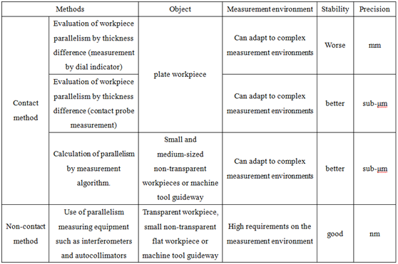
3. Comparison of Different Parallelism Measurement Methods
References
- Ankara Huseyin, Yerel Suheyla; Use of range control charts in determination of variability in surface parallelisms of plates. Journal of Scientific & Industrial Research 2008, 67(12), 1078-1082.
- Maurizio Vannoni, Roberto Bertozzi; Parallelism error characterization with mechanical and interferometric methods. Optics and lasers in engineering 2007, 45(6), 719-722.
- Jooho Hwang, Chun-Hong Park, Wei Gao, Seung-Woo Kim; A three-probe system for measuring the parallelism and straightness of a pair of rails for ultra-precision guideways. International Journal of Machine Tools and Manufacture 2007, 47(7-8), 1053-1058.
- 4. Tung-Hsien Hsieh, Hsueh-Liang Huang, Wen-Yuh Jywe, Chien-Hung Liu; Development of a machine for automatically measuring static/dynamic running parallelism in linear guideways. Review of Scientific Instruments 2014, 85(3), 035115.
- Alan Campbell; Measurement of lathe Z-slide straightness and parallelism using a flat land. Precision engineering 1995, 17(3), 207-210.
- Ye Xiuling, Zhao Yan, Wang Yiwen, Wang Zhong, Fu Luhua. Parallelism measurement for base plate of standard artifact with multiple tactile approaches. International Conference on Optical Instruments and Technology: Optoelectronic Measurement Technology and Systems, 2017.
- Xi Chen, Changku Sun, Luhua Fu, Changjie Liu. A novel reconstruction method for on-machine measurement of parallel profiles with a four-probe scanning system. Precision Engineering, 2019, 59: 224-233.
- Jianlong Zhao, Yong Sang, Fuhai Duan, Xiaomeng Ji, Zhuowen Lin. High-precision surface parallelism measurement using digital image correlation method. Optical Engineering, 2019, 58(9): 094105.
- J. H. Wasilik, T. V. Blomquist, C. S. Willett. Measurement of parallelism of the surfaces of a transparent sample using two-beam nonlocalized fringes produced by a laser. Applied optics, 1971, 10(9): 2107-2112.
- 兰斌, 冯国英, 张涛. 用于透明平板平行度和均匀性测量的单元件干涉仪. 物理学报, 2017, 66(6): 69501-069501.
- J.C. Bhattacharya. Measurement of parallelism of the surfaces of a transparent sample. Optics and lasers in engineering, 2001, 35(1): 27-31.
- Yanxiong Niu, Haisha Niu, Ning Liu, Jiang Li. KTP crystal thickness distribution measurements based on laser feedback interferometry. Applied optics, 2014, 53(19): 4195-4199.
- Yang Yi, Zhang Lin, Shi Zhendong, Ma Hua, Ren Huan. Parallelism measurement of plane glass at oblique incidence by interferometry. International Conference on Optical Instruments and Technology: Optical Systems and Modern Optoelectronic Instruments, 2017.
- Parks R E, Shao L, Davies A D, et al. Haidinger interferometer for silicon wafer TTV measurement. International Society for Optics and Photonics, 2001, 4344: 496-505.
- Maurizio Vannoni, Giuseppe Molesini. Joint interferometric measurement of planarity and parallelism. Optical Engineering, 2004, 43(5): 1215-1221.
- Shin-ichi Itoh, Yoshiki Yamazaki, Kentaro Katoh,Jun Chen. High precision testing method for Fabry-Perot etalon. Optical review, 2001, 8(3): 179-183.
- Bruce P. Konkel, Earl C. Zipter, Edward E. Kirkham. Improved parallelism measurement using a laser interferometer. IEEE Transactions on Industry Applications, 1991, 27(4): 606-610.
- T. G. Bergman, J. L. Thompson. An interference method for determining the degree of parallelism of (laser) surfaces. Applied optics, 1968, 7(5): 923-925.
- Peter de Groot, Jim Biegen, Jack Clark, Xavier Colonna de Lega, David Grigg. Optical interferometry for measurement of the geometric dimensions of industrial parts. Applied Optics, 2002, 41(19): 3853-3860.
- Xavier Colonna de Lega, Peter de Groot, David Grigg. Dimensional measurement of engineered parts by combining surface profiling with displacement measuring interferometry. Proceedings of Fringe 2001: the Fourth International Workshop on Automated Processing of Fringe Patterns. Elsevier, Paris, 2001: 47-55.
- Jaramillo-Nunez A, Robledo-Sanchez C, Cornejo-Rodriguez A. Measuring the parallelism of transparent and nontransparent plates. Optical Engineering, 1996, 35.
- Zhi-shan Wang, Yue-jin Zhao, Zhuo Li, Liquan Dong, Xuhong Chu. An overlapping technique to measure the parallelism of surface elements in a large area based on comparison goniometer. Instrumentation, Metrology, and Standards for Nanomanufacturing IV. International Society for Optics and Photonics, 2010, 7767: 77670S.
- Li Xiangning, He Liqing, Guo Hanming. Noncontact Direct Measurement on Parallelism and Verticality of a Small Size work Part. International Symposium on Precision Mechanical Measurements, 2002,99-103.
- 柯金昌, 梁秀玲. 基于MATLAB 的平板玻璃不平行度快速检测设计. 电子测量技术, 2011, 34(12): 92-96.
- Qian Liu, Ryoji Ohba. A simple real-time method for checking parallelism between the two gratings in Talbot interferometry. Optics communications, 2000, 175(1-3): 19-26.
- 符红, 吴琼, 林斌, 曹向群. 基于双光栅的平行度检测. 光电工程, 2012,39(7):61
- Deepa Joshi, Ashok Kumar, Yudhisther Kumar, Reeta Gupta. Evaluation of parallelism by ultrasonic echo method. Applied acoustics, 2010, 71(5): 446-450.