Submitted Successfully!
To reward your contribution, here is a gift for you: A free trial for our video production service.
Thank you for your contribution! You can also upload a video entry or images related to this topic.
Version Summary Created by Modification Content Size Created at Operation
1 + 1706 word(s) 1706 2021-10-09 06:12:18 |
2 format correct Meta information modification 1706 2021-10-25 03:21:57 | |
3 format correct Meta information modification 1706 2021-10-29 08:49:38 | |
4 The format is correct Meta information modification 1706 2021-11-12 09:20:01 |

Video Upload Options

Do you have a full video?

Confirm

Are you sure to Delete?
Cite
If you have any further questions, please contact Encyclopedia Editorial Office.
Singh, R. Determination of KISCC by The Circumferential Notch Tensile. Encyclopedia. Available online: https://encyclopedia.pub/entry/15326 (accessed on 25 April 2024).
Singh R. Determination of KISCC by The Circumferential Notch Tensile. Encyclopedia. Available at: https://encyclopedia.pub/entry/15326. Accessed April 25, 2024.
Singh, Raman. "Determination of KISCC by The Circumferential Notch Tensile" Encyclopedia, https://encyclopedia.pub/entry/15326 (accessed April 25, 2024).
Singh, R. (2021, October 25). Determination of KISCC by The Circumferential Notch Tensile. In Encyclopedia. https://encyclopedia.pub/entry/15326
Singh, Raman. "Determination of KISCC by The Circumferential Notch Tensile." Encyclopedia. Web. 25 October, 2021.
Determination of KISCC by The Circumferential Notch Tensile
Edit

Stress corrosion cracking (SCC) is a vexing problem for load-bearing equipment operating in a corrosive environment in various industries, such as aerospace, chemical and mineral processing, civil structures, bioimplants, energy generation etc. For safe operation, effective maintenance and life prediction of such equipment, reliable design data on SCC (such as threshold stress intensity for SCC, i.e., KISCC) are invaluable. Generating reliable KISCC data invariably requires a large number of tests. Traditional techniques can be prohibitively expensive. Circumfrential notch tensile testing is a relatively recent, much simpler and cost-effective approach to generating accurate and reliable KISCC data.

stress corrosion cracking (SCC) threshold stress intensity for SCC (KISCC) circumferential notch tensile (CNT) testing steel magnesium

1. Introduction

Stress corrosion cracking (SCC), i.e., a premature, sudden and sometimes catastrophic fracture, results from the synergy of corrosive medium and tensile stress. Because SCC is among the most catastrophic and dangerous types of degradation of metals/alloys caused by corrosion, it is a critical material selection criterion for load-bearing equipment designed for corrosive conditions. SCC is a critical concern because [1][2][3]:
(a)
It can occur at stresses even below the yield strength of the material;
(b)
Cracks can grow undetected into leaks or, sometimes, sudden and catastrophic failures when the required synergy of stress and environment is present;
(c)
A few localized and fine cracks may grow undetected to fracture, while the alloy surface may virtually appear free from corrosion;
(d)
It is intriguing that sometimes a relatively less corrosive environment may be more deleterious for SCC.
Mechanism, monitoring and mitigation of SCC are of great research and commercial interests, since SCC is a critical concern for a vast number of industrial equipment operating in corrosive environment, and its timely circumvention is critical for safe plant operation and maintenance [3]. Sometimes, in-service monitoring of the susceptibility to SCC may be required for the remaining life assessment and safe operation, whereas there may be occasions when the characterisation of SCC of a failed equipment may assist in the mitigation of likely SCC of other operating members. Given the stochastic nature of SCC, a confirmation of the phenomenon and reliable implementation of mitigation measures may require a vast number of tests. Therefore, it is very attractive to have an accurate, inexpensive and rapid technique for the characterization of susceptibility to and the generation of design data for SCC.
U-bend and C-ring testing are used for in-service monitoring of SCC [2][3] but they may represent excessively high loadings. On the other hand, a commonly employed laboratory technique, slow strain rate testing (SSRT), only provides a ‘go, no-go’ type of assessment [2][3]. Designing equipment that handle corrosive conditions in service or life extension/prediction of such equipment requires data on the likelihood of existing surface defects/cracks to undergo corrosion-assisted growth. This requires the determination of the threshold of the stress intensity factor (KI) for growth of a pre-existing surface defect/crack [1]. However, in a corrosive environment, KI can be influenced by the corrosion at the tip of a crack. Therefore, the threshold of the stress intensity factor with corrosion influencing at the crack tip, i.e., KISCC, has to be determined for an alloy–environment system susceptible to SCC.
For valid fracture mechanics testing, it is necessary that the specimens meet the requirements of plain strain. In order to meet the requirements, the specimens for KISCC determination using traditional techniques are generally bulky, e.g., double-cantilever beam (DCB), cantilever beam (CB), compact tension (CT), centre-cracked, surface flawed (SF) test specimens [4]. Because of their bulky size and complex geometries, the fabrication of DCB, centre-cracked or CT specimens is expensive. Further, testing of such bulky specimens require high-capacity loading machines and long test times, which can be a prohibitive proposition, since the generation of reliable and statistically valid KISCC data may necessitate conducting a large number of tests. Another limitation with these specimen types is the inability to employ them when material of sufficiently thick dimensions is not available, e.g., a thin-walled component or a heat-affected zone (HAZ) in a weldment. Hence, it is extremely attractive to find a technique that can enable an accurate, cost-effective and rapid determination of KISCC using specimens of thin cross-sections (cf. DCB, centre-cracked or CT specimens).

2. Circumferential Notch Tensile (CNT) Testing for KISCC: Distinct Advantages

Circumferential notch tensile (CNT) specimens (shown in Figure 1) that have been used extensively in the past 15 years for the generation of valid KISCC data [1][5][6][7] circumvent all the concerns with the traditional specimen geometries (e.g., DCB, centre-cracked or CT), i.e., (a) bulky size, (b) complex geometry, (c) high-capacity loading system for achieving the loads required for large cross sections and (d) inability to test where only thin sections are available (such as HAZ of weldments or a failed thin-walled component).
Figure 1. Circumferential notched tensile (CNT) specimen (all dimensions in mm) [6].
The distinct advantages of a small cross section of a CNT specimen are [1][7]:
(a)
It enables achieving high stress intensities (KI) by employing small loads;
(b)
It is much easier to machine the simple cylindrical specimen geometry than the CT or DCB geometry;
(c)
It is much cheaper to fabricate the specimens (cf. 20–25% of CT or DCB specimens);
(d)
Enables testing when only thin sections are available (such as HAZ of weldments or a failed thin-walled component);
(e)
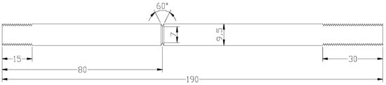
It vastly reduces the amount of the required test material. In fact, the required test material can be further reduced considerably by using extenders. The extenders constructed out of another material can be used because the actual area of interest is only the notched portion and the adjacent area (shown in Figure 1). This enables just machining the small cylindrical sample with circumferential notch and then extending it to the full length by drilling threads on both ends (and then using extenders of a harder material to extend the length at each end);
(f)
The ability to test small cylindrical samples (as described at (e) above) enables testing where only small lengths of test material may be available or where the test material is expensive (for example, when a large number of tests are required for assessing a pressure vessel constructed out of an expensive duplex stainless steel).
It is important to note CNT specimens soundly comply with the plane strain condition and low plasticity criteria in spite of their small size [8][9][10].

2.1. CNT Specimens for the Determination of KISCC: Challenges and Circumvention

For determination of KISCC, a crack growth parameter (such as time-to-fail, Tf)), is determined at different values of stress intensity factor (KI) while the specimens are immersed in the corrosive fluid. KISCC is determined from the plot of Tf vs. KI. One may wonder, cylindrical geometry being so simple, why the CNT specimens were not used for the determination of KISCC until just 15 years ago. The reason lies in the complication that arises due to the eccentric nature of the pre-crack that develops during rotating–bending employed for pre-cracking of cylindrical specimen, which causes bending during tensile loading that can vastly compromise the accuracy of KI. Accuracy in the measurement of KI is crucial for a precise determination of KISCC. KI of CNT specimens is determined, as described, through the Equations below [8]:
where
The parameters in Equations (1)–(7) are: σt, tensile stress (unit, Pa); σb, bending stress (Pa); Fo, geometric function for round specimens with eccentricity (no unit); F, geometric function (no unit) without eccentricity for round specimens (no unit); a, effective crack length (m); D, specimen diameter (m); d, equivalent ligament diameter (m); P, applied load (N); ε, eccentricity (m); α, a constant (no unit) calculated from Equation (7).

2.2. Accounting for Eccentricity (ε) in Pre-Cracked CNT Specimens

As described earlier, the pre-crack that is introduced in a cylindrical specimen by subjecting it to rotating–bending fatigue can cause an eccentric ligament (as shown in an example in Figure 2). This eccentricity causes a critical problem in an accurate determination of KISCC by the CNT technique. As shown in Equation (1), KI of specimen with an off-centre pre-crack will have a contribution of bending stress (σb), in addition to tensile stress (σt). Accordingly, it is essential that the bending force due to eccentricity is accounted for, for an accurate calculation of KI. [1]. Employing a specific method, the centroid of the eccentric ligament was determined, which enabled the determination of the bending stress experienced by the specimen due to the eccentricity. The details of the specific method can be found elsewhere [1].

In a nutshell, the effective crack length (a) in Equation (1) is used for the first estimate of KI, which enables the determination of the Irwin correction factor (ry) from Equation (8), and (a¯) from Equation (9). Thus, Equation (1) enables the determination of KI.

where σy is 0.2% offset tensile yield stress (Pa). Using a in Equation (2), the first estimate of KI is determined. a¯ (instead of a) is used for the calculation of KI. The reason for this correction is described elsewhere [11,12,13,14].

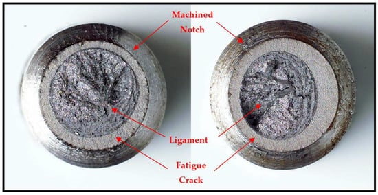
Figure 2. Eccentricity of fatigue crack in a CNT specimen that was subjected to rotating–bending fatigue [1].

2.3. Valid KI Data

The implementation of elastic fracture mechanics (LEFM) for the determination of KI assumes primarily an elastic deformation and brittle state of the material. In reality, there is invariably some contribution of plastic deformation at the crack tip before a crack propagates. Therefore, the LEFM approach allows for a small plastic zone, as long as its contribution is negligibly insignificant, which necessitates the specimen size to be large. For its implementation, two specifications have been developed for determining the validity of the measured KI, as described below [8,9,10]:

whereaf=ε+(D−2amd)2, and σN is the nominal applied stress in the final ligament (Pa).

In other words, the validity requirements insist that: (i) the correction in depth due to the Irwin plastic zone (ry) should be at least half of the fatigue pre-crack depth (af) [10][11][12] and (ii) the average of the stress across the ligament produced upon fatigue pre-cracking (σN) should be smaller than 2.5 times the yield strength (σy). In the context of pre-cracked CNT specimens that may have eccentric final ligament, these validity specifications can also apply (where the maximum nominal stress has contributions from both the tensile and the bending stresses which should be <2.5 σy). Also, for such eccentric ligaments, the greatest depth of the crack is taken to be the fatigue crack depth (af).

References

  1. Raman, R.K.S.; Rihan, R.; Ibrahim, R.N. A novel approach to the determination of the threshold for stress corrosion cracking (K ISCC) using round tensile specimens. Metall. Mater. Trans A 2006, 37A, 2963–2973.
  2. Sedriks, A.J. Stress Corrosion Cracking Test Methods; Publications of National Association of Corrosion Engineers: Houston, TX, USA, 1990.
  3. Dean, S.W.; Pugh, E.N.; Ugiansky, G.M. Environment-Sensitive Fracture: Evaluation, and Comparison of Test Methods, ASTM STP 821, Symposium Sponsored by ASTM Committee G-1; ASTM: Philadelphia, PA, USA, 1982.
  4. Turnbull, A. Test methods for environment assisted cracking. Br. Corros. J. 1992, 27, 271–289.
  5. Raman, R.K.S.; Rihan, R.; Ibrahim, R.N. Role of imposed potentials in threshold for caustic cracking susceptibility (KISCC): Investigations using circumferential notch tensile (CNT) testing. Corros. Sci. 2007, 49, 4386–4439.
  6. Rihan, R.; Raman, R.K.S.; Ibrahim, R.N. Determination of crack growth rate and threshold for caustic cracking (KIscc) of a cast iron using small circumferential notched tensile (CNT) specimens. Mater. Sci. Eng. A 2006, 425, 272–277.
  7. Raman, R.K.S.; Rihan, R.; Ibrahim, R.N. Validation of a novel approach to determination of threshold for stress corrosion cracking (KISCC). Mate. Sci. Eng. A 2007, 452–453, 652–656.
  8. Ibrahim, R.N.; Stark, H.L. Establishing K 1c from eccentrically fatigue cracked small circumferentially grooved cylindrical specimens. Int. J. Fracture 1990, 44, 179–188.
  9. Ibrahim, R.N.; Kotousov, A.G. Analytical approach for calculating KIC from eccentrically cracked cylindrical specimens. ASME Press. Vessel. Pip. Conf. 1999, 388, 155–161.
  10. Ibrahim, R.N.; Stark, H.L. Estimating fracture toughness from small specimens. Eng. Fract. Mech. 1986, 25, 395–401.
  11. Ibrahim, R.N. Eccentricity Correction for the Evaluation of Fracture Toughness from Cylindrical Notched Test Small Specimens. Eng. Fract. Mech. 1999, 64, 49–58.
  12. Ibrahim, R.N.; Stark, H.L. Validity requirements for fracture toughness measurements obtained from small circumferentially notched cylindrical specimens. Eng. Fract. Mech. 1987, 28, 455–460.
More
Information
Contributor MDPI registered users' name will be linked to their SciProfiles pages. To register with us, please refer to https://encyclopedia.pub/register :
View Times: 1.3K
Revisions: 4 times (View History)
Update Date: 12 Nov 2021
1000/1000