Hydrothermal liquefaction is a high-temperature high-pressure thermochemical conversion method adapted to convert high-water content biomass feedstocks to biofuels and many other valuable industrial chemicals. The hydrothermal process is broadly classified into carbonization, liquefaction, and gasification with hydrothermal liquefaction conducted in the intermediate temperature range of 250–374 °C and pressure of 4–25 MPa. Over the years, various solvents and co-solvents have been used as conversion mediums to promote easy decomposition of the lignocellulosic components in biomass. To obtain the final products, the product separation process typically involves multiple extraction and evaporation steps, which greatly depend on the type of extractive solvents and process parameters. In general, the main aim of the hydrothermal process is to produce a primary product, such as bio-oil, biochar, gases, or industrial chemicals, such as adhesives, benzene, toluene, and xylene.
1. Introduction
In the recent past, our dependence on technology and energy needs has increased significantly, either in the form of energy consumption for personal use, household purposes, transportation, or agricultural needs. Most of this energy demand is met from fossil fuels such as coal, petroleum, and natural gas. The excessive use of fossil fuels results in increased emissions of oxides of nitrogen, sulfur, mercury, and other trace elements, which are very harmful to human health and vegetation. Apart from these emissions, the use of fossil fuels results in greenhouse gas emissions leading to global warming and drastic climate changes
[1]. The depletion of fossil fuels was one of the prominent issues, but now the environment is a much larger concern, forcing researchers to investigate alternative renewable and sustainable sources of energy.
Energy derived from biomass and biomass waste/residue is attracting a lot of attention. The term biomass refers to all biological matter, i.e., plants, animals, microorganisms, agricultural and forestry residue/waste, marine waste, and municipal and industrial organic waste that is directly or indirectly derived from the process of photosynthesis
[2][3]. Biomass is an abundant, cheap, renewable, and environmentally friendly source of energy. Biomass and biomass waste can be used as a fuel, commonly called biofuel, which is produced from organic matter. It is more difficult to handle, store, and transport biomass than to do the same with conventional solid, liquid, and gaseous fossil fuels
[4][5]. Biomass is bulky and has low energy density, and a high moisture and low ash content
[4][6]. Hence, over the years, numerous technologies and methods have been explored to convert biomass into high-density, clean, and easy-to-handle solid, liquid, and gaseous fuels. The first-generation biofuel sources, such as corn, edible oils, and other cereals, are also required to fulfill dietary needs, while the second-generation biofuel sources, such as agricultural and forest residues, wood chips, and pulp/paper remains are available in abundance and can be converted into biofuel. The biofuel from second-generation resources can be produced mainly through biochemical and thermochemical pathways. The thermochemical routes comprise a vast range of technologies, such as combustion, pyrolysis, gasification, and hydrothermal liquefaction (HTL). As biomass contains large amounts of inherent moisture, the thermal treatment—especially combustion, pyrolysis, and gasification of biomass without drying—is problematic and less efficient.
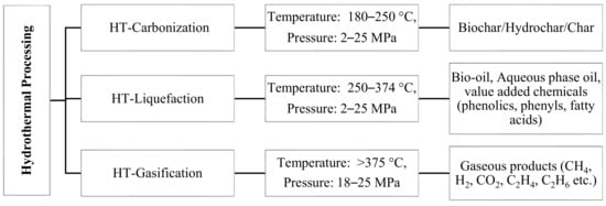
The hydrothermal (HT) process can handle resources with high moisture. HT processing involves the thermochemical conversion of biomass in the presence of a hot and pressurized solvent medium long enough to hydrolyze and degrade the lignocellulosic matter into biofuel
[3]. HT processes are broadly classified into three categories depending on temperature and pressure conditions, as shown in
Figure 1. The operation that occurs at a temperature range of 180–250 °C and pressures of 2–10 MPa is called HT carbonization, and the major product obtained is char
[7]. The operation that occurs at an intermediate temperature range between 250 and 374 °C and pressures of 2–25 MPa is HT liquefaction (HTL) and is used to produce high energy-dense liquid fuels, such as bio-oil
[8][9]. The major product above critical condition of water 374 °C, 22 MPa is gas, the operation in this zone is called HT gasification
[10]. HTL is a very broad topic, which involves the study of several parameters for its complete understanding.
Figure 1. Different hydrothermal processing routes, reaction condition, and products (HT–hydrothermal)
[3][11][12][13][14][15][16][17][18].
2. Hydrothermal Liquefaction
HTL is also known as hydrothermal treatment or hydrothermal upgrading. As shown in
Figure 1, the optimum range of HTL operations is in the temperature range of 250–374 °C with a final pressure of 2–25 MPa. In general, water is used as a process medium. Using water as a medium benefit the hydrolysis reaction that occurs in HTL. Removing moisture can be a costly pre-treatment step in techniques like combustion, pyrolysis, and gasification. However, as there is no need to pre-treat biomass to remove moisture, HTL is considered a more economical alternative for bio-oil production. HTL has been used for a long time. A recent review by Gollakota et al.
[19] provides a detailed history of the evolution of HTL.
3. Major Lignocellulosic Biomass Feedstocks and HTL Mechanism
Agricultural and forest residue are two main sources of lignocellulosic biomass. The name lignocellulosic mainly describes the key structural components—lignin, cellulose, and hemicellulose—present in agricultural and forest biomass. The elemental composition mainly consists of carbon, hydrogen, and oxygen with traces of nitrogen, sulfur, and mineral impurity. Some major feedstocks along with their structural and elemental compositions are described in Table 1.
Table 1. Chemical and elemental composition of major feedstock and bio-oil yield.
| Feedstock |
Cellulose |
Hemicellulose |
Lignin |
Carbon |
Hydrogen |
Oxygen |
H/C |
O/C |
Bio-Oil |
Ref. |
| Agricultural Feedstock |
| Corn straw |
30.81 |
25.52 |
16.76 |
44.57 |
5.53 |
33.70 |
1.49 |
0.57 |
7.9 |
[20] |
| Peanut straw |
36.56 |
20.27 |
18.36 |
41.42 |
5.51 |
35.21 |
1.60 |
0.64 |
14.6 |
[20] |
| Rice straw |
46.33 |
31.09 |
10.17 |
41.34 |
5.33 |
34.29 |
1.55 |
0.62 |
15 |
[20] |
| Soybean straw |
42.39 |
22.05 |
18.93 |
45.99 |
6.07 |
39.00 |
1.58 |
0.64 |
15.8 |
[20] |
| Corn stover |
45.00 |
30.00 |
16.00 |
43.57 |
5.84 |
49.98 |
1.61 |
0.86 |
27.15 |
[21][22] |
| Rice straw |
42.87 |
25.15 |
31.97 |
38.55 |
5.50 |
55.34 |
1.71 |
1.08 |
27.6 |
[23] |
| Barley straw |
46.00 |
23.00 |
15.00 |
44.66 |
6.34 |
47.97 |
1.70 |
0.81 |
34.9 |
[24] |
| Castor residue |
38.42 |
22.40 |
20.20 |
43.59 |
5.56 |
46.16 |
1.53 |
0.79 |
15.8 |
[25] |
| Pre-treated sorghum bagasse |
49.84 |
8.01 |
24.65 |
43.20 |
5.80 |
41.40 |
1.61 |
0.72 |
23.42 |
[26] |
| Forest Feedstock |
| Oakwood |
38.10 |
23.00 |
32.00 |
50.20 |
7.00 |
42.80 |
1.67 |
0.64 |
23.17 |
[27][28] |
| Palm kernel shell |
24.50 |
22.90 |
33.50 |
47.77 |
4.06 |
47.55 |
1.02 |
0.75 |
24 |
[29] |
| Empty fruit bunch |
26.60 |
26.90 |
18.60 |
43.62 |
4.03 |
50.22 |
1.11 |
0.86 |
16 |
[29] |
| Palm mesocarp fiber |
23.10 |
22.20 |
30.60 |
46.29 |
4.67 |
47.37 |
1.21 |
0.77 |
16 |
[29] |
| Poplar wood |
52.16 |
18.92 |
22.97 |
47.04 |
5.60 |
43.20 |
1.43 |
0.69 |
28.49 |
[30] |
| Birch sawdust |
45.30 |
24.20 |
22.90 |
48.50 |
6.30 |
45.20 |
1.56 |
0.70 |
22.3 |
[31] |
| Aspen wood |
47.14 |
19.64 |
22.11 |
50.39 |
6.19 |
43.23 |
1.47 |
0.64 |
20.65 |
[32] |
| Datura stramonium L. stem |
42.20 |
23.13 |
24.33 |
43.55 |
5.98 |
49.70 |
1.65 |
0.86 |
32 |
[33] |
| Poplar wood |
44.95 |
34.05 |
25.85 |
46.72 |
6.18 |
46.96 |
1.59 |
0.75 |
17.5 |
[34] |
| Furniture sawdust |
32.63 |
37.23 |
22.16 |
47.42 |
5.67 |
46.71 |
1.43 |
0.74 |
12.1 |
[35] |
| Cypress |
46.30 |
27.60 |
28.80 |
48.90 |
6.00 |
44.80 |
1.47 |
0.69 |
27.5 |
[36] |
| Pine |
39.54 |
20.61 |
30.15 |
49.52 |
6.49 |
43.89 |
1.57 |
0.66 |
24.2 |
[37] |
| Paulownia |
42.35 |
25.22 |
23.44 |
45.50 |
6.30 |
48.20 |
1.66 |
0.79 |
27.01 |
[38] |
| Oil palm shell |
39.70 |
21.80 |
32.50 |
50.01 |
7.66 |
29.02 |
1.84 |
0.44 |
18.5 |
[39] |
| Beech wood |
45.05 |
31.50 |
22.25 |
44.68 |
6.08 |
49.24 |
1.63 |
0.83 |
22 |
[40] |
| Scotch pine |
47.30 |
20.54 |
27.70 |
48.33 |
6.49 |
45.18 |
1.61 |
0.70 |
24.6 |
[41] |
Cellulose is a homo-polysaccharide formed by the linearly coupled D-glucopyranoside units connected by β-glycosidic linkages in a 1:4 fashion
[42]. Increased packing density in cellulose structure leads to the formation of crystalline structures, which are insoluble in an aqueous medium under normal conditions and require rigorous treatment for hydrolysis and degradation, whereas the non-crystalline structure is easily hydrolyzed
[43][44]. Hemicellulose is mainly composed of D-glucose, D-xylose D-mannose, and D-galactose along with some other glycosyls. It has a poor structural formation leading to a reduced crystallinity, making it more susceptible to water
[2]. Lignin is a three-dimensional structure made of ether bonds and C–C linkages. The three main monomeric units of lignin are p-coumaryl alcohol, coniferyl alcohol, and sinapyl alcohol
[14].
3.1. Cellulose Decomposition
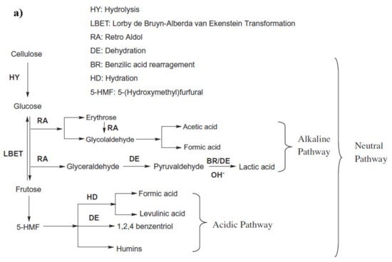
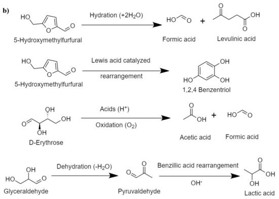
In the hydrothermal process, cellulose reacts with water at an elevated temperature, which breaks the hydrogen bond in the cellulose, weakening its crystallinity. Cellulose is hydrolyzed into glucose, fructose, and other monomeric units, which is followed by further degradation of these units in simpler hydrocarbons. The pathway of cellulosic hydrolysis and C–O–C bond cleavage can be different according to the acid, the base, and the neutral medium, as shown in
Figure 2a
[45]. For instance, acid hydrolysis takes place by the reaction of the acidic proton and oxygen that bonds two glucose units and forms the conjugated acid, which, on the cleavage of glycosidic bonds, forms two glucose units
[46]. In basic medium, the breaking of the C–O–C bond occurs when the OH
− attacks at the anomeric carbon, whereas in the presence of water, the glycosidic unit and water split at the same time and form two glucose units
[47].
Figure 2. (
a) Proposed routes of HTL of cellulose (adapted Sudong et al.
[45]), copyright from Elsevier 2012, (
b) major intermediate reactions during HTL of cellulose.
Hirano et al.
[48] presented the plausible mechanism for cellulose hydrolysis and inferred that the major monomeric units formed are glucose and fructose, which, on condensation and isomerization, produce unstable intermediates, such as erythrose, glycolaldehyde, dihydroxyacetone, and its reversible isomer, glyceraldehyde. Erythrose on hydrogenation produces erythritol. The intermediate erythritol and glyceraldehyde further dehydrate to form 2,3-butanedione and pyruvaldehyde, respectively. Some major intermediate reaction that occurs during HTL of cellulose is shown in
Figure 2b. In the presence of catalysts that promote hydrogenation, these intermediates result in the formation of stable C
2–C
3 alcohols, such as 3-hydroxy-2-butanone, hydroxy acetone, 2,3-butanediol, propylene glycol, and ethylene glycol.
Li et al.
[49] found the final composition from cellulose HTL to be a mixture of esters, aldehydes, ketones, and a small fraction of alcohol, and ether. Esters, being the most abundant, were devised to be formed via an α-hydrogen donation to intermediates, resulting in the formation of majorly 2-hydroxy-acetic acid ethyl ester, 2-hydroxy propanoic acid ethyl ester, and 4-oxo-pentanoic acid ethyl ester. The aldehyde and ketones formed because of a series of decomposition, dehydration, isomerization, and aldol reactions. Gao et al.
[50] investigated the effect of temperature on cellulose decomposition and found that at 200 °C, 50% of the products were 5-HMF (5-hydroxy methyl-2-furancarboxaldehyde), 10% were ketones (major: 4-hydroxy-4-methyl-2-pentanon), and 5% were acids, such as acetic acid, levulinic acid, and n-hexadecanoic acid. At higher temperatures of 300–400 °C, products were more distributed in a class of acids, aldehydes, ketones, furans, esters, phenols, phenyl, and nitrogenous compounds.
In order to understand the degradation characteristics of empty fruit bunch, Miyata et al.
[51] studied the effect of model substrates (cellulose, xylan, glucose, xylose, dihydroxyacetone, pyruvaldehyde, and hydroxyacetone) in enhancing the yield of water-soluble (WS) product. Later, through catalytic cracking the WS product was converted to bio-oil. It was found that non-catalytic HTL of cellulose, xylan, glucose, and xylose yielded 58 wt%, 64 wt%, 53 wt%, and 64 wt% of WS, respectively. In case of Fe-assisted HTL, the production of WS from cellulose increased to 93 wt%, glucose to 74 wt%, and xylan and xylose both to 80 wt%. It can be said that cellulose can significantly enhance the production of bio-oil in the presence of metal catalysts.
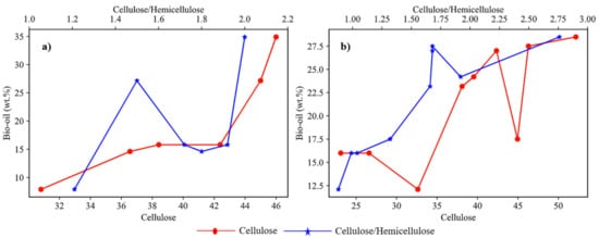
The yield of bio-oil significantly depends on the biochemical composition of biomass. The weight percentage of cellulose content and the ratio of wcellulose/whemicellulose in biomass are two important factors affecting the yield. Figure 3a shows the plots of different studies involving agricultural feedstock with varied composition. These studies showed that cellulose content plays a dominant role in deciding the yield of bio-oil in the case of agricultural feedstock. The plotted analysis of results from previous studies on different forest-based feedstocks as shown in Figure 3b it was observed that the wcellulose/whemicellulose ratio was dominant over the cellulose content in determining the bio-oil yield for forest feedstock.
Figure 3. Effect of cellulose and cellulose/hemicellulose ratio on bio-oil yield for (
a) agricultural feedstocks
[20][21][22][23][24][25], (
b) forest feedstock
[23][24][26][29][30][32][35][37][38].
3.2. Lignin Decomposition
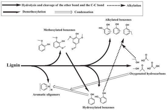
The ether bond connecting three basic phenylpropane units in lignin has a low bond dissociation energy and the macromolecular unit is hydrolyzed in the presence of sub- and supercritical water, forming the basic units of p-coumaryl alcohol, coniferyl alcohol, and sinapyl alcohol. The basic units undergo further dissociation by hydrolysis of the side C–C bonds to form aromatics
[52]. The primary components obtained during softwood lignin decomposition are guaiacols, catechols, and alkylphenols. Guaiacols, catechols, and alkylphenols are mostly formed via hydrolysis and the breaking of ether and C–C bonds. In a high temperature HTL environment, catechols and alkylphenols are also formed through the demethoxylation of guaiacols and the alkylation of hydroxylated benzene, respectively
[52][53]. The formation of cresols, ethyl phenols, and methyl benzenediols takes place through the alkylation of respective phenols and benzenediols as shown in
Figure 4 [54][55]. Nguyen et al.
[56] performed a temperature study on the product composition of lignin liquefaction and found that the fraction of guaiacols and phenolics dimers decreased significantly when the temperature in the sub-critical zone increased at the same time that the fraction of alkylphenols, anisoles, and catechols increased. In summary, cellulose and hemicellulose mainly contribute to the formation of acids, esters, fatty acid alkyl esters, ketones, aldehydes, furans, alcohols, and ether, whereas lignin mostly dissociates to form aromatic compounds.
Figure 4. Proposed pathway for hydrothermal lignin decomposition
[55], copyright Elsevier 2013.
4. Hydrothermal Liquefaction Process
4.1. Batch Process
Most HTL experiments have been studied in a batch reactor at a laboratory scale, though there has been a significant improvement in pilot-scale studies in a continuous system over the last 10 years. In general, the batch reactor studies have been carried out in a cylindrical autoclave reactor made of either stainless steel, Hastelloy C-22, or Inconel-625 with a typical size of 100–1000 mL. Some studies used a tubular reactor (25 mL) made of stainless steel, whereas a self-assembled Swagelok port connector and caps also serve as a batch reactor
[57]. The typical assembly of a batch reactor consists of a stirrer, inlet and outlet tubes, valves for gas pressurization and depressurization, a heating and cooling system, temperature detector, pressure gauge, and controller. The heating system can be either an external electric furnace, coil heating, or sand bath heating. The cooling system can be an electric fan or chilled water with a tubular coil. Other than that, the reactor is connected to a gas cylinder to provide an initial pressure (inert gas) to prevent a phase change during the process. It also contains a temperature detector. Once the reactor is loaded with feedstock and solvent, it is purged with an inert gas and pressurized with either an inert gas or a process gas. One common challenge faced with conventional batch reactor is the long time it takes to reach the final process temperature and similarly long time required for its cooling, which notably increases the overall time spend by-products at a relatively high subcritical temperature regime. The problem with the long heating time is the side reactions associated with it, which decreases the total oil yield. Brand et al.
[58] discussed the effect of heating rate on bio-oil yield and found that a combination of fast heating rate, high temperature, and immediate quenching can highly improve the yield of bio-oil. Another problem associated with the batch reactor is the improper mixing of biomass-water slurry, which leads to the formation of dead zones at bottom corners. The biomass accumulates in the dead zones, giving rise to incomplete conversion and formation of char.
4.2. Continuous Process
In the batch process, the reactor takes a long time to reach the final temperature; the long heating time to reach subcritical temperature promotes enhanced degradation. However, the process with the final temperature as the critical condition of water, the heating time is significantly longer; this long heating time promotes a side reaction, resulting in intermediate formation, repolymerization, and cracking. One objective of moving from a batch to a continuous system is to achieve a fast-heating rate at high temperature. The heating time in the continuous system is adequate to support easy hydrolysis and decomposition of biomass while eliminating side reactions, which happen during a long heating time. Converting higher amounts of biomass in a small processing unit requires a high-pressure feeding system for concentrated biomass slurries, which is another technological challenge in process development
[10].
Limited research has been conducted in the field of a large-scale continuous HTL process for bio-oil production using lignocellulosic biomass. Toor et al.
[59] studied the catalytic liquid conversion of wet distillers’ grain with solubles (WDGS) in a 30 dm
3 h
−1 continuous pilot plant at a subcritical temperature of 350 °C and a pressure of 25 MPa with the feed flow maintained at 11 dm
3 h
−1. A high-pressure feed pump and recirculation pump were used to maintain a high flow rate. In order to heat the feed mixture quickly, the recirculating pump was designed to supply nine parts of pre-heated feed to mix with one part of new feed, which then reached the operative temperature with a small addition of heat through a trim heater. Mørup et al.
[60] developed a batch autoclave assembly, which he called a stop-flow reactor system. It had a capacity of 170 mL with inlets and outlets allowing injection of feed and ejection of the product one at a time at elevated temperatures. The system also had a high pressure to maintain the temporary flow mode in reactor. The reactor supported fast heating and performed multiple identical runs in a sequence without needing to be cooled. High-pressure pneumatic pumps were used to inject and eject materials.
Anastasakis et al.
[61] used an Aarhus University pilot-scale HTL reactor for liquefaction of miscanthus, spirulina, and sewage sludge. The HTL system was a 140 m long tubular set-up of a constant cross-section (14.2 mm) with a total system volume of 20 L. The feeding system consisted of a progressive cavity pump for continuous recirculation slurry in a hopper. To support an efficient flow rate, a positive displacement pump with a flowrate capacity of 600 L h
−1 and delivery pressure capacity of 476 bar was used to deliver feed at a flow rate of 60 L h
−1 at a pressure of approximately 220 bar. A double-pipe counter-current heat exchanger was used for initial heating of slurry with a K-type thermocouple. After the heat exchangers, the slurry passed through the trim heater, which consisted of 32 independent electric heaters (heating capacity 1 kW each) to increase the temperature of the slurry to match the reaction temperature. The reactor assembly was a 10-pipe system with five convolutions. It was surrounded by heating tapes with 1 kW of power. To prevent heat loss, the hot zones were heavily insulated with stainless steel casing. To increase the turbulence in the system for better mixing and heat exchange, a novel two-piston (0.5 L) hydraulic oscillation system was used, and a similar hydraulic system was used at product take-off. The product collection zone consisted of a hydro cyclone to separate the liquid and gaseous stream, and a separating funnel to separate the different phase liquid products.
There are a few more big projects focused on scaling HTL operations to understand large-scale process parameters and operational technicality and economics. Elliott et al.
[10] published a detailed review of continuous systems and explored HTL pathways at intermediate conditions to produce bio-crude, understand energy balance, and cost analysis. Castello et al.
[62] examined state-of-the-art continuous HTL process with data interpretation from existing literature. Tran et al.
[63] proposed a conceptual model for a tubular plug flow system, focusing on the key objective of making an efficient HTL continuous system. The major objectives were achieving prompt, strong, and uniform mixing for proper heating and conversion, short residence time to avoid char formation, rapid heating of slurry in a reactor to prevent side reactions, and speedy downstream flow of products out of the reactor to avoid accumulation.
Tran et al.
[63] pointed out some of the main problems faced during a continuous plug-flow operation. The formation of char from the incomplete conversion of biomass and that of coke from the decomposition of bio-oil leads to clogging of the reactor over several hours of operation. The use of a catalyst can limit the formation of side products, though the cost of catalysts and the challenges to recover catalysts increases the total cost of the process. The limited availability of data and tests conducted on a high-pressure feeding system of high concentration slurries makes it difficult to estimate the economic cost of large-scale operation. Thus, a high-pressure feeding system for biomass slurries remains a technological challenge in the development of the HTL process
[10].
4.3. Extraction Methods and Product Calculations
The HTL experiment consists of two main steps: the reaction process and the extractive product separation. The first part of the experiment includes loading feedstocks in the reactor, followed by the reactor heated to its final temperature and then being cooled until it comes back to room temperature. The next step includes separating various product fractions: bio-oil, aqueous phase, char, and gas. There are several methods of product separation with some differences in the liquid phase separation step. Once the reactor reaches room temperature, it is depressurized, all the gaseous products are collected in a Tedlar bag, and the composition is analyzed with gas chromatography (GC) equipped with either a thermal conductivity detector (TCD) or flame ionization detector (FID). The reactor is opened, and the product mixture is filtered using filtration and filter paper to separate the solid fraction from the aqueous medium. The solid residue stuck to the reactor’s bottom, sides, and stirrer is recovered using an extractive solvent, such as acetone
[64][65][66]. The solid fraction is washed a few times with acetone to recover all of the organic phase from its pores. It is mixed with acetone recovered from the reactor. The acetone-phase mixture is treated in a rotary evaporator to remove the acetone or else the acetone phase is centrifuged at a high speed to separate out the acetone. The collected product is dark brown. This highly viscous phase is commonly referred to as heavy oil or bio-crude. A solid residue, it is dried at room temperature or in an oven before undergoing elemental analysis to understand its composition, Fourier transformation infrared spectroscopy (FTIR), to study the presence of functional groups on its surface, and a morphology study. The aqueous medium consists of a water-soluble organic phase and inorganic phase based on the type and composition of feedstock and the catalyst used. Instead of acetone, many other extractive solvents, such as tetrahydrofuran (THF)
[67], toluene
[29], dichloromethane (DCM), methyl tert-butyl ether (MTBE)
[68], ethyl acetate (EAC), isopropyl alcohol (IPA), and hexane
[69] have been tested.
In general, the water is evaporated from the aqueous medium and the product is referred to as aqueous phase oil. Karagoz et al.
[70] focused on the detailed extraction of different oil phases from an aqueous medium using a liquid–liquid extraction method. For this, aqueous organics were first extracted using diethyl ether (DEE) and the remaining water phase was again extracted with EAC. Both solvents were evaporated to obtain different oil fractions along with oil obtained from the acetone phase during the solid wash.
In a similar extractive procedure with different extractive solvents, Wang et al.
[71] used benzene, hexane, and THF to obtain a bio-oil fraction, asphaltene fraction, and pre asphaltene fraction.
The various oil fractions are characterized for both physical properties and chemical compositions. The most common tests performed to understand the physical properties of the oil are a viscosity measurement, total acid number analysis, water content analysis, and iodine value analysis. Similarly, the chemical composition is obtained from CHNS and gas chromatography and mass spectroscopy (GCMS) analysis.
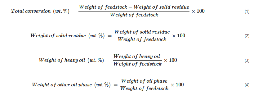
The product yield is calculated based on the way different products are collected. Some of the calculations can be generalized as shown below:
In cases where the weight of the gaseous product is measured, its percentage is simply calculated as
[20][72]:
In cases where it is not practical to record the weight of the gas phase, its weight fraction is calculated using the difference between reactor loading and recovered mixture weight:
 +1 credit