 +1 credit
| Version | Summary | Created by | Modification | Content Size | Created at | Operation |
|---|---|---|---|---|---|---|
| 1 | Ning Cai | + 2569 word(s) | 2569 | 2021-06-02 08:18:37 | | | |
| 2 | Karina Chen | Meta information modification | 2569 | 2021-06-16 06:15:27 | | |
Video Upload Options
MOFs are synthesized by the incorporation of both inorganic and organic units through template-guided assembly (e.g., mesh synthesis). The design flexibility of MOF in terms of highly variable geometry and functionality based on the choices of incorporated constituents has attracted increasing attentions from researchers in catalysis, energy, and electronics. The main advantage of MOFs in comparison with conventional porous materials is the achievement of specific structure and tunable porosity at the molecular level by adjusting both metal species and organic ligands. For instance, the typical porosity of MOFs is higher than 50% of the total solid volume while the surface area of MOFs generally ranges from 1000 to 10,000 m2 g−1, both superior to those found in conventional porous materials such as carbons and molecular sieve.
1. MOFs-Derived Nanofibers via Electrospinning
1.1. ZIFs/Electrospun Nanofibers (Z-NFs)
Zeolitic imidazolate frameworks (ZIFs) are a typical class of MOFs characterized by its porous crystalline structure extending into 3D space by bridging each tetrahedral metal ion with multiple imidazolate (Im) groups. Due to the flexibility of metal ions and organic blocks, the structure and properties of zeolites can be forged with interesting properties for challenging applications in molecular catalysis and separation [1]. As such, ZIFs have become the preferred material for preparing M-NFs based on relatively its simple synthesis, design flexibility, and structural specificity. The preparations and applications of M-NFs have been extensively studied in recent years [2][3][4][5][6][7][8][9]. At present, there are two main methods for preparing M-NFs:
(I) In situ growth method by preparing electrospun nanofibers that are incorporated with contain metal ions (or ligands), followed by in situ growth of MOF nanoparticles on electrospun nanofibers;
(II) Co-electrospinning synthesis by mixing MOF nanoparticles with a polymer solution to form a precursor followed by formation of M-NFs via electrospinning.
First of all, the preparation of zeolitic imidazolate framework-8 (ZIF-8)/polyacrylonitrile (PAN) nanofibers is introduced as a model M-NFs by in situ growth method (Ⅰ) was highlighted [2]. Specifically, as depicted in Figure 1a, zinc acetylacetonate (Zn(acac)2), PAN, and poly-(vinylpyrrolidone) (PVP) are mixed in N,N-Dimethylformamide (DMF) to obtain an electrospun precursor solution. Then Zn(acac)2/PVP/PAN fibers are prepared by electrospinning immediately followed by immersion in mixed with 2-methylimidazole (mIM) solution within a Teflon-lined container and kept at 120 °C for 12 hours. Because PVP is more hydrophilic than PAN, PVP can be extracted from Zn(acac)2/PVP/PAN fibers in accompany by the generation of pore structure by hydrothermal treatment (Figure 1b). It was shown that ZIF-8 nanocrystals grow tightly on the surface of PAN nanofibers. The mesoporous structure of in situ-ZIF-8/PAN is displayed on the surface of nanofibers during in situ growth process, which may be attributed to the removal of PVP (Figure 1c). Interestingly, a typical behavior of type IV hysteresis loop as shown in Figure 1e validates the existence of mesopores on ZIF-8/PAN fibers. Recently, mIM/PAN nanofibers have been prepared by electrospinning and subsequent chelating with Zn2+ ions provided by zinc acetate, leading to the formation of core–shell PAN@ZIF-8 [10]. Addition of mIM and zinc acetate solution during in situ growth can promote the further growth of ZIF-8 nanocrystals. Moreover, the core–shell structure of the composite displays high toughness due to the support of underlying PAN nanofibers. With regard to the in situ growth method in obtaining Z-NFs, organic ligand/polymer NFs or metal ion/polymer NFs are prepared first, and then the ZIFs crystal grows on the respective NFs.
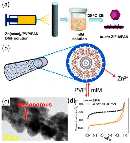
Figure 1. (a) The schematic diagram of in situ growth of ZIF-8 on PAN; (b) The formation mechanism of in situ ZIF-8/PAN fibers; (c) TEM patterns of the in situ-ZIF-8/PAN; (d) The N2 adsorption and desorption measurements of in situ-ZIF-8/PAN and ZIF-8. Reproduced from [2], with permission from American Chemical Society, 2018.
Apart from in situ-grown ZIF-8/PAN, other types of Z-NFs prepared have been prepared by in situ growth method. Zhou and co-workers reported the first time in situ crystal growth of ZIF-8 on electrospun polyurethane (PU) nanofibers (ZIF-8/PU) [9]. More specifically, the surface of PU nanofibers were roughened by the treatment with concentrated sulfuric acid and chromic anhydride, exposing more binding sites on the nanofiber surface. For instance, the emergence of anionic groups on the surface of PU nanofiber facilitates the adsorption of Zn2+, which serves as the coordination center of the ZIF-8 nanocrystal to be eventually distributed in high concentration on the PU nanofibers. Moreover, BET surface area of ZIF-8/PU decreases with the amount of ZIF-8 nanocrystal. Although the loading of the MOFs nanoparticles was increased by activating the surface of the fiber and the like, which brought about an occlusion of the pores and attenuate the adverse effects of the one-dimensional morphology of the nanofibers. Therefore, it is not advisable to increase the load blindly, various factors such as the ‘bearing capacity of the nanofibers’ should be comprehensively considered in the preparation of M-NFs.
In addition to pre-treating the materials during in-situ growth to optimize the structure of the M-NFs, different metal sources can also be used to obtain different structures and performances. Different types of materials can be selected as the source of metal ions or as templates for the growth of ZIFs crystal. By introducing other materials into the crystal growth process, a variety of composites with unique structures and physical properties can be obtained. Activation of the fiber surface and continued addition of ligand or metal ion solution during in situ growth can promote the ZIFs crystal growth. When In2O3/ZnO2 nanofibers instead of Zn2+ coated PU nanofiber was applied as a source of Zn2+ for serving as a template for the in situ growth of ZIF-8, an In2O3/ZIF-8 core–shell complex was successfully produced with the effective loading of ZIF-8. It is also noteworthy that the transformation from ZnO particles to metal centers coordinated with organic ligands may likely lead to the formation of structural defects between linkers, thus enlarging the pore size of metal–organic framework ZIF-8 [11][12]. In addition, the transformation as mentioned above can cause ZIF-8 to form multiple pore structures.
While the in situ growth method is being developed, another method known co-electrospinning has received increasing attentions. Again, ZIF-67/PAN is used as a typical example to cover the co-electrospinning method in detail [13]. Schematic diagram, TEM image and the corresponding elemental mapping of ZIF-67/PAN as shown in Figure 2. After the synthesis of ZIF-67 nanoparticles, the nanoparticles were mixed with PAN to form an electrospun precursor solution and ZIF-67/PAN nanofiber was fabricated by electrospinning. When the ZIF-67/PAN are applied to the catalytic degradation of pollutants, the high specific surface area of the ZIF/PAN can promote effective contact between active sites and pollutants. Random arrays and macroscopic materials with continuous specific surface area and flexibility are also promotive to the recovery and reuse of catalysts [14]. In addition to the most common only used PAN and PVP, the use of other polymers such as polyethylene oxide (PEO) and polystyrene (PS) has improved the fiber stability and expanded the range of possible applications. Previously, Smarsly and co-workers have reported on ZIF-8/PVP nanofibers, which was prepared by co-electrospinning [8]. Table 1 lists the BET surface area of the nanofibers formed by the combination of ZIF-8 and different types of polymer. The co-electrospinning method enables ZIFs nanoparticles to be uniformly loaded on electrospun fibers. It is worth noting that the co-electrospinning method imposes design constraints on the selection of ZIFs within a specific range of size. If ZIFs is too large compared to the electrospun fibers with dimension of several hundred nanometers, it would result in the ineffective encapsulation of ZIF by the electrospun fiber matrix and nonuniform dispersion of the particles on the fiber matrix. Comparatively, the ZIFs particles with appropriate size would be evenly dispersed in the electrospun solution before electrospinning to ensure uniform loading of the particles on electrospun fibers. Regardless of the method route of synthesis of the Z-NFs, it has the following characteristics in general:
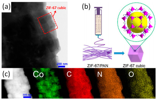
Figure 2. (a) TEM image of ZIF-67/PAN; (b) Preparation schematic of ZIF-67/PAN; (c) STEM image and the corresponding elemental mapping of ZIF-67/PAN. Reproduced from [13], with permission from Elsevier, 2017.
-
(a)
-
ZIFs nanoparticles are evenly loaded in the fiber matrix and the degree of loading is adjustable, which effectively avoid the large-scale agglomeration of ZIFs nanoparticles;
-
(b)
-
Defects, mesopores, etc. can be formed during electrospinning;
-
(c)
-
Nanofibers can enhance the mechanical properties and stability of Z-NFs due to its support and protection of ZIFs nanoparticles.
1.2. Other Types of M-NFs
Z-NFs is not only the most representative type of material in M-NFs, but also the earliest and most widely studied materials. With the development of Z-NFs, more MOF materials other than sole ZIFs have been produced through the fabrication of nanofiber composites by electrospinning (in the rest of the article, M-NFs only refers to other types of M-NFs except Z-NFs). M-NFs are prepared in a similar way compared to Z-NFs, while larger range of structural and physical properties of M-NFs are revealed, due to the significant variability among different metal centers and organic ligands [15][16][17][18][19][20][21][22].
The preparation methods of ZIFs are simple and the preparation conditions are mild. However, the preparation conditions of MOFs such as HKUST-1 are complicated. Thus, the preparation of such M-NFs has a variety of methods. For instance, Wang and co-workers have prepared a new type of M-NFs known as HKUST-1 (Cu-MOF)/PAN nanofibers by combining co-electrospinning and in situ growth, which promoted multiple growth and activation processes [15]. The active site of CO2 adsorption on the HKUST-1/PAN nanofibers are mainly at the open metal sites (Figure 3a). The as-synthesized HKUST-1 particles and HKUST-1/PAN NFs readily exhibits polydisperse microporous characteristics (Figure 3b). As shown in Figure 3c, the BET surface area of the HKUST-1/PAN NFs increase significantly due to the increase of the loading of HKUST-1 nanoparticles after three times of growth and activation. Interestingly, the multiple growth and activation processes during the preparation of HKUST-1/PAN nanofibers with high HKUST-1 can promote the effective integration between coordinated unsaturated metal sites and uncoordinated –COO- within frameworks [23]. In addition, the membranous HKUST-1/PAN nanofibers solves the problem of pipeline blocking and recovery inefficiency during the adsorption process as the nanofiber is less susceptible to powder and display less tendency to form agglomerate [24][25].
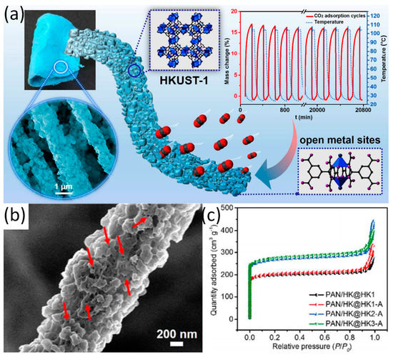
Figure 3. (a) Overview of HKUST-1/PAN and adsorption of CO2; (b) SEM image with higher magnification of the HKUST-1/PAN nanofiber; (c) N2 adsorption–desorption isotherms of samples with different growth times. Reproduced form [15], with permission from American Chemical Society, 2017.
Multiple activations and growths can enhance the loading of MOF nanoparticles and the binding force of MOF particles and nanofibers to obtain more stable and more active composites. Besides, similar performance can be achieved by selecting the appropriate polymer with a target group which can form a strong bonding with the organic functional groups or ions in MOFs. Recently, Peng and co-workers have reported a UiO-66/PVA (polyvinyl alcohol) nanofiber networks via co-electrospinning [16]. The hydroxyl groups (-OH) in PVA and the carboxylic acid groups (-COOH) in UiO-66 could be esterified during the electrospinning process to form ester bonds, which facilitates the formation of interwoven nanofiber networks. Moreover, the nanofiber networks can improve the wettability of materials in the electrolytes when it is applied as battery materials [26]. It is tough to fabricate independent MOF–organic matrix composites with high MOF-loading capacity by general preparation method. Recently, Wu et al. have reported the fabrications of HKUST-1/PS (polystyrene) and MIL-101(Fe)/PS via co-electrospinning when most MOF particles are encapsulated within the fibers during electrospinning [17]. Only when MOF particles with high loading enough are exposed to the surface of the fibers, the carrying of gas and the transfer of electron can be facilitated for the materials. However, adding high load of MOF particles will reduce the suitability of polymer solutions for use in electrospinning. In addition, with the increase of MOF loading during electrospinning, it is difficult to obtain compact and continuous MOF films. By using MOF-doped electrospun nanofibers as the skeletal backbone, the growth of second MOF layer on the fibers can overcome the existing difficulties [17]. In short, the problems of preparing M-NFs can be resolved by a combination of co-electrospinning and in situ growth.
The polymers related to M-NFs which were reported in recent years are mainly PAN, PVP, PVA, PS, etc. However, many other polymers (such as PVDF, PA, PEO, etc.) are also important materials for preparing M-NFs. Laurila et al. reported the in situ crystal growth of HKUST-1 on electrospun cellulose nanofibers [27]. Yang et al. also reported on a composite material, which was composed of cellulose paper and MOF-5 (Zn3(BDC)2) metal organic frameworks (paper@MOF-5) materials [28]. Zhao et al. reported that TiO2 coatings deposited on polyamide-6 (PA-6) nanofibers by atomic layer deposition (ALD) to form Zr-based MOF thin films (PA-6@TiO2@UiO-66-NH2). Moreover, certain MOF–nanofiber textile composites can achieve ultra-fast degradation of chemical warfare agents (CWAs) [29]. Wu et al. reported that electrospun nanofiber membrane composed of MOFs and SPPESK was applied in proton exchange membrane fuel cell [30]. Recently, Xu et al. reported on the application of ZIF-8 functionalized hierarchical micronanofiber membrane (PVDF-g-ZIF-8) in high-efficiency oil/water separation [4]. Rosal and co-workers presented polylactic acid (PLA) fibers containing cobalt-based MOF as a new class of antimicrobial film material [6]. Similarly, Shariatinia and co-workers reported on the synthesis of antimicrobial chitosan–polyethylene oxide (CS-PEO) nanofiber mats loaded with ZIF-8 NPs via electrospinning [31].
2. Electrospun MOFs-Derived Carbon Nanofibers
2.1. Synthesis
Electrospun MOFs-derived carbon nanofibers (M-CNFs) are generally prepared by heat treatment and reduction of M-NFs that obtained via electrospinning. After M-NFs are obtained, the heat treatment of composites can be roughly classified into two categories:
(I) The composites are directly subjected to high temperature carbonization under an air atmosphere to obtain a target product (direct calcination method). The structure and properties of the target product can be controlled by changing the temperature, heating rate, and calcination time.
(II) Preheating the composites in an air atmosphere at lower temperature and then transferring the composites to high temperature carbonization under N2 (or Ar) atmosphere (indirect calcination method).
In the direct calcination method, pure phase metal oxides can be obtained at higher temperatures. Recently, Kim and co-workers have reported that the as-spun Pd@ZIF-8/PVP/Sn composite NFs were transformed to PdO@ZnO-SnO2 NTs after the calcination at 600 °C for 1 h in air atmosphere under the heating rate of 10 °C min−1 [32]. Some polymer fibers (such as PAN) are easily decomposed at high temperatures, causing the damage to the fiber structure. Therefore, in the indirect calcination method, before the calcination of samples at high temperature, the samples are preheated and oxidized first to remove some heat-labile organic functional groups to ensure the integrity of the nanofiber network structure. For instance, Guo et al. reported the obtention of the Co/CoOx-N-C via the pyrolysis process that includes stabilization and carbonization. The progress of stabilization was implement in air at 280 °C for 2 h. Carbonization step was conducted in a N2 atmosphere at temperature up to 800 °C for 1 h [33].
2.2. Application
The wide application of M-CNFs is attributed to its attractive structures such as one-dimensional nanofibrous morphology and hollow tubular structure. MOFs-derived carbon nanofibers have been considered as excellent electrode materials in energy conversion and storage devices [34][35][36]. Moreover, catalysis and sensors are also the main applications of M-CNFs. Typical applications (e.g., battery, sensor, and electrocatalyst) of materials are presented and analyzed.
References
- Phan, A.; Doonan, C.J.; Uribe-Romo, F.J.; Knobler, C.B.; O’Keeffe, M.; Yaghi, O.M. Synthesis, Structure, and Carbon Dioxide Capture Properties of Zeolitic Imidazolate Frameworks. Acc. Chem. Res. 2010, 43, 58–67.
- Wang, C.; Zheng, T.; Luo, R.; Liu, C.; Zhang, M.; Li, J.; Sun, X.; Shen, J.; Han, W.; Wang, L. In Situ Growth of ZIF-8 on PAN Fibrous Filters for Highly Efficient U(VI) Removal. ACS Appl. Mater. Interfaces 2018, 10, 24164–24171.
- Liu, Y.; Wang, R.; Zhang, T.; Liu, S.; Fei, T. Zeolitic imidazolate framework-8 (ZIF-8)-coated In2O3 nanofibers as an efficient sensing material for ppb-level NO2 detection. J. Colloid Interface Sci. 2019, 541, 249–257.
- Xu, S.; Ren, L.-F.; Zhou, Q.; Bai, H.; Li, J.; Shao, J. Facile ZIF-8 functionalized hierarchical micronanofiber membrane for high-efficiency separation of water-in-oil emulsions. J. Appl. Polym. Sci. 2018, 135, 46462.
- Yang, W.; Liu, X.; Chen, L.; Liang, L.; Jia, J. A metal-organic framework devised Co-N doped carbon microsphere/nanofiber hybrid as a free-standing 3D oxygen catalyst. Chem. Commun. (Camb.) 2017, 53, 4034–4037.
- Quirós, J.; Boltes, K.; Aguado, S.; de Villoria, R.G.; Vilatela, J.J.; Rosal, R. Antimicrobial metal–organic frameworks incorporated into electrospun fibers. Chem. Eng. J. 2015, 262, 189–197.
- Bechelany, M.; Drobek, M.; Vallicari, C.; Abou Chaaya, A.; Julbe, A.; Miele, P. Highly crystalline MOF-based materials grown on electrospun nanofibers. Nanoscale 2015, 7, 5794–5802.
- Ostermann, R.; Cravillon, J.; Weidmann, C.; Wiebcke, M.; Smarsly, B.M. Metal-organic framework nanofibers via electrospinning. Chem. Commun. (Camb) 2011, 47, 442–444.
- Lian, Z.; Huimin, L.; Zhaofei, O. In situ crystal growth of zeolitic imidazolate frameworks (ZIF) on electrospun polyurethane nanofibers. Dalton Trans. 2014, 43, 6684–6688.
- Gao, M.; Zeng, L.; Nie, J.; Ma, G. Polymer–metal–organic framework core–shell framework nanofibers via electrospinning and their gas adsorption activities. RSC Adv. 2016, 6, 7078–7085.
- Morabito, J.V.; Chou, L.Y.; Li, Z.; Manna, C.M.; Petroff, C.A.; Kyada, R.J.; Palomba, J.M.; Byers, J.A.; Tsung, C.K. Molecular encapsulation beyond the aperture size limit through dissociative linker exchange in metal-organic framework crystals. J. Am. Chem. Soc. 2014, 136, 12540–12543.
- Xu, P.; Xu, T.; Yu, H.; Li, X. Resonant-Gravimetric Identification of Competitive Adsorption of Environmental Molecules. Anal. Chem. 2017, 89, 7031–7037.
- Wang, C.; Wang, H.; Luo, R.; Liu, C.; Li, J.; Sun, X.; Shen, J.; Han, W.; Wang, L. Metal-organic framework one-dimensional fibers as efficient catalysts for activating peroxymonosulfate. Chem. Eng. J. 2017, 330, 262–271.
- Chou, Y.; Shao, C.; Li, X.; Su, C.; Xu, H.; Zhang, M.; Zhang, P.; Zhang, X.; Liu, Y. BiOCl nanosheets immobilized on electrospun polyacrylonitrile nanofibers with high photocatalytic activity and reusable property. Appl. Surf. Sci. 2013, 285, 509–516.
- Zhang, Y.; Zhang, Y.; Wang, X.; Yu, J.; Ding, B. Ultrahigh Metal-Organic Framework Loading and Flexible Nanofibrous Membranes for Efficient CO2 Capture with Long-Term, Ultrastable Recyclability. ACS Appl. Mater. Interfaces 2018, 10, 34802–34810.
- Zhang, C.; Shen, L.; Shen, J.; Liu, F.; Chen, G.; Tao, R.; Ma, S.; Peng, Y.; Lu, Y. Anion-Sorbent Composite Separators for High-Rate Lithium-Ion Batteries. Adv. Mater. 2019, 31, e1808338.
- Wu, Y.-N.; Li, F.; Liu, H.; Zhu, W.; Teng, M.; Jiang, Y.; Li, W.; Xu, D.; He, D.; Hannam, P.; et al. Electrospun fibrous mats as skeletons to produce free-standing MOF membranes. J. Mater. Chem. 2012, 22, 16971–16978.
- Peterson, G.W.; Lu, A.X.; Epps, T.H., III. Tuning the Morphology and Activity of Electrospun Polystyrene/UiO-66-NH2 Metal-Organic Framework Composites to Enhance Chemical Warfare Agent Removal. ACS Appl. Mater. Interfaces 2017, 9, 32248–32254.
- Lu, A.X.; McEntee, M.; Browe, M.A.; Hall, M.G.; DeCoste, J.B.; Peterson, G.W. MOFabric: Electrospun Nanofiber Mats from PVDF/UiO-66-NH2 for Chemical Protection and Decontamination. ACS Appl. Mater. Interfaces 2017, 9, 13632–13636.
- Leus, K.; Krishnaraj, C.; Verhoeven, L.; Cremers, V.; Dendooven, J.; Ramachandran, R.K.; Dubruel, P.; Van Der Voort, P. Catalytic carpets: @electrospun PCL, a surprisingly active and robust hydrogenation catalyst. J. Catal. 2018, 360, 81–88.
- Ismail, F.M.; Abdellah, A.M.; Ali, P.A.; Shawky, S.M.; Alkordi, M.H.; El-Sherbiny, I.M. Bilayer sandwich-like membranes of metal organic frameworks-electrospun polymeric nanofibers via SiO2 nanoparticles seeding. Mater. Today Commun. 2017, 12, 119–124.
- Efome, J.E.; Rana, D.; Matsuura, T.; Lan, C.Q. Insight Studies on Metal-Organic Framework Nanofibrous Membrane Adsorption and Activation for Heavy Metal Ions Removal from Aqueous Solution. ACS Appl. Mater. Interfaces 2018, 10, 18619–18629.
- Yan, X.; Komarneni, S.; Zhang, Z.; Yan, Z. Extremely enhanced CO2 uptake by HKUST-1 metal–organic framework via a simple chemical treatment. Microporous Mesoporous Mater. 2014, 183, 69–73.
- Zhang, Y.; Yuan, S.; Feng, X.; Li, H.; Zhou, J.; Wang, B. Preparation of Nanofibrous Metal-Organic Framework Filters for Efficient Air Pollution Control. J. Am. Chem. Soc. 2016, 138, 5785–5788.
- Zhang, Y.; Guan, J.; Wang, X.; Yu, J.; Ding, B. Balsam-Pear-Skin-Like Porous Polyacrylonitrile Nanofibrous Membranes Grafted with Polyethyleneimine for Postcombustion CO2 Capture. ACS Appl. Mater. Interfaces 2017, 9, 41087–41098.
- Zhang, W.; Tu, Z.; Qian, J.; Choudhury, S.; Archer, L.A.; Lu, Y. Design Principles of Functional Polymer Separators for High-Energy, Metal-Based Batteries. Small 2018, 14, e1703001.
- Laurila, E.; Thunberg, J.; Argent, S.P.; Champness, N.R.; Zacharias, S.; Westman, G.; Öhrström, L. Enhanced Synthesis of Metal-Organic Frameworks on the Surface of Electrospun Cellulose Nanofibers. Adv. Eng. Mater. 2015, 17, 1282–1286.
- Yang, Q.; Zhang, M.; Song, S.; Yang, B. Surface modification of PCC filled cellulose paper by MOF-5 (Zn3(BDC)2) metal-organic frameworks for use as soft gas adsorption composite materials. Cellulose 2017, 24, 3051–3060.
- Zhao, J.; Lee, D.T.; Yaga, R.W.; Hall, M.G.; Barton, H.F.; Woodward, I.R.; Oldham, C.J.; Walls, H.J.; Peterson, G.W.; Parsons, G.N. Ultra-Fast Degradation of Chemical Warfare Agents Using MOF–Nanofiber Kebabs. Angew. Chem. Int. Ed. 2016, 55, 13224–13228.
- Wu, B.; Pan, J.; Ge, L.; Wu, L.; Wang, H.; Xu, T. Oriented MOF-polymer composite nanofiber membranes for high proton conductivity at high temperature and anhydrous condition. Sci. Rep. 2014, 4, 4334.
- Kohsari, I.; Shariatinia, Z.; Pourmortazavi, S.M. Antibacterial electrospun chitosan-polyethylene oxide nanocomposite mats containing ZIF-8 nanoparticles. Int. J. Biol. Macromol. 2016, 91, 778–788.
- Koo, W.-T.; Jang, J.-S.; Choi, S.-J.; Cho, H.-J.; Kim, I.-D. Metal–organic framework templated catalysts: Dual sensitization of PdO–ZnO composite on hollow SnO2 nanotubes for selective acetone sensors. ACS Appl. Mater. Interfaces 2017, 9, 18069–18077.
- Guo, J.; Chen, B.; Hao, Q.; Nie, J.; Ma, G. Pod-like structured Co/CoOx nitrogen-doped carbon fibers as efficient oxygen reduction reaction electrocatalysts for Zn-air battery. Appl. Surf. Sci. 2018, 456, 959–966.
- Chen, Y.M.; Yu, L.; Lou, X.W. Hierarchical Tubular Structures Composed of Co3O4 Hollow Nanoparticles and Carbon Nanotubes for Lithium Storage. Angew. Chem. Int. Ed. Engl. 2016, 55, 5990–5993.
- Eftekhari, A.; Kim, D.-W. Cathode materials for lithium–sulfur batteries: A practical perspective. J. Mater. Chem. A 2017, 5, 17734–17776.
- Elazari, R.; Salitra, G.; Garsuch, A.; Panchenko, A.; Aurbach, D. Sulfur-impregnated activated carbon fiber cloth as a binder-free cathode for rechargeable Li-S batteries. Adv. Mater. 2011, 23, 5641–5644.


