 +1 credit
| Version | Summary | Created by | Modification | Content Size | Created at | Operation |
|---|---|---|---|---|---|---|
| 1 | Riley Carriere | + 6529 word(s) | 6529 | 2021-05-04 10:33:02 | | | |
| 2 | Conner Chen | -85 word(s) | 6444 | 2021-05-12 12:26:21 | | |
Video Upload Options
Sandwich panels are widely used in the design of unmanned satellites and, in addition to having a structural function, can often serve as shielding, protecting the satellites’ equipment from hypervelocity impacts (HVI) of orbital debris and micrometeoroids.
1. Satellite Sandwich Structures
To ensure mission success goals, Earth satellites must be analyzed for their ability to survive hypervelocity impacts (HVI) by orbital debris, because collision of a functional satellite with even a millimeter-sized object traveling at typical orbital speed (7 km/s and higher) can be detrimental for both the spacecraft and Earth’s orbit environment [1]. Consequences may include loss-of-spacecraft failures owing to the damage of components vital for satellite functioning (e.g., electronics units or connecting cables), as well as the bursting of pressurized containers, such as satellite propellant tanks. In turn, this can cause multibillion-dollar financial losses for spacecraft owners and significant negative impacts on Earth’s orbit environment due to the generation of new orbital debris. To avoid such scenarios, orbital debris impact survivability must be analyzed during the early stages of satellite design, when initial structural sizing is being performed [2].
Efforts to design lightweight orbital debris shields have been mainly driven by the need to protect habitable modules of the International Space Station [3][4][5][6], which were designed as pressurized thin-walled structures with limited ability to absorb and dissipate the energy of hypervelocity projectiles. Accordingly, they are equipped with single-purpose shielding. Protective properties of such single-purpose shields as the Whipple (dual wall) shield [7][8], stuffed Whipple [9][10], and multiwall shield [8] were extensively investigated. Based on these studies, manufacturers have developed and adopted ballistic limit equations (BLEs)—empirical response surface models linking either critical projectile diameter that can cause shield perforation with the impact conditions (projectile speed and material) and shield design parameters (so-called “performance BLEs”), or the required shield parameters to ensure no-perforation for the given projectile diameter and impact conditions (so-called “design BLEs”) [10][11][12][13].
Structures of unmanned (robotic) satellites, however, are usually different from manned spacecraft, and it is often possible to use multifunctional design strategies for greater weight efficiency instead of the single-purpose shielding [14]. In a typical satellite design (e.g., CASSIOPEE, RADARSAT, Terra, GOCE, BeppoSAX satellites, etc.), most impact-sensitive equipment is situated in the enclosure of the structural sandwich panels. The most commonly used elements of satellite structures, these panels form the satellite’s shape and are primarily designed to resist launch loads and provide attachment points for satellite subsystems [15]. With low additional weight penalties, their intrinsic ballistic performance can often be upgraded to the level required for orbital debris protection [16]. Perforation of a satellite structural panel can be considered as a failure criterion, because otherwise unprotected components (e.g., circuit boards, cables, etc.) and components that are highly vulnerable to orbital debris impacts (e.g., pressurized propellant tanks) may be rendered non-functional post-impact. Assessing the orbital debris impact survivability of robotic satellites requires HVI testing or reliable BLEs (or other predictive models) for sandwich panels, capable of accounting for various impact conditions and design parameters, including, but not limited to projectile material and shape, material of the facesheets, and type and geometric parameters of the panel’s core.
For the projectile materials, the engineering orbital debris model ORDEM 3.0, developed by NASA [17], breaks down the debris population into three categories according to the type of material, namely low- (plastics), medium- (aluminium) and high-density (steel and copper) classes. Although the medium-density fragments traditionally dominate the overall debris population, it is also important for the safety of spacecraft to ensure satisfaction of the design constraints in case of impacts by the other debris classes. The objective of this review paper with respect to projectile materials is to determine if the existing predictive models for sandwich panels were built using sufficient experimental data to be applicable to low-, medium- and high-density projectile material classes.
Projectile geometries vary in Earth’s orbital environment and differ from symmetrical simple geometries seen in experimentation. Historically, predictive models have taken advantage of spherical projectiles due to the ease of experimentation, and replication and for simplification in modelling; although expansions to non-uniform shapes have been simulated. This study will investigate and discuss the applicability of sandwich panels’ BLEs for different projectile shapes, as well as the sufficiency of the corresponding experimental data to validate them.
Facesheet materials used in sandwich structure design may consist of multiple lightweight materials and associated combinations, with preference given towards low-density alloys and polymers. In addition, multi-layer insulation (MLI) may serve as a preliminary barrier of protection. The validity of existing predictive models will be reviewed for different facesheet materials and material combinations.
Core materials: cost effective debris shields traditionally possess honeycomb-cores, characterized by core thickness, areal density, cell wall (foil) thickness and cell size [18]. Honeycomb core materials are commonly variations of aluminium alloy, Nomex®, Nextel, Kevlar, glass- and/or carbon-fibre [19][20]. Developments have shown promise in metallic open-cell foam cores, typically composed of aluminium alloy or titanium [21]. Open-cell foam cores are characterized by core thickness, pore density (measured by number of pores per inch, PPI) and foam relative density. Honeycomb- and foam-core spacecraft sandwich structures are schematically represented in Figure 1, which details the thicknesses of the facesheets (tf) and core thickness (S).
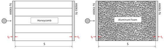
Figure 1. Schematic of single honeycomb-core (left) and foam-core (right) panels.
2. Honeycomb-Core Sandwich Panels (HCSP)
2.1. Experimental Studies
Shielding applications are typically concerned with micro-meteoroids and orbital debris less than 1 cm in size, which cannot be tracked nor avoided with pre-determined avoidance measures [22] and dominate the orbital debris population. Single-purpose shields include monolithic shielding (simply a singular facesheet), Whipple shields (consist of two facesheets separated by spacing), and its variations (Whipple shield with flexible stuffing; multi-wall shields). An additional facesheet possessed by a Whipple shield warrants higher damage tolerance and weight efficiency than that of monolithic shielding [23]. Honeycomb-core sandwich shields were developed as an alternative to the single-purpose protective systems [24]. Similarly to the Whipple design, a honeycomb-core sandwich panel possesses two facesheets, but attached to a honeycomb-core. HCSPs are pre-available on many spacecraft, serving functions such as load-bearing structures, and upgrading their ballistic performance for debris protection warrants weight reduction by removing the need for additional external shielding installment [16].
2.1.1. Channeling Effect of Honeycomb
Honeycomb-core shielding incurs a channeling effect on the debris cloud as a result of the hexagonal cell structure which limits the radial expansion of the debris cloud post-fragmentation [24]. Since channeled, an adverse effect is the increased concentrated areal damage on the rear facesheet, reducing the shielding effectiveness as compared to that of a Whipple shield configuration, where post-fragmentation damage is spread radially due to expansion of the fragment cloud [25]. These effects are illustrated in Figure 2. Here, the debris cloud expands freely throughout the Whipple shield spacing (void) but is inhibited in the honeycomb cells, as cell walls provide resistance to projectile fragments [26]. Taylor et al. concluded this reduction in protective capability for honeycomb-core structures in comparison to a Whipple shield, as a result of forty-two honeycomb-core HVI tests. Honeycomb-core test data were then viewed versus the modified Cours-Palais Whipple Shield ballistic limit curve with which comparisons were drawn [25][27][28].
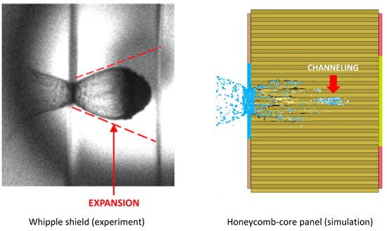
Figure 2. Propagation of fragment cloud in between the front and rear walls of a Whipple shield (left) and a honeycomb-core sandwich panel (right) after 7 km/s sub-centimeter projectile impact. Effects of fragment cloud expansion and channeling are clearly visible.
2.1.2. Effect of Multi-Layer Insulation (MLI)
Multi-layer insulation and its constituents serve two distinct purposes: to maintain a suitable thermal climate for equipment and improve the protective performance of satellite structures [19]. When MLI is applied on top of satellite sandwich panels, it serves as an additional protective layer, enhancing disruption of a projectile. Variations of MLI include enhanced and toughened multi-layer insulation (EMLI and TMLI, respectively). EMLI is constructed by introducing Kevlar and beta cloth—woven silica fibers—as additives to standard MLI, whereas TMLI is constructed solely with additional layers of beta cloth. EMLI and TMLI provide improved protection compared to standard MLI. This was confirmed experimentally by Lambert et al., who compared honeycomb-core samples from five distinct satellite structures and demonstrated that higher kinetic energy was required to perforate panels protected by TMLI and EMLI than those protected by standard multilayer insulation [23].
2.1.3. Effect of Facesheet Material
Carbon fiber-reinforced plastics (CFRP) are extensively used in the design of satellite sandwich structures to improve their weight efficiency [23][29]. CFRP facesheets are common practice, coupled with an aluminium (Al) honeycomb core, in satellite design with use noted in the GOCE, Radarsat2, Hershcel/Plank, Integral and BeppoSAX satellites [29][30]. With respect to CFRP facesheets, Ryan et al. predicted lower Hugoniot pressures when struck with a spherical Al projectile than that witnessed by Al facesheets at equivalent velocities [30]. Impact velocities required for the onset of projectile fragmentation (shattering) and the onset of projectile melting in the case of impacts on CFRP targets were higher than those of Al targets. In particular, for Al projectile–CFRP target impacts, projectile shattering and melting initiated at 4.2 km/s and 8.4 km/s, respectively, while for Al–Al impacts, the corresponding velocities were 3 km/s and 7 km/s.
Hypervelocity impact experimentation of CFRP/Al honeycomb-core sandwich panels have noted ample testing in literature [23][25][27][28][29][30][31][32]. Taylor et al. documented forty-two preliminary experimentations of CFRP/Al HCSP [25][27][28]. Impact incident angles of 0°, 15°, 30°, 45°, 60° and 75° were investigated in a velocity range of 4.5 km/s to 6.2 km/s. Lambert, Schäfer and Geyer performed five tests on CFRP/Al honeycomb-core sandwich panels samples, representative of the Envisat earth observation satellite [23]. Testing included projectile diameters of 0.9–1.5 mm, and velocities of 5.3–6.6 km/s for only normal incident impacts. Ryan et al. investigated the ballistic performance of six representative CFRP/Al honeycomb-panels (GOCE, Radarsat2, Hershcel/Plank and BeppoSAX configurations) [30]. Fifty-five impact tests were commissioned in the test program: velocities ranging between 2.02–7.75 km/s, impact incident angles of 0°, 45° and 60°, and spherical aluminium projectile diameter between 0.0761–5 mm. This expanded upon testing conducted by from Ryan, Schäefer and Riedel and Ryan et al., who performed thirty-eight HVI experiments, representing structure configurations from the Radarsat-1, Radarsat-2, Radarsat-3, GOCE and BeppoSAX [29][31]. Spherical aluminium projectiles were used, with diameters up to and including 0.5–2.0 mm. The velocity range was 2.02–6.62 km/s for incident impact angles of 0°, 45° and 60° [29]. A comparative analysis was performed using the normalized ballistic protection capability (NBPC), the ratio of the critical projectile diameter to areal weight of the shielding sample. Resulting ranges were plotted, concluding that the Radarsat-2, Radarsat-3, GOCE and BeppoSAX samples produced similar NBPC; however, Radarsat-1 significantly underperformed in comparison and is believed to be the result of the Radarsat-1 configuration having a much thicker honeycomb-core.
2.1.4. Effect of Honeycomb Material
Historically, honeycomb-core materials have seen vast usage of Al compositions, however materials such as Nomex®, Nextel and Kevlar are potential inclusions [19]. Nextel and Kevlar materials are used as intermediate facesheet materials in multi-wall shielding types to further increase protective capability. Ryan and Christiansen investigated three honeycomb-core configurations, namely 2.0-inch-thick Nomex, 1.0-inch-thick Trussgrid, and standard 2.0-inch-thick Al-honeycomb. Nomex® is a non-metallic honeycomb structure which capitalizes on the use of aramid-fibres, prized for its lower surface hardness and resulting higher ricochet angle. Sample cores were 5.08 cm thick with a total areal density of 1.10 g/cm3. Trussgrid® is defined as a three-dimensional honeycomb composed of cross-laminated Al foil, used to enhance energy absorption. Samples possessed a 2.54 cm thick core and an areal density of 0.74 g/cm3. Standard 2.0 inch Al samples were composed of 5.08 cm cores possessing a total areal density of 1.43 g/cm3. Testing encompassed impact velocities ranging between 2–6 km/s, 0° and 60° impact angle and spherical Al projectile diameters between 2–6 mm. In comparison to the standard 2.0 inch Al-honeycomb, testing concluded that the Trussgrid samples were superior because perforations were prevented, whereas Nomex samples exhibited poorer results compared that of the Al-cores. Significant changes in debris cloud nature were observed in the Nomex sample; lateral extension was increased, resulting in a lessening of the channeling effect. This reduction did not translate to an improvement of shielding capability; increased areal damage to the rear facesheet was noted.
Earlier experimentation by Yasensky and Christiansen investigated the performance of Al and titanium honeycomb core sandwich panel structures [21]. Testing incorporated 0.5 inch and 2.0 inch Al and 0.5-inch-thick titanium-cores, possessing panel areal densities of 0.37 g/cm2, 1.59 g/cm2, and 0.93 g/cm2, respectively. The experimental program used spherical Al projectiles ranging between 0.8–3.6 mm in diameter and impact velocities between 6.22–6.99 km/s for incident angles of 0°, 45°, and 60°. As was deduced from the tests conducted with 0.5 inch cores, panels with titanium core and titanium facesheets could tolerate normal impacts of larger-size projectiles than all-aluminium panels. An increase in the projectile critical diameter by approximately a factor of 1.8 and its mass by a factor of 5.5 due to the use of titanium was accompanied by an increase in the panel’s areal weight by approximately a factor of 2.5. It is, however, believed by the authors of this review that the observed improvement of the ballistic performance can be mainly attributed to the use of titanium facesheets rather than the use of titanium core in the tested panels.
2.1.5. Effect of Projectile Material
As a variety of materials used in spacecraft design have increased over the years, so did the composition of orbital debris population, and the projectile materials considered when designing orbital debris shielding should be expanded. By introducing materials such as graphite, nylon, glass, and steel into low-earth orbit, the ratios of, low-, medium- and high-density micrometeoroid debris have shifted. This is especially true for CFRP, because usage increase resulted in more CFRP fragments due to mission-related debris and fragmentation debris generated by collisions and explosions in Earth’s orbit [33]. Predominantly, medium-density Al projectiles were tested—experimentally and numerically—due to its widespread usage [18][21][23][24][30][31][34][35][36][37][38][39][40][41][42]. Testing of low- (plastics) and high-density (steel and copper) projectile materials are scarcer, however some experimentation on graphite, nylon, glass, and steel has been performed [20][25][27][28][33][43].
Taylor et al. documented forty-two HVI experimentations with nylon, aluminium, titanium and various steel projectiles possessing diameters of 0.8–6.2 mm [25][27][28]. Of the forty-two experiments, a subset of twenty-eight shots consisting of 1.2–1.5 mm Al, 1.2 mm titanium and 1.0 mm steel spherical projectiles were investigated to compare impact energies and blast damage to the HCSP structure. A strong dependence of the ballistic limit on projectile density was identified.
A comprehensive HVI database was constructed by Hyde et al. for the Orbiter shuttle program. Factors investigated included projectile material and dimensions, impact location, and damage characterization (where applicable, inside and outside hole diameter(s) on thermal tape and facesheets, facesheet damage type and facesheet crater depth and diameter(s)) [20]. Experimentation allowed for extensive categorization of payload bay door radiators, for which 65 tests were performed using spherical projectiles of glass, Al, aluminium oxide and stainless steel. With respect to post-impact damage characterization, glass projectiles resulted in facesheet cratering, whereas higher density materials such as Al, aluminium oxide and stainless-steel projectiles predominately perforated the facesheet. For similar projectile diameters, stainless steel possessed larger perforations (inner hole diameters) than aluminium oxide and even more so than aluminium projectiles.
2.1.6. Effect of Projectile Geometry
Commonly, BLE and predictive models are developed under the premise of using spherical projectiles to set a characteristic dimension—a sphere’s diameter—however, in reality, fragments can possess various geometries. Programs such as the DebriSat hypervelocity experiment have identified the need to study alternative projectile geometries, employing the use of cylindrical projectiles which inherently have a dependence on the angle of attack (AOA) [33][43]. By verifying numerical simulations to experimental results, a wide variety of impact obliquities and projectile orientations were investigated. It was concluded that the critical dimension, critical length, could be composed of the projectiles’ diameter, pitch, and obliquity. Projectile geometries representative of a rod and disk were compared. When the critical mass of the spherical projectile exceeded that of the cylindrical projectiles, rod geometries possessing low pitch and disk geometries possessing high pitch warranted critical impact. The Debrisat HVI program studied Whipple shields only, however similar effects may be characteristic for sandwich panel structures.
Prior to the DebriSat experiments, Cours-Palais reviewed the effect of shape parameters on Whipple shields by analyzing HVI data from the literature [44][45][46][47]. The experimental data analyzed studied the effect of disk, plate, cylindrical, rod and jet projectile geometries with normal incidence loading conditions. Characteristic shapes were defined by diameter and length. It was concluded that non-spherical impactors present a heightened threat to that of spherical projectiles, because fragmentation upon initial impact is less pronounced. This implies that the projectile is not dispersed by the frontal facesheet, and the projectile retains significant fragment size of increasing lethality to the shield. Confirmation was achieved; testing showed solid debris present, independent of velocities trialed. An investigation conducted by Schonberg and Williamsen also confirmed the lethality of non-spherical impactors by using radar cross-sections (the arithmetic mean of three longest characteristic lengths, being through-body length and the two corresponding perpendicular projections measured from it; RCS) and the diameter in ballistic limit curves (BLC) [48]. Ballistic limit curves were used to predict the effects of cylindrical, disk, tall cone, short cone, and cube projectile types. Post-analysis concluded that long cones, disks, and cube face-on possessed increased perforating capabilities than spherical projectiles, with short solid cones also being arguably more lethal than spheres. These studies, however, considered only single purpose shielding and have not been extended to sandwich panels.
2.1.7. Effect of Sandwich Panel Configuration
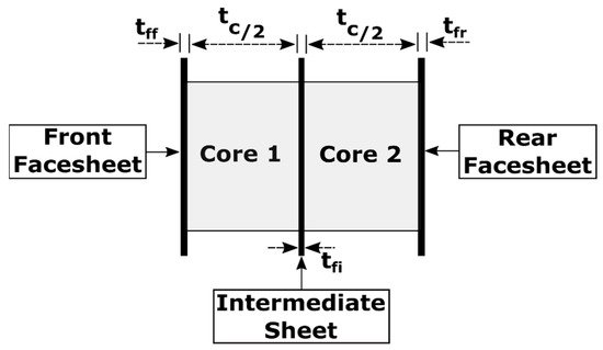
Double honeycomb- and multi-honeycomb-core structures are feasible options to supplement the ballistic performance of structures against HVI. A double-honeycomb (DHC) panel configuration is illustrated in Figure 3.
Turner et al. compared the advantages of DHC to single honeycomb-core (SHC) sandwich panels experimentally, using 15 and 10 ballistic tests, respectively [18]. Experimentation aided in developing BLE, which confirmed a ballistic limit increase of 1 mm to 1.8 mm at 5 km/s due to the use of DHC. Critical diameters increased from 0.583 mm to 0.913 mm at 12 km/s. Additionally, the number of penetrating particles diminished by a factor of 3.7 at the expense of an areal density increase of approximately 40.6% to that of SHC sandwich panels (0.345 g/cm2). By introducing an intermediate facesheet, DHC structures effectively reduced the influence of the debris cloud channeling effect [18][49]. Disruption caused by the intermediate facesheet showed a reduction in fragment size in the cloud and post-impact velocity by approximately 50%, resulting in less damage to the rear facesheet, further improving performance.
Taylor et al. evaluated the shielding performance of SHC and DHC via simulations using AUTODYN-2D and 3D under normal HVI [36]. Comparative simulations were performed at velocities of 7 km/s and 14 km/s with projectile diameters of 0.289 mm and 0.181 mm. Perforation diameter of the SHC rear facesheet was observed to be three cell diameters greater than that of the DHC. Double honeycomb-core structures exhibited more radial expansion and less channelling.
Improvements to DHC were investigated by Liu et al. by varying the transverse position of the intermediate facesheet, opposed to placing the intermediate facesheet at the midspan of the core [38]. It was determined that improved shielding performance occurs when the intermediate facesheet is placed one equivalent shielding distance (the maximum distance fragments travel through thickness prior to striking a cell wall) from the front facesheet. As a result, the number of perforating events lowered in comparison to standard DHC, and damage to the rear facesheet was reduced. To further inhibit debris fragments located in the cloud, a multi-honeycomb-core structure was proposed. With the inclusion of multiple facesheets, increased interaction with the debris cloud was achieved, resulting in improved shielding properties. The multi-honeycomb-core structure consisted of four intermediate facesheets, placed one equivalent shielding distance from another, with a total mass equivalent to that of the intermediate facesheet previously investigated. Liu et al. continued experimentation and simulation on staggered DHC (a DHC configuration where one layer of honeycomb is displaced with respect to another, as exemplified in Figure 4), concluding that debris fragmentation and debris-cloud spread is more prominent, reducing the channeling effect. Accordingly, an increase in core-energy absorption was observed, resulting in a reduction in rear facesheet damage to that of standard DHC and SHC [39].
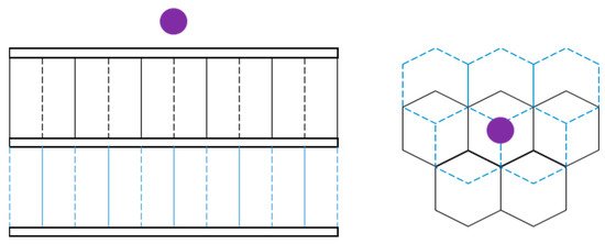
Figure 4. Staggered DHC sandwich panel configuration.
2.1.8. Experimental Database for HVI on HCSP
To better understand gaps in current HCSP experimental testing and visualize data points in the existing test database, a diagram was prepared that identified different impact conditions and sandwich panel design configurations. The diagram contains a depiction of all HVI experiments with HCSP that could be found in the literature.
A single parameter chosen to characterize different HCSP configurations (“a panel configuration index”) on the diagram (vertical axis in Figure 5) was the density of a sandwich panel (derived from thicknesses and densities of facesheets and core), normalized by the density of a “reference HCSP panel”, (ρpanelρref). The latter was represented by a 25.4 mm thick Al-core, possessing a nominal density of 0.05 g/cm3 and 1 mm thick Al facesheets with a density of 2.70 g/cm3.
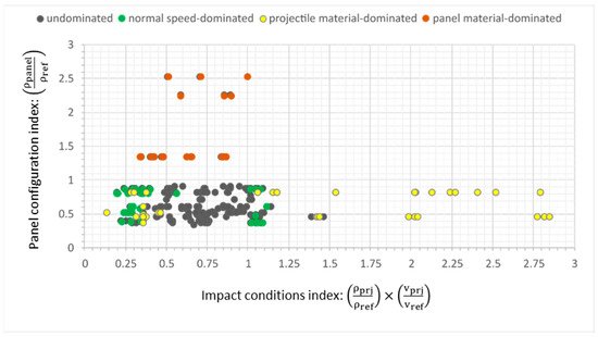
Figure 5. Hypervelocity impacts (HVIs) on honeycomb-core sandwich panels (HCSPs): tested panel configurations versus impact conditions used in experiments.
A parameter chosen to represent different impact conditions (“an impact conditions index”; horizontal axis in Figure 5) was a multiple of two normalized values: density of a projectile used in experimentation, normalized by a reference projectile density (aluminium, 2.70 g/cm3), and normal projectile velocity, normalized by a reference speed (7 km/s), i.e., (ρprjρref)×(vnvref).
Points with green, yellow, and orange centers pertain to data heavily influenced by normal speed, projectile material, and panel material, respectively. The following observations can be made based on the plotted data:
-
The presence of only a few scattered points with yellow markers in the lower right corner of the diagram shows that only a very limited number of tests were made with high-density projectiles. These materials included stainless steel and higher medium-density materials, such as aluminium oxide and titanium, which were tested over a normal velocity range of 1.25–6.23 km/s.
-
Experiments conducted with low-density projectiles are predominantly in the lower left-hand side of Figure 5. The projectiles were composed of Nylon, tested over a normal velocity range of 1.9–6.7 km/s. Again, only a few such experiments were reported in the literature, and the majority of all tests were conducted with medium-density projectiles.
It should be noted that impact scenarios involving high impact angles were also restricted to the lower-left hand corner of the diagram, because the normal velocity component would be smaller with increasing incidence, as detailed by the green left-hand cluster.
Experiments with panel configurations significantly deviating from the reference are highlighted in orange. The highest extremes were composed of all-aluminium panels with increased facesheet thickness.
Trends were observed for points that strayed away from the reference conditions but were not drastically affected by either speed or material. For points below unity, the majority being all-Al samples, facesheet thickness was less than reference 1 mm and cores were of greater-than-reference thickness. Inversely, as facesheet thickness increased and core-thickness decreased to that of the reference panel, data raised above unity, which held even for non-metallic materials (mainly CFRP).
2.2. Predictive Models
Several design and performance BLEs have been described in the literature for sizing HCSP. Design BLEs evaluate the required thicknesses of facesheets for a given particle diameter, whereas performance BLEs evaluate critical projectile diameter for a given set of facesheet thicknesses. Equation (1) represents a design BLE for a Whipple shield (dual wall without core), which serves as the basis for HCSP BLEs, and shows that, to defeat a particle moving with velocity of vp≥7 km/s, a dual-wall system with a front wall (“bumper”) of tb≥0.25⋅Dp⋅ρpρb should have a rear wall with a thickness equal to:
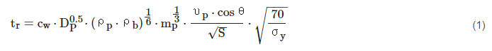
where tr is the rear wall thickness (cm); Dp, mp, and ρp are the projectile diameter (cm), mass (g), and density (g/cm3), respectively; tb and ρb are the thickness (cm) and density of the front wall material (g/cm3); S is the overall spacing between the front and rear wall (cm); cw = 0.16 cm2⋅ sec/g2/3 ⋅ km; σy is the rear wall yield stress (ksi); and ϴ is the impact angle [11].
A fundamental performance Whipple shield BLE, the Christiansen modified Cours-Palais Whipple-shield equation [8], is displayed as Equation (2):
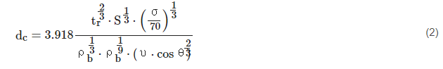
It defines a critical projectile diameter, dc (cm), based on material definitions, projectile speed and impact angle and panel composition (rear wall thickness (cm) and spacing between front and rear wall (S)). Here, υ represents projectile velocity (km/s) and σ is the yield strength of the rear wall (ksi).
According to [11], the ballistic limit for honeycomb-core sandwich panels can be roughly estimated using the Whipple shield Equation (1), where the parameter S, representing the standoff distance in the original Whipple shield equation, is replaced by either the product of twice the honeycomb cell diameter, Dcell (cm), or by the core thickness, whichever is less:
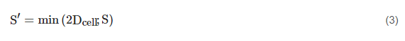
This constraint reflects the fact that honeycomb panels are more easily penetrated as compared to the dual walls, because of channeling of the debris cloud after perforation of the first facesheet. This channeling results from the interaction of the debris cloud with the cells of the honeycomb.
Another design equation, described in [12], estimates the required facesheet thickness, tf, as:
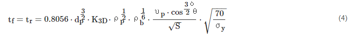
where non-dimensional coefficient K3D = 0.4 for the case of an aluminium outer bumper; and δ = 4/3 if 45° ≥ ϴ ≤ 65° or 5/4 if 45° < ϴ > 65°. For a CFRP outer bumper K3D = 0.4 and δ = 4/3; otherwise K3D = 0.4 and δ = 4/3 if 45° ≥ ϴ ≤ 65° or 5/4 if 45° < ϴ > 65°, identical to the Al outer bumper configuration.
For performance BLEs, a comparison paper investigating BLE for CFRP/AL HCSP structures was documented by Ryan et al. [30]; this paper expanded upon findings by Schaefer et al. [32]. Comparisons were reviewed against results produced by four approaches, referred to as Frost-1, Frost-2, Taylor, and Modified ESA Triple Wall (MET) [25][32][50], where all were fundamentally derived from Equation (2) using equivalent thickness Al facesheets to replace CFRP facesheets and setting honeycomb-core thickness equal to the Whipple-shield bumper spacing parameter [8][32]. The Frost-1 approach substituted in (2) properties and thicknesses of the composite materials without modification [30][32]. The other approaches used different methodologies to determine the equivalent thickness of Al facesheets. In particular, Frost-2 accounted for the density and yield strength of Al and CFRP, while Taylor considered density for the front facesheet and, as noted in [25], an empirically evaluated scaling factor of 0.5 when calculating the equivalent rear facesheet thickness. The Modified ESA Triple Wall equation developed by Schaefer et al. [32] is displayed as Equation (5):
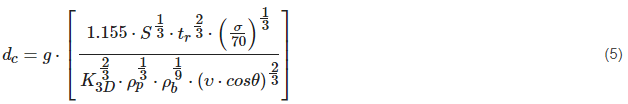
Here, equivalent Al facesheet thickness tr is calculated according to the material’s density as tr = tr,CFRP×ρCFRPρAl. Non-dimensional empirical parameters are given as K3S = 0.7, and K3D = 0.0767 + 0.1833⋅tr, where tr is in millimetres; a dimensionless multiplier g is included to enable definition between different failure types (no detached spallation: g=0.65; no perforation: g = 0.83).
Schaefer et al. compared the effectiveness of the MET approach to the Frost-1, Taylor, and Christiansen approaches, using ENVISAT, Taylor’s and AXAF impact test data as a comparative baseline [32]. It was concluded that Frost-1 and Christiansen’s approaches overpredicted the critical projectile diameter for the ENVISAT and Taylor test sets. In contrast, the Taylor and MET approaches showed promise, exhibiting agreeable predictions for both the Taylor and ENVISAT subsets, as well as with conservative predictions with the AXAF impact data. For CFRP/Al HCSP, with increasing core and facesheet thicknesses, Taylor and MET approaches showed great compatibility, inversely to that displayed by the Frost-1 approach.
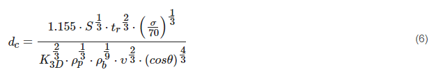
A modification of MET BLE proposed in [30] and referred to as the Schaefer Ryan Lambert (SRL) method is provided in Equation (6), and resulted in good agreement with testing conducted, being comparable to or improving predictive capacity while reducing the number of non-conservative predictions to that of the Frost-1, Frost-2, Taylor and MET approaches [25][30][32][50].
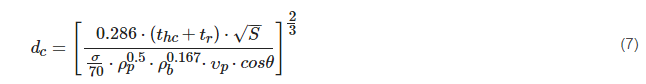
Further modifications can be made to describe impact conditions and design parameters that are influential, but have not been included in Equations (3)–(6). Kang et al. investigated the effects of cell size and cell wall thickness [51]. This investigation focused on their influence with respect to channelling effect, with findings concluded from experimental HVI data and numerical simulations. Evidently, as cell size decreased, the damage observed increased, as did the channelling of the fragments. As cell wall thickness increases, its perforation by projectile fragments becomes more difficult due to the increased resistance exerted by the cell wall, resulting in lower lateral expansion of the debris cloud and more focusing/channelling. Reducing thickness of cell walls also reduced the channelling effect, as determined by Lakais et al. [52]. Investigations by Schubert et al. also concluded that cell wall thickness significantly influences ballistic performance. Schubert et al. noted a lack of honeycomb-core parameters inclusion in BLEs [53]; however, work by Sibeaud et al. has incorporated influences of honeycomb cell dimensions through a parameter thc, the thickness of honeycomb cell walls, which will be perforated by the projectile with incidence θ, in a newly proposed BLE [37]:
Here
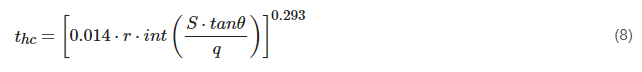
where parameters q and r in Equation (8) characterize the geometry of the honeycomb cell, as shown in Figure 6.
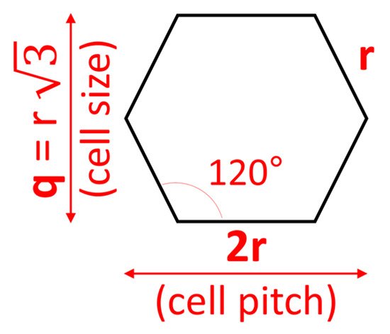
Figure 6. Honeycomb cell parameters in Equation (8).
Importantly, parameter thc in the Sibeaud BLE is a function of the impact obliquity, and will be zero for normal impacts, as follows from Equation (8). Therefore, this BLE does not take into account the effect of honeycomb cell size in case of normal impact.
3. Foam-Core Sandwich Panels
3.1. Experimental Studies
Micro-meteoroids and orbital debris can be combated with alternative shielding applications, such as open cell foam-core sandwich panels (FCSP), which possess comparable or improved ballistic performance to HCSP due to lack of channeling effect and repetitive interaction of the projectile fragments with individual ligaments of an open-cell foam, which was found to result in significantly reducing the fragments’ damaging potential (the so-called “multishock effect” of foam [5][54]) [16][19][21].
Traditional FCSP configurations consist of two facesheets with an internal foam-core. Despite differences in core design, similarities can be drawn from existing research results regarding MLI and facesheet materials and design, which are universal between both FCSP and HCSP. To better understand HVI phenomena of FCSP, parameters specific to open-cell foam-core structures, such as pore density (measured in pores per inch (PPI); Figure 7), foam relative density, and differing configurations: single foam-core (SFC) and double foam-core (DFC) will be discussed, supplemented by results obtained from HVI experiments found in the literature. It should be noted that, unlike HCSP, only few references were available for FCSP structures, including works by Yasensky and Christiansen [21], Ryan and Christiansen [19], and Pasini et al. [55].
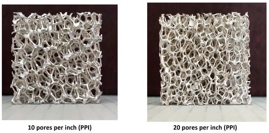
Figure 7. 25.4 mm × 25.4 mm × 12.7 mm samples of 8% open-cell aluminium foams with different pore sizes.
3.1.1. Effect of PPI
The effect of PPI on ballistic performance was investigated via nominally identical impact conditions in [19]. Experimentation targeted 10 PPI, 20 PPI and 40 PPI, 1.0 inch Al-core samples, which were 1-inch-thick. The samples were subjected to 1.2–4.0 mm spherical projectiles with a hypervelocity regime of 6.62–7.05 km/s, and for 0°, 45° and 60° impact angles. Results were comparable amongst the three panel configurations for 2.1 mm and 2.5 mm impactors for 0 and 45° obliquity. Upon approaching each structures’ ballistic limit using 2.0 mm projectiles at normal incidence, perforations observed were attributed to individual fragments progressing well throughout open cavities in the foam-core. It was concluded that ballistic performance increased with PPI due to an increased likelihood of successive impacts between foam ligaments and projectile fragments, significantly improving protective capability and core-projectile collisions; also confirmed in [55].
Similar findings could be concluded from works by Yasensky and Christiansen, where 30 HVI tests were commissioned to evaluate the ballistic performance of metal foam sandwich panel structures, core materials being Al and titanium [21]. The metal foam sandwich structure configurations tested included an array of varying core thicknesses and PPI. Al configurations had 0.5 inch and 2.0 inch thickness for 10 PPI and 40 PPI, respectively, titanium configurations possessed 0.5 inch core thickness for 60 PPI. By approximating the ballistic limit from testing, it was concluded that 40 PPI Al samples, independent of core thickness, displayed better ballistic performance than the 10 PPI counterparts.
3.1.2. Effect of Relative Density
Relative density is the density of a foam divided by the density of the solid parent material of the ligaments. To interpret its effect, Ryan and Christiansen compared 1.0 inch Al 40 PPI samples with 3–5% and 6–8% relative densities, under identical impact conditions for 0° and 60° incidence [19]. Resulting damage induced by 2.0 mm spherical projectiles—at 0° incidence—yielded minimal perforation for both samples, however the core–debris cloud interactions differed drastically. Full core penetration by the debris cloud was noted in the 3–5% relative density sample, although only approximately 80% for the 6–8% sample. Similarly, at 60° incidence (3.4 mm projectiles), damage was more pronounced in the 3–5% sample (cavity volume was larger by a factor of 1.5). Conclusions drawn suggested that increasing the relative density of foams cores leads to improved ballistic capability by suppressing debris cloud propagation. It should be noted, however, that this also results in increased weight of the panel.
3.1.3. Effect of Core Thickness
Effect of metallic foam core thickness was experimentally evaluated by comparing HVI ballistic test results of 0.5 inch, 1.0 inch and 2.0 inch thick Al 40 PPI samples [19]. Testing performed included projectile diameters ranging between 1.3–7.0 mm and impact incidence angles of 0°, 45° and 60°. For normal impacts, it was concluded that the ballistic limits of the 0.5 inch and 2.0 inch samples, measured in terms of kinetic energy required for perforation, were 24% and 618% of the 1.0 inch samples ballistic limit, respectively, which suggests a power dependence of the critical kinetic energy on the foam core thickness. Similar trends were noticed when comparing ballistic limits at incidence. Therefore, as the core thickness increases, as, in turn, does the areal density, ballistic performance improves for both normal and oblique impacts. Secondary confirmation was noted in [21], which compared the effects of Al foam sandwich panels for varying thicknesses of 0.5 inch and 2 inch when subjected to 0° and 45° oblique strikes.
3.1.4. Effect of Facesheet Thickness
Twelve ballistic tests with four different facesheet thickness configurations were reported for impact velocities of 5.88–7.00 km/s, projectile diameters between 2.6–3.6 mm, and for 0° and 45° incidence [19]. Variations in the front facesheet thickness ranged from 0.254–0.508 mm and rear facesheet thickness tested included 0.508 mm and 0.8128 mm. Compared to tests previously conducted, the ballistic performance of the base 1.0 inch aluminium 40 PPI sample was drastically improved for a slight trade-off of additional weight, stemming from heightened facesheet thickness. Modifications to the front facesheet yielded minimal influence in contrast to the performance increase gained by adding thickness to the rear facesheet.
3.1.5. Effect of Sandwich Panel Configuration
Influences of differing core-configurations have been studied experimentally; three configurations were tested over five HVI tests between 6.89–6.97 km/s, 4–4.5 mm spherical projectiles, and for normal incidence [19]. Testing encompassed a 2.0 inch aluminium foam-core sample possessing a 40 PPI core, separated by a Kevlar/Nextel–epoxy intermediate facesheet, and a secondary 5 PPI core. Another configuration considered a reversed orientation, with a 5 PPI core impacted first and equipped with the Kevlar–epoxy intermediate layer. It was determined that intermediate facesheets re-focused the debris cloud, confirmed by the reduction in lateral expansion of the cloud, increasing energy concentration, and the risk of catastrophic failure (rupture of the rear facesheet). Additionally, results for two single aluminium-core configurations composed of 40, 20 and 5 PPIs collectively, arranged in an increasing and decreasing PPI fashion, were reported [19]. No ballistic performance enhancement was achieved when compared to a standard 40 PPI Al-core structure.
3.1.6. Experimental Database for HVI on FCSP
To better understand gaps in current FCSP experimental testing and visualize data points in the existing test database, a diagram was prepared that identified different impact conditions and sandwich panel design configurations. The diagram contains a depiction of all HVI experiments with FCSP that could be found in the literature.
A single parameter chosen to characterize different FCSP configurations (“a panel configuration index”) on the diagram (vertical axis in Figure 8) was the density of a sandwich panel (derived from thicknesses and densities of facesheets and core), normalized by the density of a “reference FCSP panel”, (ρpanelρref). The latter was represented by a 25.4 mm thick Al-core possessing a relative density of 7% (0.189 g/cm3) and 0.254 mm thick Al facesheets with a density of 2.70 g/cm3.
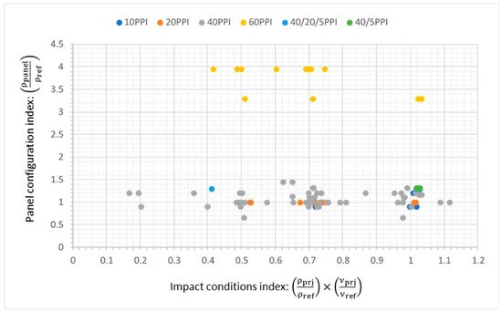
Figure 8. Foam-core structures; panel versus projectile properties.
A parameter chosen to represent different impact conditions (“an impact conditions index”; horizontal axis in Figure 8) was a multiple of two normalized values: density of a projectile used in experimentation, normalized by a reference projectile density (aluminium, 2.70 g/cm3), and normal projectile velocity, normalized by a reference speed (7 km/s), i.e., (ρprjρref)×(vnvref).
It can be deduced from Figure 8 that 40 PPI foam-core panels dominated the experimental investigation results. Of ninety-six experiments sourced, ninety-three were performed with Al projectiles and three with soda–lime glass, both lying within the medium-density classification, and as such influences of projectile density lay near unity. With this stated, variation along the horizontal axis was the result of the normalized normal velocity. As obliquity increased, a lowering of the normal component of velocity occurred, and as such only few highly oblique strikes (Θ ≥ 60°) were noted with the abundance of experimental work being conducted at 0° or 45°. Clustering of data points about unity on the horizontal axis represent experiments conducted with normal strikes, whereas clustering surrounding 0.7 correlates to 45° strikes.
Regarding the influences of panel configuration, a distinction between material types is definite, because all 60 PPI panels were all-titanium (yellow markers in Figure 8), the remainder being all-Al panels. Additionally, with increased core and facesheet density to that of Al, and with comparatively thick facesheet and core sizing, noted titanium samples were positioned high. Effects of decreasing facesheet thickness are evident in the titanium samples with two configurations being defined, possessing either 0.711 mm or 0.864 mm facesheets. Variation in Al samples with respects to panel configuration was attributed to changes in core-thickness. An increase in core-thickness resulted in a decrease from unity, whereas a decrease in core-thickness resulted above unity, and evidently fewer experiments were conducted with core configurations greater than 1 inch.
3.2. Predictive Models
Ryan and Christiansen proposed and validated a BLE defining the perforation threshold for Al open-cell foam core sandwich panels subjected to HVI as:
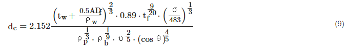
Here, dc is the critical projectile diameter (cm), υ is the projectile impact speed (km/s), and θ is the impact angle. Rear facesheet thickness is represented by tw, and tf is the foam-core thickness (cm). Projectile, rear, and front facesheet densities are given as ρp, ρw and ρb with units of g/cm3. ADf is the foam-core areal density (g/cm2); and the yield stress of the rear facesheet material, σ, is given in MPa. Equation (9) is derived from the Christiansen modified Cours-Palais Whipple-shield Equation (2), and is considered a conservative approach [19][21]. Unlike the HCSP BLE’s based on the Cours-Palais relationship, observations from experimental results noted that FCSP performance scales with increasing velocity in a way similar to that of a spaced multi-wall shield. Comparing predictions of this model against ninety-nine experimental HVI tests, seventy-one were predicted accurately (72%). The validation was performed using Al spherical projectiles and all-Al panels only.
Previously, Ryan, Christiansen and Lear defined a preliminary BLE for metallic foam structures, encompassed in Equation (10), valid for fully fragmented (shattered upon impact) projectiles [54].
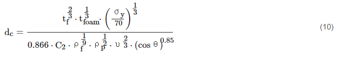
Here, core and facesheet thickness are represented by tfoam and tf, respectively, with units of cm and coefficient C2 = 0.15 · (tfoam)−0.6. Facesheet and projectile densities are ρf and ρp, in g/cm3. Facesheet yield strength is given as σy, in ksi. Experimentally tested foam-core sandwich panels used for fitting the ballistic limit equation were Al foam-cores possessing a relative density of 6–8%. As a result of testing, it was observed that a good agreement was made with 17 HVI tests conducted, with an estimated 82% accuracy.
References
- Pelton, J. Space Debris and Other Threats from Outer Space; Springer: Berlin, Germany, 2013.
- Christiansen, E. Meteoroid/Debris Shielding; NASA TP-2003-210788; NASA: Houston, TX, USA, 2003.
- Protecting the Space Station from Meteoroids and Orbital Debris; National Academies Press: Washington, DC, USA, 1997.
- Christiansen, E.; Kornel Nagy, L.; Dana, M.L.; Thomas, G. Space Station MMOD Shielding. Acta Astronaut. 2009, 65, 921–929.
- Destefanis, R.; Schäfer, F.; Lambert, M.; Moreno, F.; Schneider, E. Enhanced Space Debris Shields for Manned Spacecraft. Int. J. Impact Eng. 2003, 29, 215–226.
- Akahoshi, Y.; Ryuta, N.; Makoto, T. Development of Bumper Shield Using Low Density Materials. Int. J. Impact Eng. 2001, 26, 13–19.
- Whipple, F.L. Meteorites and Space Travel. Astronom. J. 1947, 52, 131.
- Christiansen, E.L. Design and Performance Equations for Advanced Meteoroid and Debris Shields. Int. J. Impact Eng. 1993, 14, 145–156.
- Christiansen, E.; Crews, J.; Williamsen, J.; Robinson, J.; Nolen, A. Enhanced meteoroid and orbital debris shielding. Int. J. Impact Eng. 1995, 17, 217–228.
- Destefanis, R.; Faraud, M.; Trucchi, M. Columbus debris shielding experiments and ballistic limit curves. Int. J. Impact Eng. 1999, 23, 181–192.
- Arnold, J.; Christiansen, E.L.; Davis, A.; Hyde, J.; Lear, D.; Liou, J.C.; Lyons, F.; Prior, T.; Studor, G.; Ratliff, M.; et al. Handbook for Designing MMOD Protection; NASA JSC-64399, Version A, JSC-17763; NASA: Houston, TX, USA, 2009.
- Ryan, S.; Christiansen, E. Micrometeoroid and Orbital Debris (MMOD) Shield Ballistic Limit Analysis Program; NASA/TM–2009–214789; NASA: Houston, TX, USA, 2010.
- Protection Manual; IADC-04-03; Inter-Agency Space Debris Coordination Committee, NASA: Houston, TX, USA, 2011.
- Adams, D.O.; Webb, N.J.; Yarger, C.B.; Hunter, A.; Oborn, K.D. Multi-Functional Sandwich Composites for Spacecraft Applications: An Initial Assessment; NASA/CR-2007-214880; NASA: Houston, TX, USA, 2007.
- Bylander, L.A.; Carlström, O.H.; Christenson, T.S.R.; Olsson, F.G. A Modular Design Concept for Small Satellites. In Smaller Satellites: Bigger Business? Springer: Amsterdam, The Netherlands, 2002; pp. 357–358.
- Cherniaev, A.; Telichev, I. Weight-Efficiency of Conventional Shielding Systems in Protecting Unmanned Spacecraft from Orbital Debris. J. Spacecr. Rocket. 2017, 54, 75–89.
- Krisko, P.H. The New NASA Orbital Debris Engineering Model ORDEM 30. In Proceedings of the AIAA/AAS Astrodynamics Specialist Conference, San Diego, CA, USA, 4–7 August 2014.
- Turner, R.J.; Taylor, E.A.; McDonnell, J.M.; Stokes, H.; Marriott, P.; Wilkinson, J.; Catling, D.J.; Vignjevic, R.; Berthoud, L.; Lambert, M. Cost effective honeycomb and multi-layer insulation debris shields for unmanned spacecraft. Int. J. Impact Eng. 2001, 26, 785–796.
- Ryan, S.; Christiansen, E. Hypervelocity Impact Testing of Aluminum Foam Core Sandwich Panels; NASA/TM–2015–218593; NASA: Houston, TX, USA, 2015.
- Hyde, J.; Christiansen, E.; Lear, D. Shuttle MMOD Impact Database. Procedia Eng. 2015, 103, 246–253.
- Yasensky, J.; Christiansen, E.L. Hypervelocity Impact Evaluation of Metal Foam Core Sandwich Structures; JSC 63945; NASA: Houston, TX, USA, 2007.
- Mespoulet, J.; Héreil, P.L.; Abdulhamid, H.; Deconinck, P.; Puillet, C. Experimental study of hypervelocity impacts on space shields above 8 km/s. Procedia Eng. 2017, 204, 508–515.
- Lambert, M.; Schäfer, F.K.; Geyer, T. Impact damage on sandwich panels and multi-layer insulation. Int. J. Impact Eng. 2001, 26, 369–380.
- Deconinck, P.; Abdulhamid, H.; Héreil, P.L.; Mespoulet, J.; Puillet, C. Experimental and numerical study of submillimeter-sized hypervelocity impacts on honeycomb sandwich structures. Procedia Eng. 2017, 204, 452–459.
- Taylor, E.; Herbert, M.; Vaughan, B.; McDonnell, J. Hypervelocity impact on carbon fibre reinforced plastic/aluminium honeycomb: Comparison with whipple bumper shields. Int. J. Impact Eng. 1999, 23, 883–893.
- Sibeaud, J.M.; Prieur, C.; Puillet, C. Hypervelocity Impact on Honeycomb Target Structures: Experimental Part. In Proceedings of the 4th European Conference on Space Debris, Darmstadt, Germany, 18–20 April 2005; Volume 587, p. 401.
- Taylor, E.; Herbert, M.; Kay, L. Hypervelocity Impact on Carbon Fibre Reinforced Plastic (cfrp)/aluminium Honeycomb at Normal and Oblique Angles. In Proceedings of the Second European Conference on Space Debris, Darmstadt, Germany, 17–19 March 1997; Volume 393, p. 429.
- Taylor, E.; Herbert, M.; Gardner, D.J.; Kay, L.; Thomson, R.; Burchell, M.J. Hypervelocity impact on spacecraft carbon fibre reinforced plastic/aluminium honeycomb. Proc. Inst. Mech. Eng. Part G: J. Aerosp. Eng. 1997, 211, 355–363.
- Ryan, S.; Schaefer, F.; Riedel, W. Numerical simulation of hypervelocity impact on CFRP/Al HC SP spacecraft structures causing penetration and fragment ejection. Int. J. Impact Eng. 2006, 33, 703–712.
- Ryan, S.; Schaefer, F.; Destefanis, R.; Lambert, M. A ballistic limit equation for hypervelocity impacts on composite honeycomb sandwich panel satellite structures. Adv. Space Res. 2008, 41, 1152–1166.
- Schäfer, F.; Destefanis, R.; Ryan, S.; Riedel, W.; Lambert, M. Hypervelocity Impact Testing of CFRP/Al Honeycomb Satellite Structures. In Proceedings of the 4th European Conference on Space Debris, Darmstadt, Germany, 18–20 April 2005; Volume 587, p. 407.
- Schaefer, F.K.; Schneider, E.; Lambert, M. Review of Ballistic Limit Equations for Composite Structure Walls of Satellites. In Environmental Testing for Space Programmes; NASA: Houston, TX, USA, 2004; Volume 558, pp. 431–444.
- Miller, J.E. Observations of Non-Spherical, Graphite-Epoxy Projectiles Impacting a Thermally-Insulated, Double-Wall Shield. In Proceedings of the 15th Hypervelocity Impact Symposium, Destin, FL, USA, 14–19 April 2019.
- Nitta, K.; Higashide, M.; Kitazawa, Y.; Takeba, A.; Katayama, M.; Matsumoto, H. Response of an aluminum honeycomb subjected to hypervelocity impacts. Procedia Eng. 2013, 58, 709–714.
- Lambert, M. Hypervelocity impacts and damage laws. Adv. Space Res. 1997, 19, 369–378.
- Taylor, E.A.; Glanville, J.P.; Clegg, R.A.; Turner, R.G. Hypervelocity Impact on Spacecraft Honeycomb: Hydrocode Simulation And Damage Laws. Int. J. Impact Eng. 2003, 29, 691–702.
- Sibeaud, J.M.; Thamie, L.; Puillet, C. Hypervelocity impact on honeycomb target structures: Experiments and modeling. Int. J. Impact Eng. 2008, 35, 1799–1807.
- Liu, P.; Liu, Y.; Zhang, X. Improved shielding structure with double honeycomb cores for hyper-velocity impact. Mech. Res. Commun. 2015, 69, 34–39.
- Liu, P.; Liu, Y.; Zhang, X. Simulation of hyper-velocity impact on double honeycomb sandwich panel and its staggered improvement with internal-structure model. Int. J. Mech. Mater. Des. 2016, 12, 241–254.
- Giacomuzzo, C.; Pavarin, D.; Francesconi, A.; Lambert, M.; Angrilli, F. SPH evaluation of out-of-plane peak force transmitted during a hypervelocity impact. Int. J. Impact Eng. 2008, 35, 1534–1540.
- Nishida, M.; Hayashi, K.; Toya, K. Influence of impact angle on size distribution of fragments in hypervelocity impacts. Int. J. Impact Eng. 2019, 128, 86–93.
- Chen, H.; Francesconi, A.; Liu, S.; Lan, S. Effect of honeycomb core under hypervelocity impact: Numerical simulation and engineering model. Procedia Eng. 2017, 204, 83–91.
- Miller, J.E. Considerations of Oblique Impacts of Non-spherical, Graphite-epoxy Projectiles. In Proceedings of the 1st International Orbital Debris Conference, Sugarland, TX, USA, 9–12 December 2019.
- Cour-Palais, B.G. The shape effect of non-spherical projectiles in hypervelocity impacts. Int. J. Impact Eng. 2001, 26, 129–143.
- Christiansen, E.; Crews, J.; Kerr, J.; Cour-Palais, B.; Cykowski, E. Testing the validity of cadmium scaling. Int. J. Impact Eng. 1995, 17, 205–215.
- Mullin, S.A.; Littlefield, D.L.; Anderson, C.E., Jr.; Tsai, N.T. Velocity Scaling of Impacts Into Spacecraft Targets at 8 to 15 km/s. In Proceedings of the Hypervelocity Impact Symposium, Austin, TX, USA, 17–20 November 1992.
- Schmidt, R.M.; Housen, K.R.; Piekutowski, A.J.; Poormon, K.L. Cadmium simulation of orbital-debris shield performance to scaled velocities of 18 km/s. J. Spacecraft Rockets 1994, 31, 866–877.
- Schonberg, W.; Williamsen, J. RCS-based ballistic limit curves for non-spherical projectiles impacting dual-wall spacecraft systems. Int. J. Impact Eng. 2006, 33, 763–770.
- Protection Manual; IADC-WD-00-03; Inter Agency Space Debris Coordination Committee, NASA: Houston, TX, USA, 2004.
- Frost, C.; Rodriguez, P. AXAF Hypervelocity Impact Test Results. In Proceedings of the Second European Conference on Space Debris, Darmstadt, Germany, 17–19 March 1997; Volume 393, p. 423.
- Kang, P.; Youn, S.K.; Lim, J.H. Modification of the critical projectile diameter of honeycomb sandwich panel considering the channeling effect in hypervelocity impact. Aerospace Sci. Technol. 2013, 29, 413–425.
- Iliescu, L.E.; Lakis, A.A.; Oulmane, A. Sattelites/Spacecraft Materials and Hypervelocity Impact (HVI) Testing: Numerical Simulations. J. Eng. 2017, 4, 24–64.
- Schubert, M.; Perfetto, S.; Dafnis, A.; Mayer, D.; Atzrodt, H.; Schroder, K.U. Multifunctional Load Carrying Lightweight Structures for Space Design; Institute of Structural Mechanics and Lightweight Design; RWTH Aachen University; Fraunhofer Institute for Structural Durability and System Reliability LBF: Darmstadt, Germany, 2017; pp. 1–11.
- Ryan, S.J.; Christiansen, E.L.; Lear, D.M. Development of the Next Generation of Meteoroid and Orbital Debris Shields. In AIP Conference Proceedings; American Institute of Physics: College Park, MD, USA, 2009; Volume 1195, pp. 1417–1420.
- Pasini, D.L.S.; Price, M.C.; Burchell, M.J.; Cole, M.J. Spacecraft Shielding: An Experimental Comparison Between Open Cell Aluminium Foam Core Sandwich Panel Structures and Whipple Shielding. In Proceedings of the European Planetary Science Congress, London, UK, 8–13 September 2013.


