Your browser does not fully support modern features. Please upgrade for a smoother experience.
Subjects:
Engineering, Ocean
Introduction
Subglacial sediments in aquatic environments are found at the seabed beneath ice shelves, subglacial lake beds, and at the base of ice streams. They contain important paleoenvironmental and paleoclimatic records [1,2] that provide information linking the overlying ice with the aquatic system [3], as well as information on the biodiversity and the evolutionary processes of living organisms under subglacial conditions [4,5] and the subglacial sedimentation processes [6]. Moreover, subglacial sediment cores may even contain more information beyond the age of the ice core [7]. To obtain scientific information and verify hypotheses, in situ exploration and sampling of subglacial sediments [8,9], i.e., subglacial sediment coring, is needed.
Where Subglacial Sediments Occur and Detection Methods
Antarctic subglacial aquatic sediments occur mainly in three environments, as follows: Sub-ice shelves, sub-ice streams, and subglacial lakes [10,11,12]. Figure 1 shows the scheme of subglacial sediment occurrences in Antarctica. However, the sediment depositional processes are still unknown unless sediment cores are collected and sedimentary sequences are analyzed [1,13].
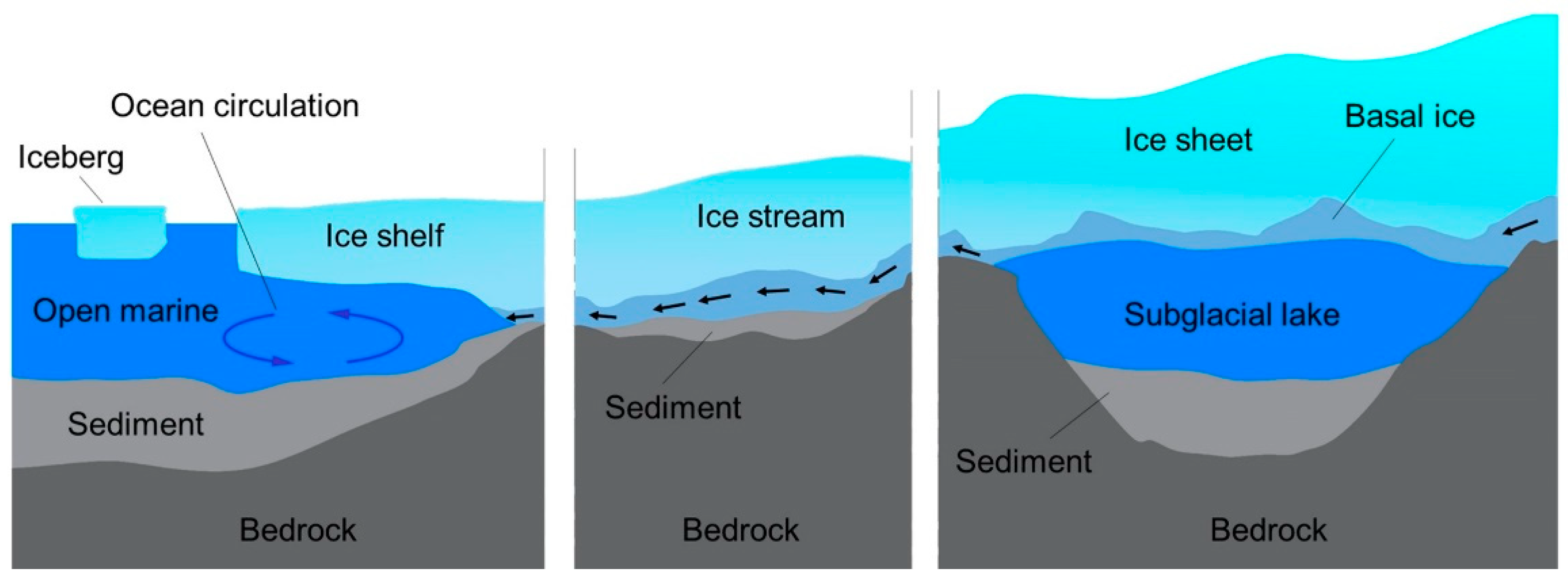
Figure 1. Schematic diagram of exist circumstances of the Antarctic subglacial aquatic sediments.
The sediments beneath Antarctic sub-ice aquatic environments are located and characterized mainly by seismic sounding survey methods that can also provide information on the water cavity thickness [6,8,9]. Along with determining sub-ice bathymetry, seismic reflection data can show the occurrence of soft sediments and even indicate sediment depth and its degree of coarseness or fineness [6]. All of the above information is critical for sediment coring equipment selection, development, and applications [6].
Reasons for the Interest in Coring and Requirements
Compared with lake and ocean sediments, subglacial aquatic sediment deposits are from different and more diverse source materials, from the transport and melting of the overlying ice, the hydrological flow [12], and biological and volcanic activities, for example.
Sediments beneath ice shelves are most likely deposited from two main sources, as follows: The open marine environment and basal debris from the ice shelf base near the grounding zone [10]. Therefore, research on the sub-ice-shelf sediment cores is mainly focused on interpreting presence or absence of the ice shelf in the geological record, inferring the interaction between the sub-shelf and open-water marine environments [3], and obtaining boundary information about sub-ice shelf sedimentation [14,15]. Sub-ice shelf sediment research also aims to study the microbial ecosystem and carbon cycling in these unique environments [15].
Considerable interest in sub-ice-stream sediments focuses mainly on rheology and its importance to ice streaming and the mass balance and stability of the modern Antarctic ice sheet [16]. One of the main aims in obtaining such information is to determine when the ice sheet last decayed, which is critical to assessing the present-day risk of ice sheet collapse and consequent sea-level rise [8,17]. Such information cannot be provided by ice cores, as these are restricted to the age of the ice itself (~1 million years) [7], whereas the sedimentary records show that the last time central West Antarctica was ice-free ~1 million years ago [18]. Sediment cores can provide paleontological and geochemical data for paleo-climate research and infer the time the west Antarctic ice shelves collapsed [19,20].
Over 400 subglacial lakes exist underneath the Antarctic Ice Sheet [21], where the temperature of ice reaches the pressure melting point. Subglacial lake sediment research efforts are more focused on biological questions [9,22,23] and efforts are focused on the following: (i) What form of microbial life exists in Antarctic subglacial lakes [1,9,22,23]; (ii) the post-Pliocene history of the Antarctic ice sheet [1,9]; (iii) paleoenvironmental and paleoclimatic records that can determine the ice sheet dynamics [1,9]; and (iv) the biodiversity and the evolutionary processes of living organisms under unknown habitat conditions [4,9].
Based on these sediment research interests and the requirement for subsequent core analysis, there are two basic requirements for subglacial sediment sampling, as follows: (i) The water–sediment interface should be undisturbed for biological analysis [9,23] and (ii) there should be minimal disturbance and deformation of the layer deposition structure in sediment samples for research based on time scales [9,10], for example, sequence stratigraphic analysis [13].
Sediment Sampling Restrictions and Difficulties in Subglacial Aquatic Environments
Specific Working Conditions
Before sediment coring, an access borehole should be drilled using the hot water drilling method. The diameter of the borehole may range from 10 to ~60 cm [24] and the depth from a few to thousands of meters [4,22]. When the hot-water drill penetrates the ice base, the borehole water level will adjust to the local hydrological level, achieving pressure equilibrium [3]. The sediment coring tools are then deployed, first through the air filled and then water filled parts of the borehole, through the ocean or lake water column if present, to reach the sediment, which is sampled and retrieved to the surface as sediment core samples [8].
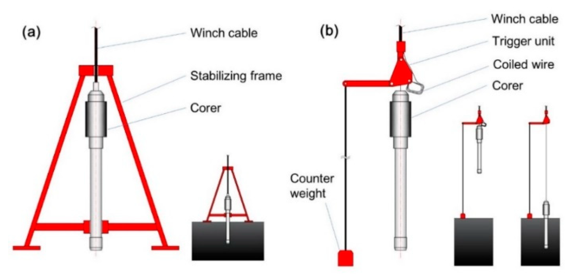
The access borehole closes at rates of between 3 to ~6 mm/h [25,26], i.e., it refreezes at an L113 change to a rate that depends on the ice temperature surrounding the borehole, the water pressure, the initial borehole size, and the water composition [24]. Sub-ice instruments can only be deployed and retrieved during the window of opportunity between the time the borehole is drilled/reamed and the time it refreezes to a certain size [24]. Otherwise, instruments can become stuck in the borehole. Therefore, sediment sampling devices are always cylindrical shaped and primarily designed and selected based on the hot water borehole diameter and water pressure [27]. The stabilizing frame [28] and overhanging trigger system [29] used in lake and ocean sediment coring are not applicable due to their size (Figure 2).
Figure 2. Structure and function schemes of the conventional corers with (a) a stabilizing frame and (b) an overhanging trigger system; the radial sizes (150–600 cm) of these corers are far larger in diameter than can enable access to hot-water drilled boreholes (10–60 cm).
Surface Operation and Control Facilities
The ANDRILL (Antarctic Geological Drilling) project on Ross Ice Shelf [32] used a basic winch and tower, a high-strength cable (with or without power transmission capacity), a control unit, and a platform for sub-ice sediment coring. The cable, winch, and tower were designed to manage loads from between 1500 and 4500 kg [33]. The operational height between the tower top pulley to the borehole surface is generally between 3–6 m, while heights of more than 10 m can be achieved using a hydraulic powered crane [34]. Assembly and disassembly operations of the sampling devices are usually executed by manual rather than by automatic auxiliary equipment.
Complicated Sediment Structure
Subglacial sediments are more heterogeneous compared to normal aquatic sediments, due to the multiple sources of their deposits throughout their histories [12]. The basic composition of such sediments is generally the same as marine sediments (silt, clay, sand fractions, gravels, for example.) but the structure and mechanical properties are strongly influenced by the overlying ice layer dynamics [10]. In some drilling sites, the shear strength of cores obtained can be more than 70 kPa at a depth of 2 m [35], and the surface biological debris (2–4 mm) and deeper interbedded gravel (4–64 mm) become the main factors preventing corers from going deeper [6]. Therefore, coring tools equipped with additional kinetic energy units have been developed to penetrate deeper [11,23].
Although many attempts have been made to collect subglacial sediment samples, only a few studies have successfully recovered sediment samples from beneath Antarctic subglacial settings. Coring results have generally shown low success rates and penetration performance. In this paper, we review the design and characteristic structure of representative sediment coring tools developed for Antarctic subglacial aquatic environments. We provide some constructive suggestions and our expectations regarding the technologies are also included in order to express new ideas on how to improve current coring techniques and corer designs.
Current Subglacial Aquatic Sediment Corers: Method, Working Principle, Design, and Applications
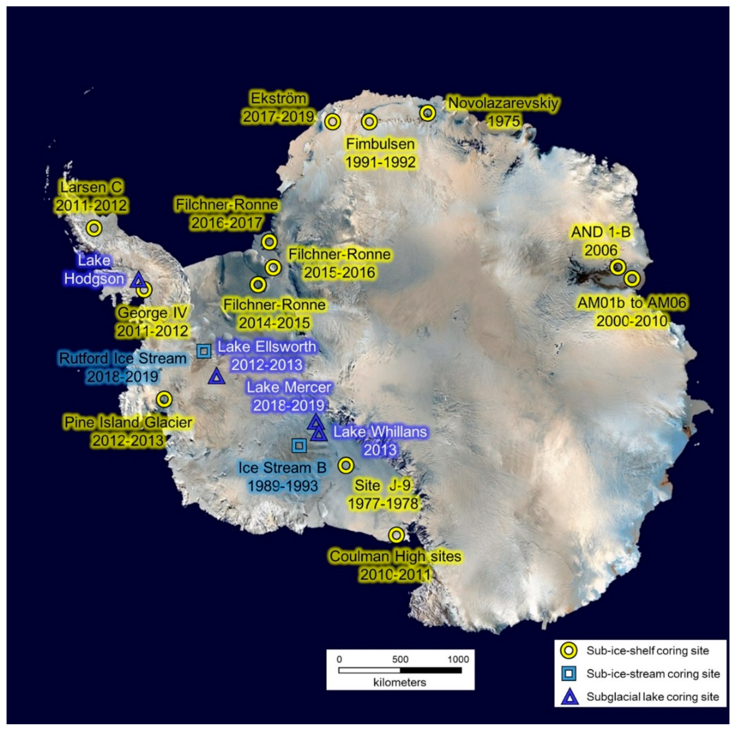
Only a handful of studies have successfully recovered sediment samples from Antarctic subglacial aquatic environments [8]. The coring tools used have been commercial products (e.g., UWITEC corer) or purposely designed based on the requirements of hot water drilling boreholes and the parameters of subsidiary facilities (e.g., gravity corer developed by the Alfred Wegener Institute). For specially designed corers, the coring methods and parameters have been chosen based mainly on the following points: (1) The sampling length aims, (2) sediment properties and thickness that can be roughly derived from seismic reflection surveys [6], and (3) compatibility between coring methods and sediment types [8,33] (e.g., coring requirements for ocean and lake sediments). All corers may be classified into two categories based on their research purpose. The water–sediment interface sampling corer (0.3–2 m core barrel) is used for microbial or organic matter research and the long-tube corer (1.5–6 m core barrel) is used to recover the longest possible time-scale sediment sequence [8,35,36]. Moreover, corers may also be classified based on their working principle, including single gravity percussion corers, hammer percussion corers, vibration liquefaction corers, and piston corers. Here, we review the coring tools that have been custom-designed for, or that have already been deployed in Antarctic subglacial sediment sampling. They are classified based on their working principle and presented according to structural complexity. Drilling sites (Figure 3), locations, and borehole conditions are also presented.
Figure 3. Site locations of subglacial sediment coring in Antarctic.
Gravity and Gravity Piston Corers
Gravity coring is the most widely used method to obtain sediment cores from subglacial aquatic environments [8]. Almost all hot water drilling projects are equipped with a gravity corer if the coring plan involves subglacial sediment coring. The reasons for this are as follows: (1) This corer is associated with higher success rates on most types of sediments (from soft sediments to hard clay) compared to other corers; (2) its simple structure simplifies designs and lowers costs, and (3) its adjustable dead weight makes this corer adaptive to different winch systems and cables [8,37].
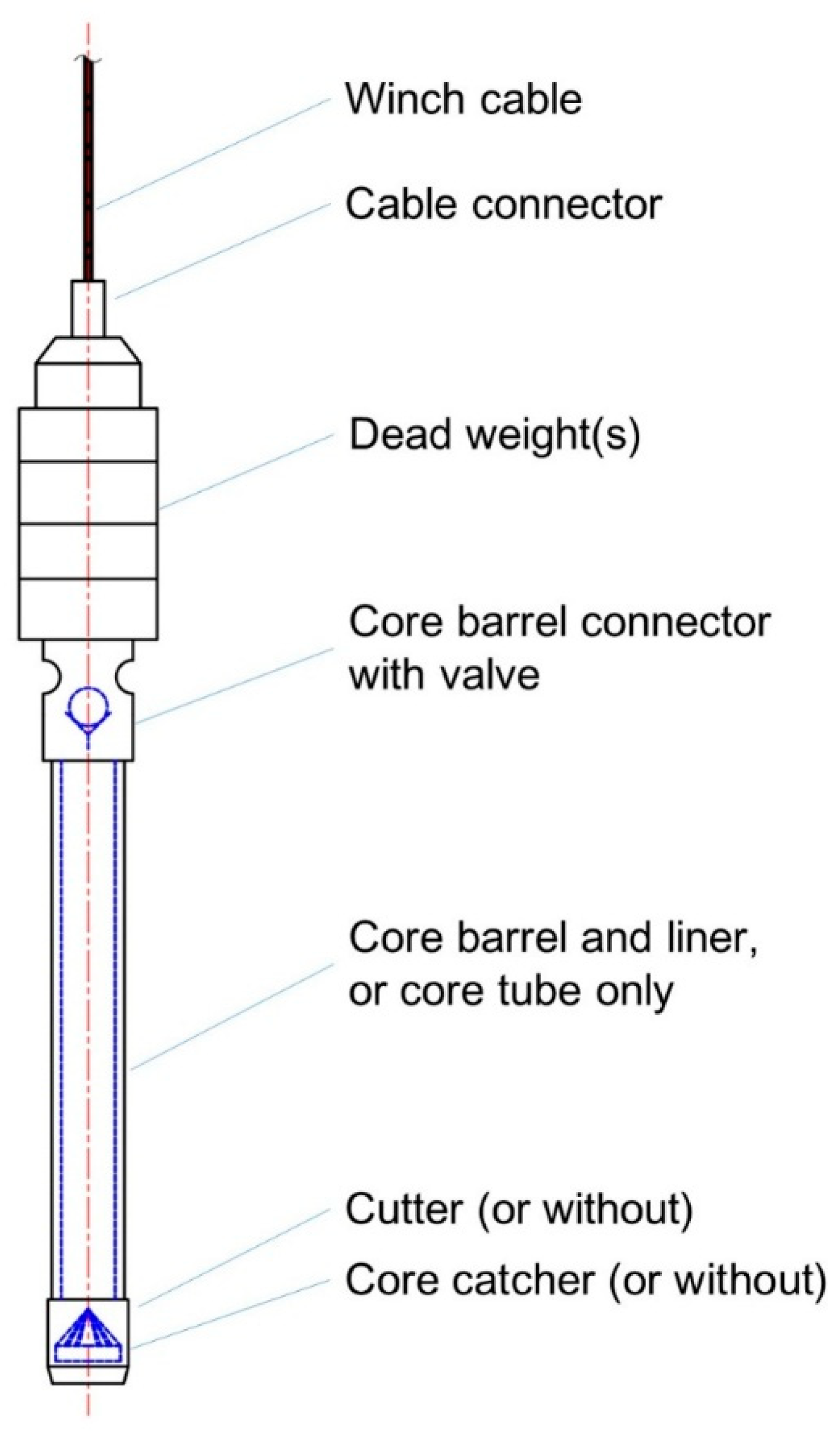
The working principle of the subglacial gravity corer is generally the same as the conventional gravity corer except for the balance beam trigger system [29], which consists of a dead weight, the core tube (double or single tube), an optional cutter, an optional core catcher, a check valve mechanism, an optional tube piston mechanism, and a cable connector (Figure 4). Due to the borehole size restriction, the radial the trigger system must be removed (Figure 2b). As a result, the balance beam rod trigger system cannot be used, thus a surface winch releases the corer at a distance 5–22 m above the sediment surface [35]. Thus, the corer ‘free-falls’ and pushes the core barrel to penetrate through the sediments by its gravitational potential energy [37]. The penetration depth of a gravity corer depends on the net weight of the coring assembly, the diameter of the core catcher and core liner, the hydrodynamic properties of the coring assembly (e.g., water drag resistance), and the physical properties of the sediment [38].
Figure 4. General layout of subglacial sediment gravity corer.
Published data shows that there are mainly two gravity corer types depending on sampling aims, including (1) long tube sequence gravity corers, which will obtain sediment cores 1–6 m long, and (2) light corers, which will obtain undisturbed surface water–sediment interface core samples.
‘Benthos Model 2171′ Gravity Corer
With the possible exception of the sediment corer used on the Novolazarevskiy ice shelf [39] (which was not identified), the first subglacial sediment gravity corer is the ‘Benthos model 2171′ used at Site J-9 (82° 22′ S, 168° 38′ W) as a part of the Ross Ice Shelf Project [40]. During the austral summer of 1977, 58 short cores with lengths of up to 122 cm were collected at Site J-9 [40,41]. Samples were 400 km from the open water of the Ross Sea, where the ice thickness was about 420 m, the marine water column was 237 m, and the distance between the water surface to the seafloor was 597 m [40]. The access borehole was drilled through the ice shelf using a flame-jet drill developed by the Browning Engineering Corporation and produced a hole 30–80 cm in diameter [42]. This corer was also used to obtain 30–60 cm cores from beneath the Fimbulsen Ice Shelf in 1991–1992 [8,43]. The ‘Benthos model 2171′ gravity corer can be equipped with a 2.4 m long liner (ID 67 mm), has a total weight of 110 kg, and can be equipped with a 3 m core barrel [8,40].
‘Wintle’ Corer
The ‘Wintle’ gravity corer was purposely built for sub-ice-shelf sediment sampling. It is 150 cm in length and its maximum diameter is 12 cm [6,44]. This corer was first used at site AM02 (69°42.8′ S, 72°38.4′ E) on the Amery Ice Shelf, where it collected a 144 cm core ~80 km south of the floating ice shelf front in the 2000–2001 drilling season, as part of the Australian National Antarctic Research Expeditions (ANARE) Amery Ice Shelf Oceanographic Research (AMISOR) program [6]. This 144-cm core was X-ray radiographed to examine for any sedimentary structures and ice-rafted debris (IRD) granules (2–4 mm) and pebbles (4–64 mm) were counted for every 5 cm interval downcore [44]. In the 2003–2004 season, a second 47 cm core was collected from site AM01b (69°25.86′ S, 72°26.77′ E), which is 50 km west of the AM02 site. Four other cores between 60 and 124 cm long were obtained from sites AM03 to AM06 in the 2005–2006 and 2009–2010 seasons [10].
AWI Gravity Corer
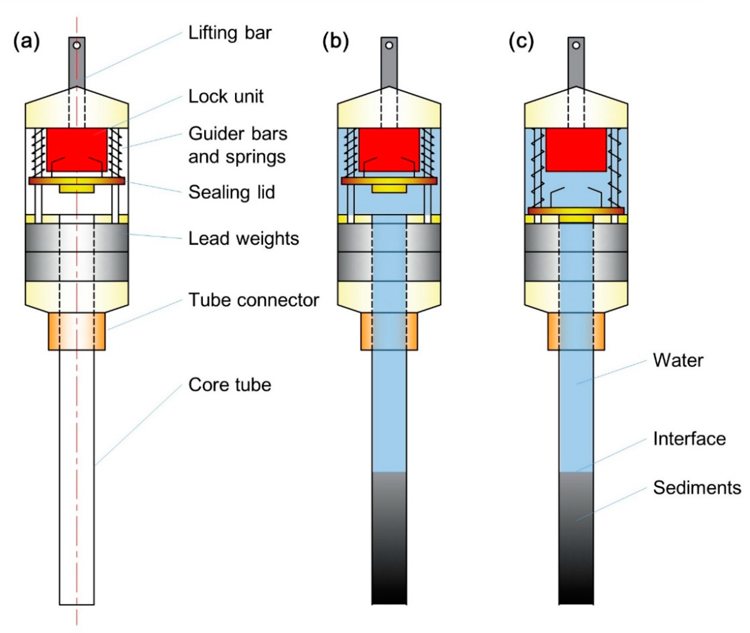
On 16 October 2006, the ANDRILL team used a gravity corer at the AND-1B site (77°53′22″ S, 167°5′22″ E), after drilling the hot water borehole (~40 cm in diameter) and prior to the deployment of the sea riser [35]. This project aimed to recover the water–sediment interface and a few decimeters of sediment below the surface. Eight coring attempts were made and 7 cores with lengths of up to 53 cm were recovered [35]. The small (~80 kg, maximum diameter 22 cm) gravity corer (Figure 5a) was designed and built by AWI (Alfred Wegener Institute). The corer was fitted with a plastic core barrel that was a UWITEC standard plastic liner that was 1.0 or 1.5 m long and 59.5/63 mm in ID/OD and was without a cutter and core catcher [37]. The weight of the corer can be adjusted by adding or reducing lead weight loops. A self-contained tension triggering valve mechanism (lock unit) was installed at the top of the corer. The valve is kept open during the lowering and penetrating steps; it then closes once enough instantaneous tension is exerted on the lifting bar (Figure 5b,c). After passing the corer through the access borehole, it is lowered to 5–25 m above the sea-floor and stabilized for about 1–2 min. Then the surface winch is switched to a ‘free-wheel’ mode and the corer penetrates into the sediment by its gravitational potential energy. After penetration, the surface operator exerts a sudden force to the cable to close the sealing lid. The core with the intact water–sediment interface is kept under vacuum in a space formed by the sealing lid, the core tube, and sediment [35].
Figure 5. (a) Principle structure of the AWI gravity corer, (b) the corer working states during penetrating, and (c) the corer working state of lifting with core.
The AWI gravity corer was again deployed by the ANDRILL team at Coulman High beneath the Ross Ice Shelf between November 2010 and January 2011, as part of preparations for a planned drilling project targeting an Early Cenozoic sequence [37]. In total, 28 cores with lengths of up to 129 cm were obtained from four hot water drilling sites [37].
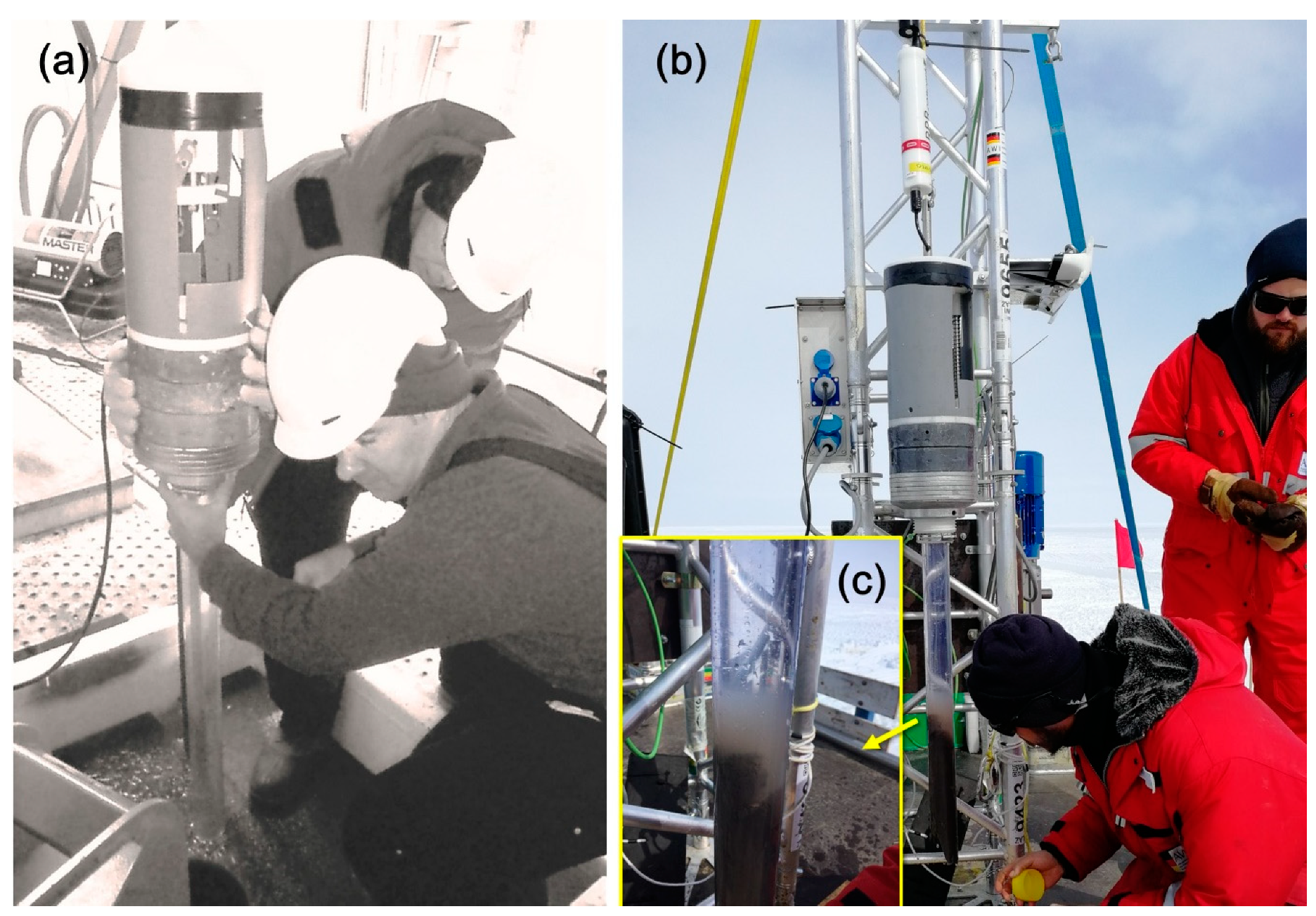
The AWI gravity corer was used in several hot water boreholes (~40 cm) at the Ekström Ice Shelf between November 2018 and January 2019, as part of the Sub-EIS-Obs project [45]. Seven gravity coring attempts were made but only one succeeded in obtaining a water–sediment interface sample with a 46 cm core (Figure 6b) from the drill site, where the ice thickness was 332 m and the seafloor was located ~700 m from the ice surface.
Figure 6. The AWI gravity corer applied at (a) site AND-1b [35] (Reproduced with permission from Terra Antartica Publication, 2007), at (b) the Ekström ice shelf with (c) undisturbed water–sediment interface ((b,c) photographs were taken by Y. Li).
UWITEC Gravity Corer and NIU/UWITEC Multi-Corer
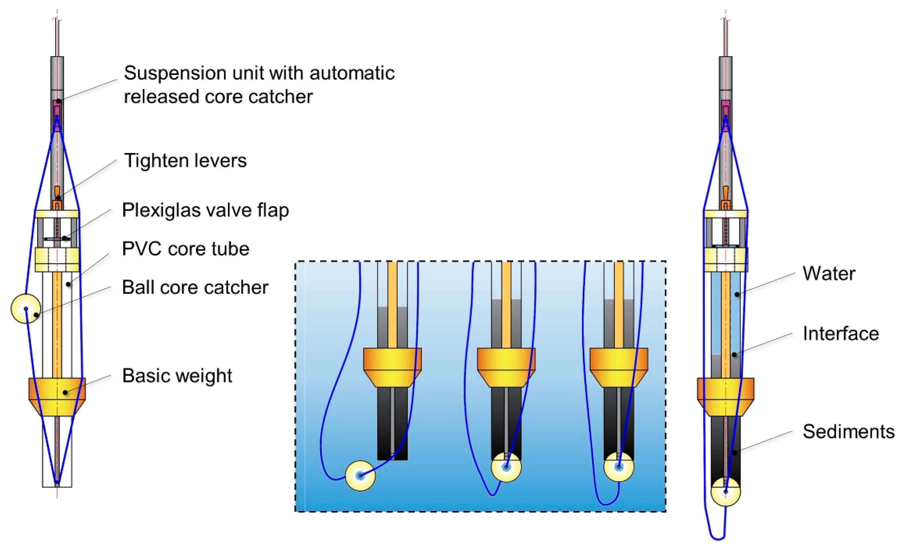
The UWITEC (an Austrian engineering company) gravity corer is designed to sample soft and watery surface sediments with the aim of preserving the water–sediment interface [46]. This gravity corer has a streamlined shape and is equipped with an automatic core catcher (Figure 7). It weighs 5–8 kg and has a maximum OD of no more than 150 mm (without the ball core catcher). The core tube dimensions are standard, with a UWITEC liner with ID/OD measurements of 59.5/63 mm and a length of 80–120 cm. The corer can be released to ‘free-fall’ several meters above the sediment surface. The line-ball core catcher and valve flap automatically seal the tube’s lower and upper ends, respectively, when coring is completed. Additional dead weights can be added if needed, with each tube circular ring weighing 4 kg [46]. The UWITEC gravity corer has successfully retrieved a surface sediment core from a coring site (72°00.259′ S, 68°29.022′ W) at Lake Hodgson [47], where the ice thickness is 3.7 m and the distance between the ice surface and the sediment is 93.4 m [22].
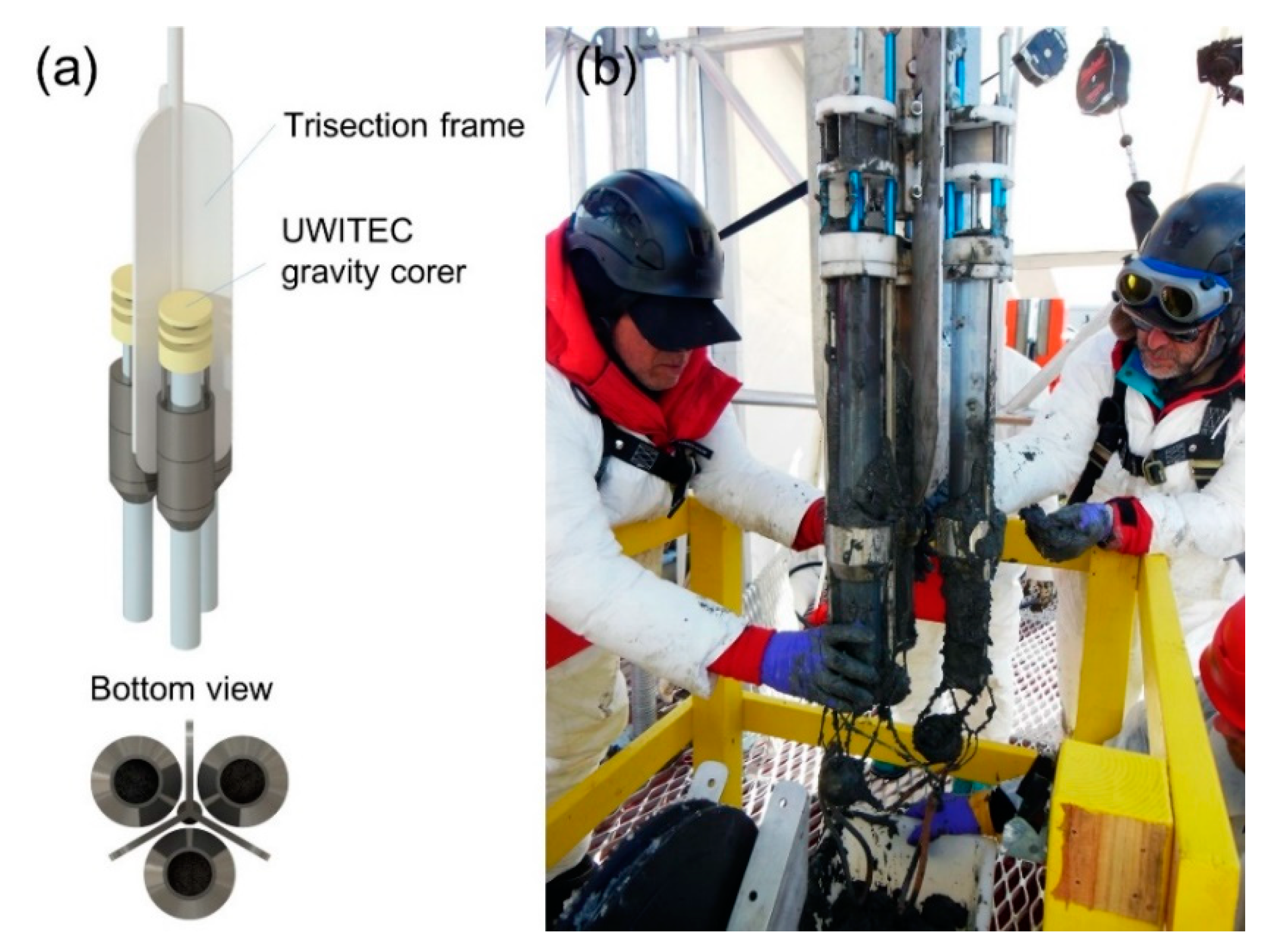
After being modified by Northern Illinois University (NIU), the corer was renamed the NIU/UWITEC gravity multi-corer (Figure 8) [1]. This multi-corer is a combination of three standard UWITEC gravity corers, installed on a trisection frame (Figure 8a). Its working principle is the same as the standard UWITEC gravity corer, but it can take three replicate cores simultaneously after being self-triggered upon striking the bottom sediment. This corer has been used in at least two sites since it was designed, including at the Subglacial Lake Whillans (~60 cm diameter access borehole) site by the WISSARD (Whillans Ice Stream Subglacial Access Research Drilling) team in January 2015 (Figure 8b), where it collected eight good cores with lengths between 20 and 40 cm [48,49]. However, seven attempts were unsuccessful (e.g., corer was stuck in the borehole) because the corer assembly is relatively large, is not streamlined, and is quite light [1,50]. Recently, the corer was deployed at Subglacial Lake Mercer Whillans (~60 cm diameter access borehole) by the SALSA (Subglacial Antarctic Lakes Scientific Access) team in the 2018–2019 season, and at least six water–sediment interface cores were obtained [51].
Figure 8. NIU/UWITEC multi-gravity-corer: (a) 3D structure scheme and multi-core obtained from (b) Subglacial Lake Whillans [50] (photograph was taken by M. Beitch, courtesy of the National Science Foundation).
BAS/UWITEC Gravity Corer
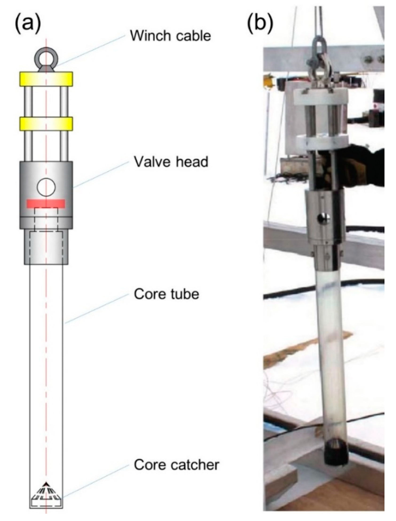
This short corer (Figure 9) was developed cooperatively by BAS (British Antarctic Survey) and UWITEC, with the aim of collecting surface sediment cores in sub-ice-shelf settings. It consists of a valve head, which also functions as a dead weight, a single liner, and an orange-peel shaped core catcher. This corer was used during 2014–2015 and 2015–2016 field seasons by BAS to sample sub-ice-shelf sediments. Approximately 30 cm diameter access boreholes were drilled by a hot water drilling system through the Filchner-Ronne Ice Shelf, where ice thickness ranges between 750–891 m. In total, seven cores were obtained with a combined total length of 265 cm in the 2014–2015 season and at least three cores of up to 55 cm were obtained in the 2015–2016 field season [52]. Three cores with lengths up to 75.5 cm were obtained from BAS drill sites on the Filchner-Ronne Ice Shelf during the 2016–2017 field season, where ice thickness ranges between 597–615 m and water column thickness ranges between 440–643 m.
Figure 9. The BAS/UWITEC gravity corer: (a) General structure and (b) used in the field [8] (Reproduced with permission from Royal Society, 2016).
2.1.6. SLE Gravity Corer
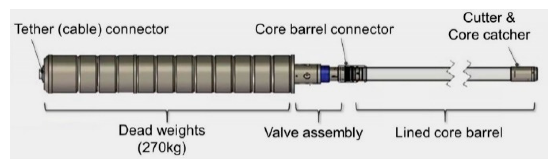
To obtain long sediment core samples through a tether without an electric power supply, the SLE (Subglacial Lake Ellsworth) team proposed a heavy gravity corer (Figure 10) with a 270 kg head weight, enabled for preparative sterilization and cleaning [31]. This corer is equipped with a single tube core barrel that is 3.7 m long and has a 60 mm inner diameter to achieve a reasonable balance between corer diameter and corer weight. The combination of a long and heavy tube with a heavy load was designed for deeper penetration. The entire corer is driven into the sediment by only gravitational potential energy [8].
Figure 10. Schematic of SLE gravity corer [8] (Reproduced with permission from Royal Society, 2016).
This corer was planned to be used in the subglacial Lake Ellsworth in the 2012–2013 season by passing through an access borehole approximately 36 cm wide and ~3000 m deep [36] to obtain old sediments. The seismic reflection data analysis showed that the lake’s sediment is highly porous with a low density, very similar to material found in the deep ocean floor. The sedimentary sequence thickness was estimated to be at least 2 m [53]. Unfortunately, the hot-water drilling failed to access the lake [54] and the SLE gravity corer has not been applied.
WHOI Gravity Corer
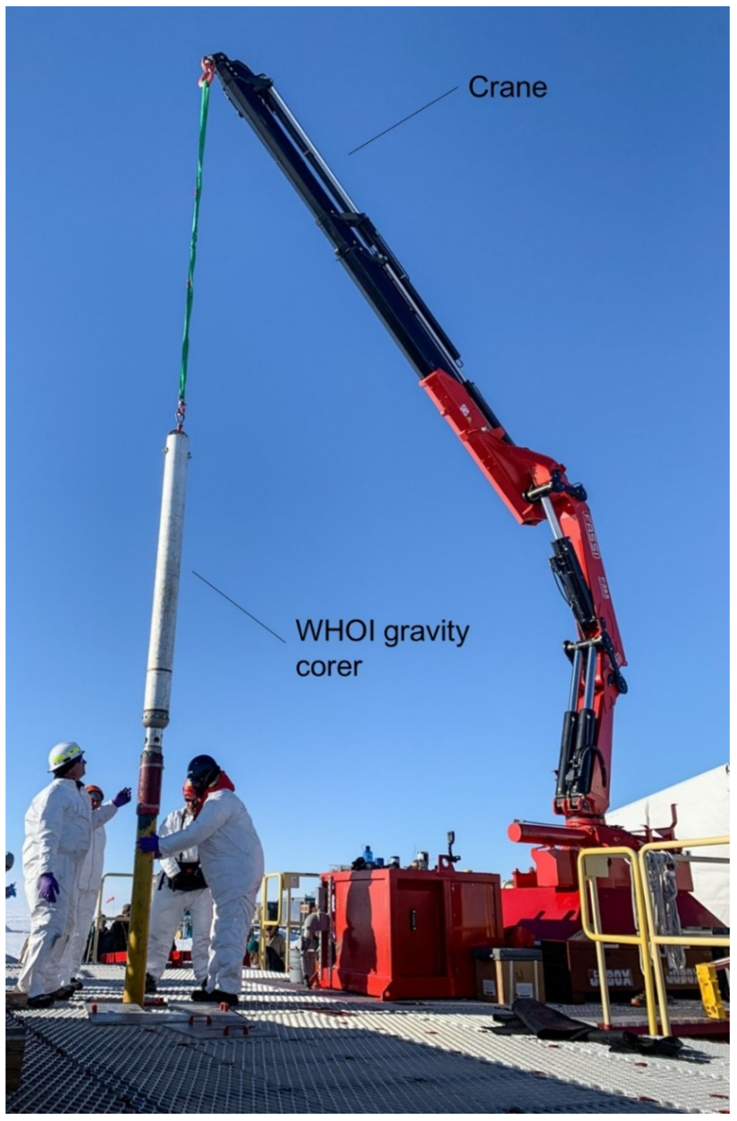
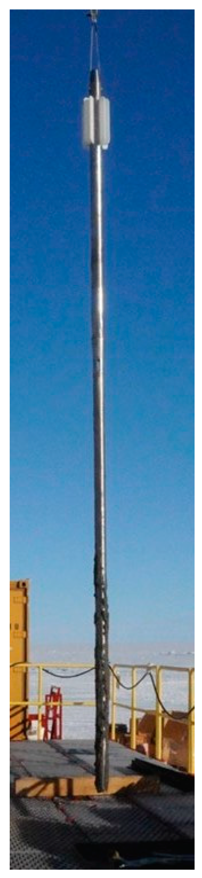
The WHOI (Woods Hole Research Institute) gravity corer (Figure 11) is the largest tool in SALSA’s lineup, with a total length of 9.1 m. Its purpose is to take up to ~6.0 m core samples by its heavy weight (~1130 kg). At subglacial Lake Mercer in 2018–2019 season, the WHOI corer was deployed through a ~60 cm diameter access borehole and it made contact with the sediment bed at a depth of 1084 m. Two cores with lengths of 70 cm and 170 cm were obtained with this corer, setting a new length record in subglacial lake sediment coring [55,56].
Figure 11. The WHOI gravity corer [34] (photograph was taken by K. Kasic, SALSA Education & Outreach).
Hammer/Percussion Corers
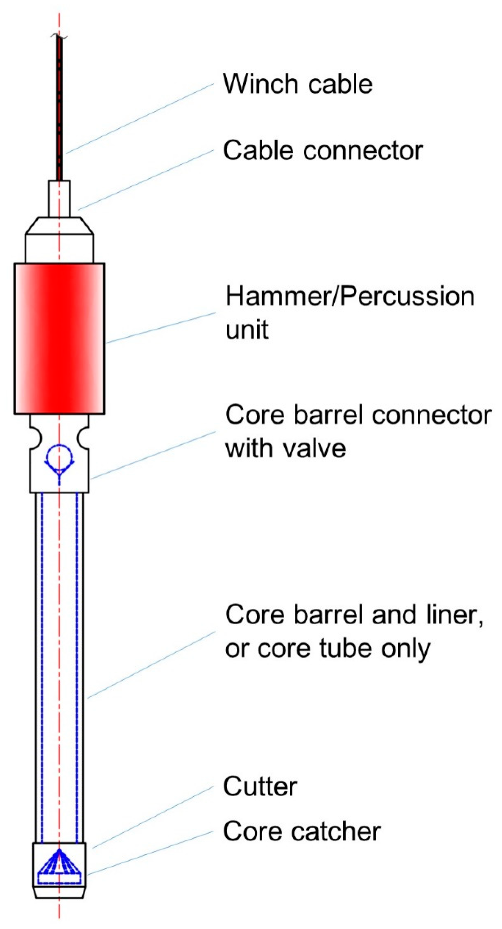
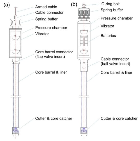
Subglacial aquatic sediment hammer corers or percussion corers (Figure 12) were developed to achieve deeper penetration than the gravity coring tools. The main difference between the hammer/percussion corer and the gravity corer is the power supply used to achieve core tube penetration. Gravity corers penetrate into sediments through single-use, gravity-based energy (dependent on dead weight and release distance); in contrast, hammer/percussion corers are equipped with a hammer/percussion head that provides continuous impact energies to push the cutter and barrel into sediment. The hammer/percussion corer design consists of a double-tube core barrel structure, including a steel core barrel to sustain impact force and the liner to retain the sediment core samples. The hammer/percussion heads are driven by an ice surface cable manually operated, using electric power transferred through an armed cable or batteries integrated in the corer body [8].
Figure 12. General layout of subglacial sediment hammer/percussion corer.
BAS/UWITEC and UWITEC Manually Operated Percussion Corer
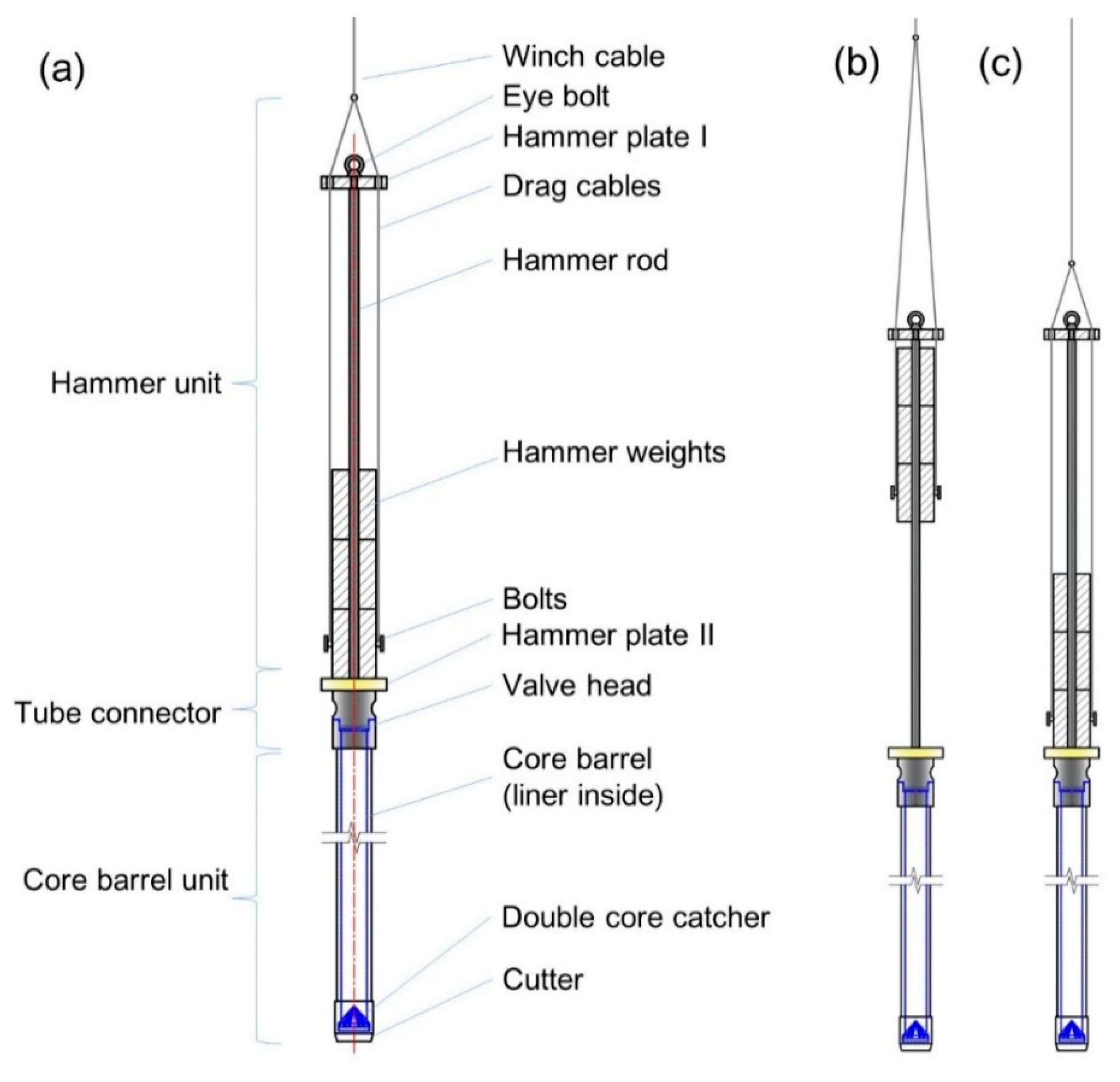
The BAS/UWITEC percussion corer was developed by the BAS in collaboration with UWITEC [8]. It consists of a hammer unit, the valve head, and a core barrel unit (Figure 13). The maximum diameter of this corer is 14 cm and the 3 m long version with three hammer weights makes a total of ~130 kg. The corer was designed to pass through a ~30 cm wide access borehole. The double-tube core barrel unit consists of an outer barrel (ID/OD 64/70 mm) made of stainless steel, a 3 m long UWITEC PVC liner (ID/OD 59.5/63 mm), a double layered orange peel core catcher, and a cutter nose (ID/OD 59/74 mm). This corer can be deployed to core 6 m long sediment samples if it is equipped with a 6 m double-section core barrel. Lowering, lifting, and downhole coring procedures can be manually accomplished by a single winch cable through surface operations.
Figure 13. (a) Structure of the BAS/UWITEC manually operated percussion corer: (b) Hammer lifting state and (c) hammer lowering state.
This BAS/UWITEC manually operated percussion corer was used during the 2011–2012 austral summer in the hot-water drilling project at Larsen C and George VI ice shelves. A total of 1160 cm of sediment cores were recovered with a maximum penetration of 290 cm [14,57,58]. BAS recovered several cores using the BAS/UWITEC corer, including (i) cores with lengths up to 115 cm from beneath Pine Island Glacier during 2012–2013 [59,60]; (ii) a 135.5 cm long core from FNE2 drilling site during the 2016–2017 season; (iii) a 152 cm long core from FNE3 drilling site during the 2016–2017 season; (iv) a ~10 cm long coarse gravel core from beneath Rutford Ice Stream drill site, where ice thickness was 2152 m during the 2018–2019 season [61], respectively. This corer was deployed at several hot-water boreholes (~40 cm in diameter) at the Ekström ice shelf between November 2018 and January 2019 as part of the Sub-EIS-Obs project [45]. Eight coring attempts resulted in 7 cores with a total length of ~826 cm and single core lengths of up to 200 cm.
Another UWITEC percussion corer deployed in the Antarctic is the UWITEC KOL Kolbenlot percussion piston corer, a commercial product used for lake sediment coring, working at depths of no more than 140 m [46]. This 2 m long corer is manually operated from the ice surface [62]. Three overlapping 2 m long cores with a total penetration depth of 3.76 m were obtained at the Subglacial Hodgson Lake core site (72° 00.256′ S, 68° 29.022′ W), where the ice was 3.7 m thick and the lake bed was located 93.4 m below the ice surface [22].
JLU Manually Operated Hammer Corer
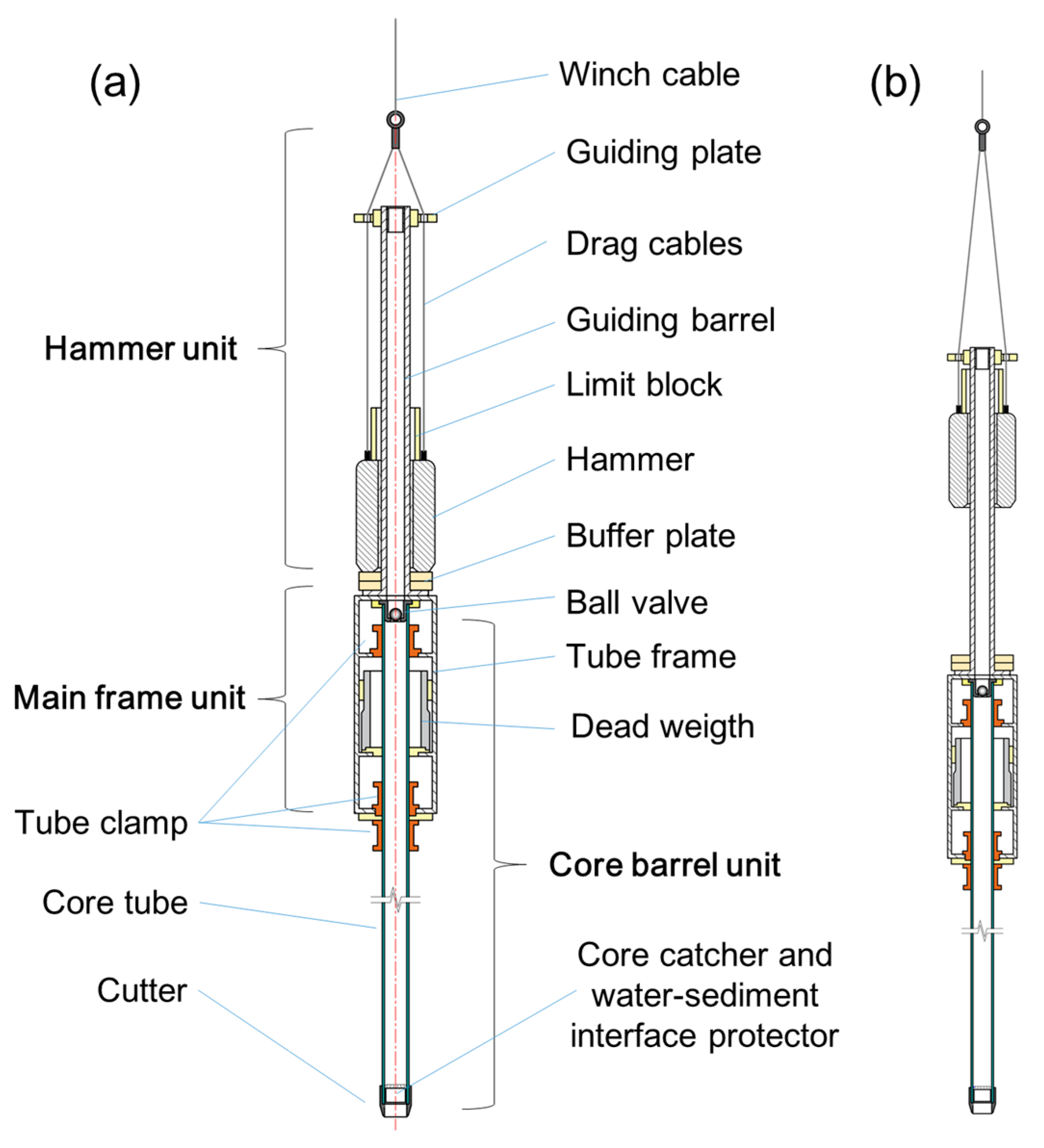
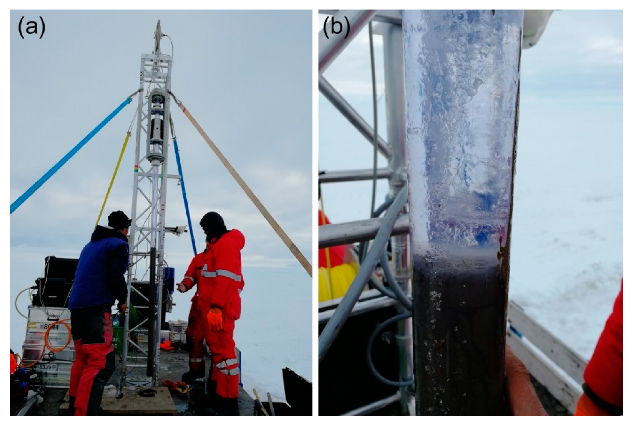
The JLU (Jilin University, China) manually operated hammer corer was used at the Neumayer Station III in Antarctica to obtain a long core sample (>100 cm) with an undisturbed water–sediment interface. The corer consists of a hammer unit, the main frame, and a core barrel unit (Figure 14). The maximum diameter of this corer is 23 cm and it weighs ~130 kg, including its 45 kg hammer. The single core tube (UWITEC liner) measures 59.5/63 mm (ID/OD) excluding the outer barrel, and the cutter (ID/OD 59/66 mm) with the core catcher and the water–sediment interface protector are attached at the lower end of the core tube. The coring procedure is generally the same as that for the BAS/UWITEC, except for an additional step included to preserve the water–sediment interface. The water–sediment interface can be kept at an undisturbed state in the liner, even after the corer is lifted to ice surface. The JLU manually operated hammer corer was deployed at the Ekström ice shelf between November 2018 and January 2019 as part of Sub-EIS-Obs project [45] and it successfully obtained a 128 cm long core with a well-preserved water–sediment interface (Figure 15).
Figure 14. (a) Structure of the JLU manually operated hammer corer and (b) the hammer lifted state.
Figure 15. (a) The JLU manually operated hammer corer lifted with 130 cm core sample and (b) the well-preserved water–sediment interface (photographs were taken by Y. Li).
NIU Percussion Corer
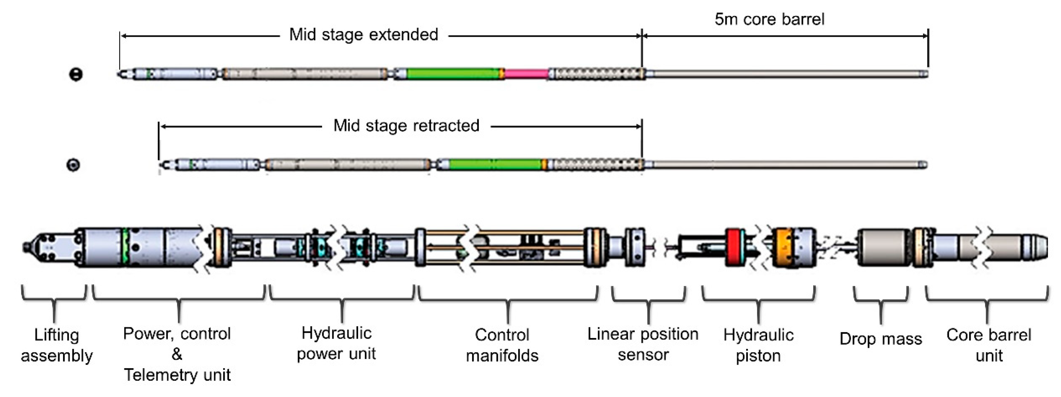
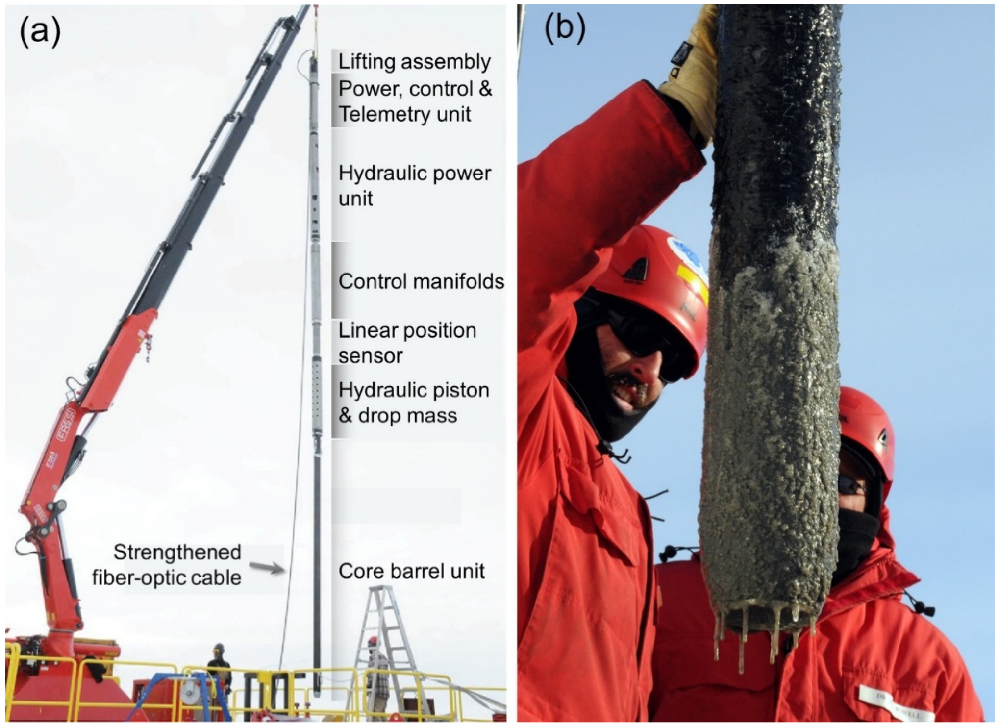
The SLW (Subglacial Lake Whillans) hydraulic percussion corer (Figure 16) or NIU (Northern Illinois University) percussion corer was designed by S. Vogel and DOER-Marine to obtain deeper, hard, and over-consolidated sediment cores, such as subglacial till cores [1,33]. The corer is designed to be sterilized and it measures a total length of ~14 m and has a ~220 mm maximum OD, including a 5 m long core barrel with ~100/141 mm ID/OD. It is powered by a hydraulic system (motor, piston, for example) that includes a ~900 kg percussion drop mass; a power, control, and telemetry unit; and a lifting assembly. A smart Kevlar-reinforced fiber-optic cable (4500 kg load ability) connected to the multipurpose winch is used to deploy the corer.
Figure 16. Structure drawing of the NIU percussion corer [33] (Reproduced with permission from WISSARD, 2019).
To ensure that the pullout strains between core barrel and sediments do not exceed the cable’s maximum tension capacity, the corer can enable a ‘hydraulic helping’ mode. First, the hydraulics can be commanded to force pressurized water down to the gap between liner and core barrel, then, the water exiting via jet holes in the core cutter head is forced up the outside of the core barrel to decrease the friction between the corer and sediments [1,8,33].
This corer was deployed to the hot water drilling site at the Subglacial Lake Whillans (84.240° S, 153.694° W) in late January 2013 within the WISSARD project (Figure 17). Unfortunately, the corer’s working modes failed to work as designed due to a malfunction in the surface smart winch. Eventually, used as a gravity corer, it was finally able to collect a 0.4 m long gravity sediment core [1].
SLE Percussion Piston Corer
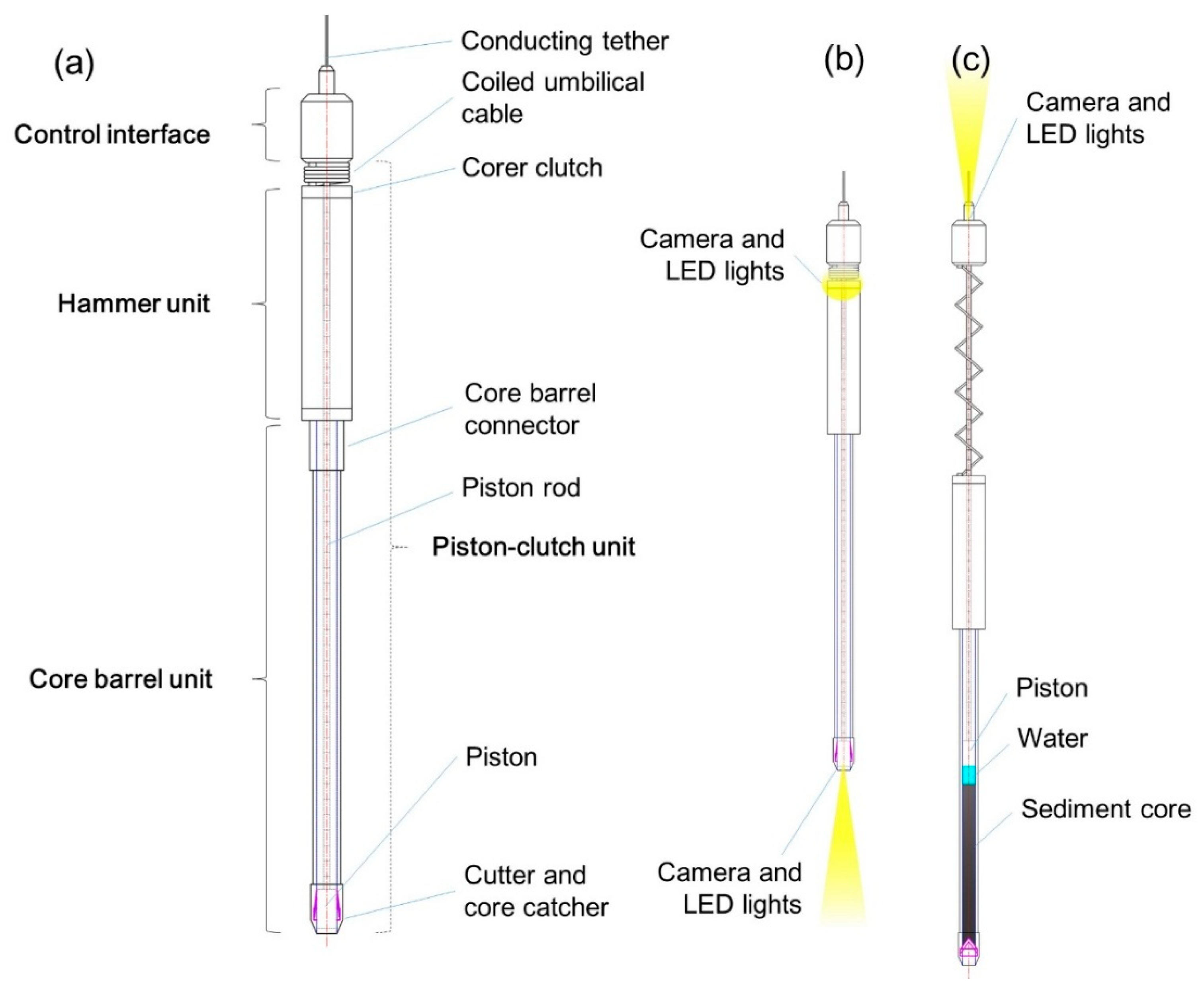
The SLE percussion piston corer (Figure 18a) was designed and manufactured by UWITEC and BAS [7]. The corer is designed to be sterilized and has a length of 5.8 m and a maximum diameter of 20 cm [7,8]. This corer was the first ‘real-time visual corer’ to study the Antarctic subglacial sediment environment. It consists of five main parts, including a control interface, the hammer, the core barrel, the piston, and the piston-clutch [8]. The control interface contains power converters, control electronics, and communication modems. The hammer has a linear motor drive hammer mechanism sealed in the pressure chamber. The core barrel (3-m long version), liner, cutter (hardened steel) and double-layered orange peel core catcher were borrowed from the UWITEC corer design [7]. The corer’s clutch can prevent the piston from moving further to deform the sediment core when the core barrel is full or when sediment penetration has ceased [8]. Cameras are integrated with the piston, pressure chamber, and near the clutch; thus, operators working on ice surface can monitor and control the coring procedure through a conducting tether (Figure 18b,c). The coiled umbilical cable can compensate for the distance changes occurring between the control interface unit and the hammer unit during coring [8].
Figure 18. (a) The SLE percussion piston corer general structure layout, (b) lowering state, and (c) lifting state with core obtained.
This corer has been specifically and progressively designed to implement technical innovations in subglacial aquatic sediment sampling, such as controlled coring through real-time monitoring, the ability to obtain a long core with a well-preserved water–sediment interface, and the separation between the control cabin and the power cabin. Unfortunately, this corer has not yet been deployed due to the same reason [54] cited for the SLE gravity corer.
Piston Corers
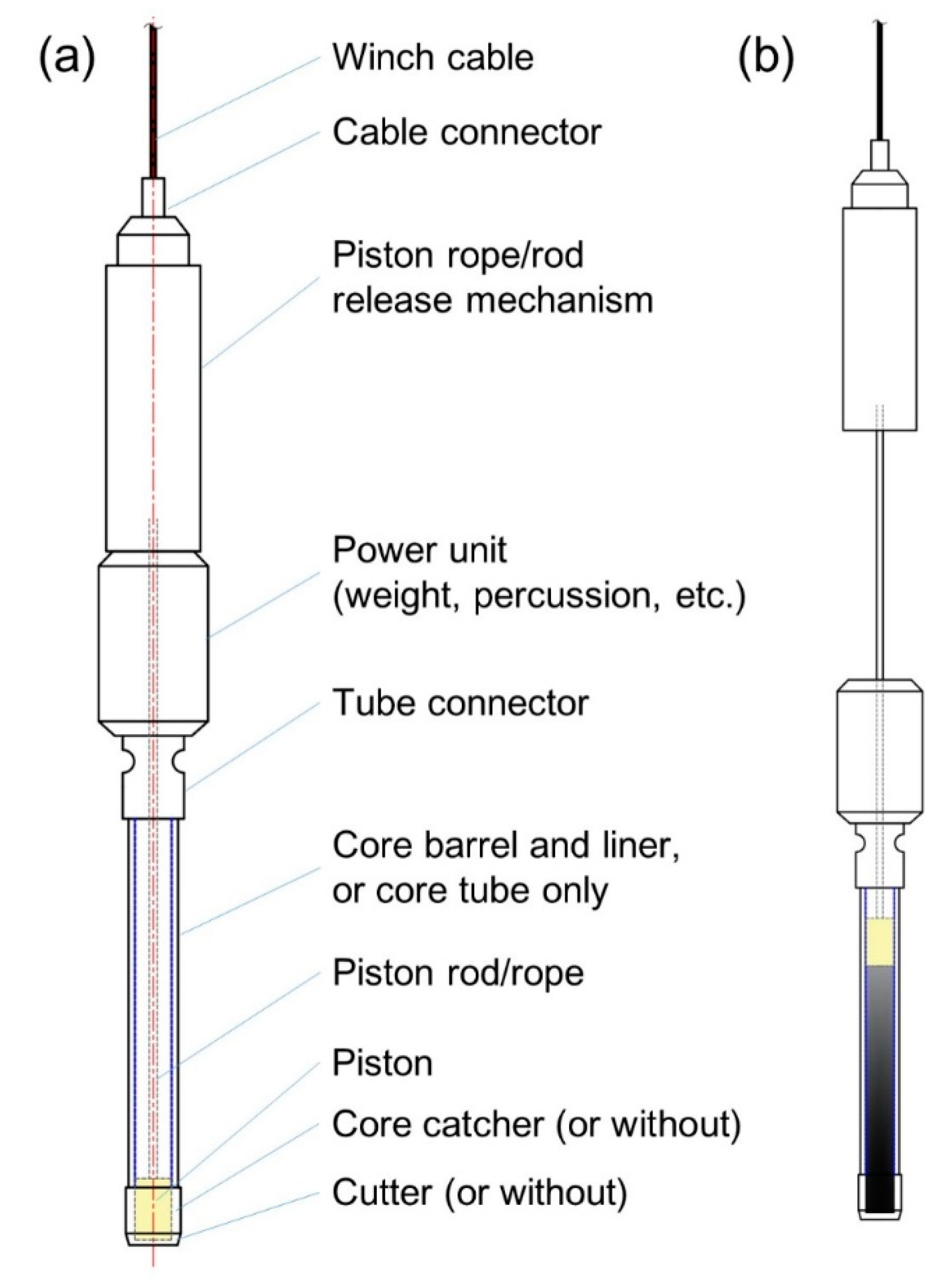
Piston coring is one of the more common seafloor or lake-floor sediment sampling methods. From the perspective of power supply modes, no corer deployed in the Antarctic subglacial sediment setting has ever been purely a ‘piston corer’. Instead, the piston units have always used additional technological units such as push coring, gravity coring, percussion coring, and vibrocoring. All of these reduce the friction between the inside wall and the sediments, and assist in the evacuation of displaced water from the top of the corer [11]. The working principle of the piston-equipped subglacial sediment corers is generally the same as that of the open water sediment corer (Figure 19).
Figure 19. (a) General layout of subglacial sediment piston corer and (b) corer state with core obtained.
In this review, we have listed only the Caltech piston corer and WISSARD piston corer as corers that can be classified as ‘pure piston’ corers. Other corers that include a piston unit have been classified based on their characteristic penetration power resource methods (e.g., the SLE percussion piston corer).
Caltech Piston Corer
The Caltech piston corer was designed and built by a California Institute of Technology (Caltech)-led team that conducted sediment coring beneath Ice Stream B (at camp UpB), West Antarctica [16]. This corer design was derived from the marine piston corer, which is 6 m long with a 50 mm liner ID. It is equipped with a cutter, a metal core catcher, and a plastic liner fitted into the steel core barrel. Several cores of up to 400 cm long [19] were recovered through about 50 hot-water-drilled access holes with an average depth of ~1030 m at Upstream B, where sediments are deposited about 600 m below sea level [8]. More detailed information about this corer’s design and its working principle were not published.
WISSARD/Caltech Piston Corer
The WISSARD piston corer (Figure 20) was based on the design of the previous Caltech piston corer. It was designed and built by the University of California Santa Cruz to collect non-deformed sediment cores at the bottom of subglacial Lake Whillans [8,33]. This borehole corer is equipped with a 3 m long core barrel with a 58 mm ID [1]. The corer is designed to be sterilized and is mainly made of stainless steel. On its upper stage, there is a tube containing a coiled Kevlar release cord that is used to dead drop the corer [8]. Several external guiding plates at the upper end of the corer increase the possibility of vertical insertion. This corer needs to be released precisely at a few meters above the lake floor, triggered by a wireline messenger [8]. The piston unit stops at the sediment surface during penetrating and lifting. This corer can obtain cores without significant compression or disturbance. The WISSARD piston corer was used to recover an 80 cm long core during the second phase of scientific operations at the subglacial Lake Whillans drilling site in late January 2013 [1].
Figure 20. WISSARD/Caltech piston corer with sediments packed at lower part [8] (Reproduced with permission from Royal Society, 2016).
Push Corers and Mini-Corers
SLE Mini-Push Piston Corer
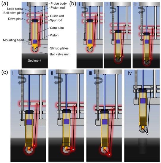
The water–sediment interface is the prime area for detecting microbial life, especially in the ultra-oligotrophic lakes such as Lake Ellsworth [23]. To be able to collect such samples, a mini-push piston corer was designed and built by the SLE team to obtain the crucial water–sediment interface in this subglacial lake. This corer is mounted on the front (lower end) of the Lake Ellsworth Probe, which is sterilized before deployment, and samples are capped upon retrieval (Figure 21) [7]. The corer is 39 cm long and is designed to obtain a composite core sample up to 22 cm long and contains the water–sediment interface [23]. All metallic parts of the corer are constructed from titanium (grade V), which, along with the nonmetallic components, ensure the validity of trace Fe analysis of all water samples [23]. The SLE probe includes a video camera and lighting system to enable continuous monitoring of the area below the probe. After the sediment surface is sighted and assessed visually by the surface operator, the corer is then deployed to start coring [8]. The coring deployment by itself takes approximately 3.5 min with a penetration speed of 1 mm/s [23]. To simplify the description, the whole coring process is divided into two phases, the penetrating (Figure 22b) phase and the ball valve sealing phase (Figure 22c). During the penetrating phase, the lead screw drives the whole corer assembly to penetrate the sediment. After the corer reaches the target penetration depth, the corer assembly automatically initiates the sealing phase, i.e., the lead screw continues to rotate, moving the ball drive plate down, which rotates the ball valve by 90° and seals the core tube end [23].
Figure 21. (a) Position of the SLE mini-push piston corer integrated in the Lake Ellsworth Probe and (b) the mechanical structure of the SLE mini-push piston corer [23] (Reproduced with permission from Royal Society, 2018).
Figure 22. SLE mini-push piston corer: (a) Mechanical layout of the corer parts, (b) penetration procedure, and (c) ball valve sealing procedure.
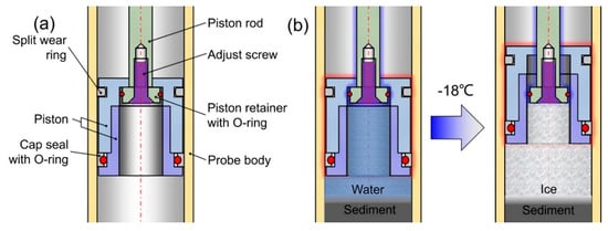
The piston keeps a static position relative to the probe body (mounting head) during the whole coring process, thus preventing fluid intrusion from the outside [23]. Since the core water freezes during the probe’s ascent back through a cold (approximately −18 °C) air-filled section, the piston was designed with a volume compensation mechanism (Figure 23) that can compensate for the water volume change when water inside the core tube freezes.
Figure 23. (a) Mechanical structure layout of the piston unit. (b) Principle and procedure for how the piston compensates volume change of frozen water.
This corer passed testing on artificial laboratory sediments as well as deep-marine sediments (1020 m water depth). The results show that this corer can obtain samples in all the sediment types assessed, and the piston unit and other mechanisms worked well [23]. Unfortunately, the BAS hot-water drill failed to access Lake Ellsworth in 2013 and the corer has not been tested in the Antarctic.
2.4.2. ANDRILL String Mounted Push Corer
A push corer inner tube assembly was deployed at the AND-1B site (77°53′22″ S, 167°5′22″ E) by the ANDRILL drilling team in October 2006, using a sea riser and a drill string which were lowered to within a few meters of the seafloor. Different from the AWI gravity corer previously deployed at same site, the push corer is not cable-operated but is installed on the drill string and is directly ‘pushed’ into the sediment without rotation or the use of drilling mud. This corer is 1.6 m [35] long and it is attached to the end of an 83 mm diameter drill bit [15]. Using this method, four cores, varying in length from 33 to 156 cm, were collected by the drill string-mounted ODP (Ocean Drilling Program) liner. Most cores were lost during the lifting operation, resulting in only 216 cm of sediment cores obtained from sediments at depths of between 0.70 m and 10.18 m [35]. The reason we list this non-cable-suspended corer here is to provide a results contrast with the AWI gravity corer that was deployed at the same access borehole.
2.5. JLU Self-Synchronous Vibrocorer
As a consequence of the penetration depth limit of sediment coring tools used for Antarctic subglacial aquatic sediment sampling, a narrow bore corer with a ‘self-contained power unit’ is required to obtain deeper cores [11,22].
Vibrocoring is a simple and efficient technique for obtaining high–quality sediment core samples in a variety of configurations and sizes [64,65]. A vibrocorer is sometimes considered as a high-frequency and low-amplitude hammer corer; however, this view is incorrect because the working principles are different. The vibrocorer utilizes the ‘vibrating liquefaction effect’ [65] of water-saturated sediments, i.e., the sediments adjacent to the core tube can be re-orientated to a ‘shear strength lost’ status, then the core tube can be pushed into the sediment using the weight of the vibrocorer itself [66,67].
The first Antarctic subglacial sediment vibrocorer, designed and built by JLU, aimed to address the technical gaps involved in obtaining long sediment cores. To cope with the access borehole size limitation problem (the main reason that vibrocoring had not been applied yet), the JLU vibrocorer is equipped with a cylindrical vibro-head that gives the whole corer a maximum outer diameter of 27 cm. There are two versions of the JLU vibrocorer. One is designed as a cable power supply corer (Figure 24a) for the hot water drilling project of CHINARE (Chinese National Antarctic Research Exploration) and the other is designed as a self-powered corer for the Sub-EIS-Obs hot water drilling project of AWI (Figure 24b). Both of these corers have been tested in the laboratory with satisfactory results. Sediment cores with lengths of up to 3 m contained sandy mud and hard clay [27].
Figure 24. The JLU vibrocorer: (a) the cable powered CHINARE version and (b) the AWI version with self-contained batteries.
The JLU vibrocorer was first applied underneath the Ekström Ice Shelf f during the 2017–2018 season as part of Sub-EIS-Obs exploration project. The general structure of the JLU vibrocorer is shown in Figure 24b. The core tube unit was originally designed to collect 3 m or 6 m cores with a diameter of 106 mm. The cutter OD is 130 mm and the whole corer is 4.7 m long and weighs 256 kg, including the 3 m core barrel. A self-synchronous vibrator first was designed and tested. This can produce a vibration frequency of 50 Hz and a maximum acceleration of ~300 m/s2. The vibrator is powered by self-contained batteries and the vibration can be started on a time-delay. During the 2017–2018 season, the corer was deployed through the ice shelf twice but no core was retrieved because the load cell on the tripod frame top was broken. Without accurate load parameters, the corer was deployed relying only on information on cable depth and the time to set the vibration delay switch. The corer was able to reach the sediment layer; however, because it fell on its side at the seafloor, the only sediments collected were those that adhered on the core catcher and the spring buffer unit.
To improve the corer’s penetration ability, three aspects have been modified as follows: (1) It was equipped with a more powerful vibro-head, powered by standard Makita tool batteries, that can work on intermittent vibration modes; (2) the custom-made core barrel (ID/OD is 106/124 mm with liner inside) was replaced with the conventional UWITEC core barrel (ID/OD is 59.5/70 mm with liner inside), thus reducing the cutting area by half; and (3) a tube guider was added. The improved JLU vibrocorer was redeployed underneath the Ekström Ice Shelf f during the 2018–2019 working season, also as part of Sub-EIS-Obs exploration project. Unfortunately, after being deployed on its first vibrocoring run, it was not possible to lift the corer from the sea floor. At that time, the system had been deployed for around 20 min, to await the start of the vibration. After more than 12 h of continuous attempts to lift the corer, using increasing loads on the winch, the 3 mm diameter Dyneema cable broke with a tension load of 1500 kg (i.e., the specified maximum load) and the deployed corer was lost. By that time, the cable had frozen to the borehole wall, which freezes at a rate of around 5 mm/h (i.e., 1 cm/h in diameter).
DBTS Drill (Corer)
After the Russian team reached the surface of the subglacial Lake Vostok in 2012 and 2015, there has been anticipation in collecting the bottom sediments because these may contain unique information regarding the geology, natural environment, and climate changes in Central Antarctica [30,68]. In 2017, a cable-suspended DBTS (Dynamically Balanced Tool String) coring tool was proposed by the Saint-Petersburg Mining University. It has been especially designed to be sterilized for sediment coring in the subglacial Lake Vostok through a deep 5G borehole [30].
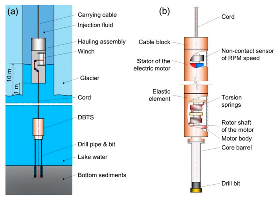
This corer is lowered to the lake surface by a hauling assembly using a carrying cable connected to a surface winch (Figure 25a). The hauling assembly works as a transporter and contains a small winch insert with heating elements. After the hauling assembly reaches the working area 1–2 m above the lake surface, the corer is lowered down by a 1 mm diameter thin cord coiled around the capstan of a small winch. Meanwhile, the heating elements operate to mitigate against the liquid column re-freezing. After the corer touches the sediment layer, the lower drill pipe with the drill bit starts rotation and drilling [30].
Figure 25. General layout of Lake Vostok sediment sampler: (a) Operation scheme of the sampling deployment and (b) the sampler driven by the DBTS.
The main feature of this corer is the DBTS system (Figure 25b), a two-mass oscillatory electromechanical system with reciprocating and rotating motions with two degrees of freedom (rotation and penetration). A drilling system with a DBTS can perform rotary drilling without any external support on the borehole walls to bear the counter torque [30].
This corer has two optional operational modes, a self-driven mode and a controlled mode, which is operated from the surface. In the self-driven mode, all the operations are carried out automatically and there is no communication between the research module and the surface personnel [30]. Laboratory tests of the DBTS motor drive have been carried out on simulated and physical models, and have confirmed the feasibility of the DBTS system. It has been suggested that a DBTS with a diamond drill bit can even drill through a solid brick [30].
Unidentified Corer
During the 20th Soviet Antarctic Expedition in 1975, one 28 cm core was collected under the Novolazarevskiy Ice Shelf at a site (70°14.2′ S, 11°51.4′ E) with 375 m thick ice. The ice surface was 203 m above sea level [39]. However, the depth of the sea bottom and the core type were not published.