High-frequency operation of WPT systems leads to miniaturization of the components and a higher efficiency. For this reason, various soft-switched topologies such as Class D, E, EF, etc., are used to operate the WPT systems at high frequencies in the megahertz range. WBG and ultra-WBG devices can be used for very high frequency operation. Compensation topologies reduce the VA rating of the transmitter and can also infer voltage source or constant source characteristics to the inverters. Constant current source inverters are particularly useful when using multiple receivers since they ensure decoupled power transfer to the receivers.
2.2. Compensation Networks
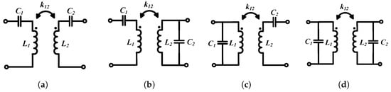
The inductance of the coil in the receiver circuit of the WPT system needs to be compensated for to increase the efficiency of the system, and the inductance of the coil in the transmitter circuit needs to be compensated for to reduce the VA rating of the input power. There are four basic compensation topologies, namely series-series (SS), series-parallel (SP), parallel-parallel (PP), and parallel-series (PS), based on the connection of the resonant capacitance, as shown in Figure 6. Current-driven topologies are used with series resonant receiver circuits and voltage-driven topologies are used with parallel resonant receiver circuits. With a series resonant receiver coil, the benefit is that even if the load resistance varies or the coupling coefficient between the coil changes, the series-tuned circuit still reflects a purely resistive load to the primary coil. With parallel resonance on the receiver, when the load resistance changes, it reflects reactance along with resistance back to the primary, and hence the circuit is detuned and the soft-switching capability might be lost. Hence, series resonant tuning is preferred on the receiver side.
Figure 6. Basic capacitive compensation topologies: (a) SS, (b) SP, (c) PS, and (d) PP.
1. Introduction
The concept of transferring power without wires has been around for over a century. It was first demonstrated by Nikola Tesla in 1891 [
1]. He used Michael Faraday’s discovery of electromagnetic induction, in which a current-carrying wire induces a current in adjacent conducting wires [
2]. Based on Tesla’s theoretical framework and the advances in fast and more efficient power electronic components (such as silicon, silicon carbide, and gallium nitride devices), near-field WPT has become a reality [
3]. Tesla proved that wireless power transmission could be made more efficient if the coils transferring power were in resonance. To operate the system in resonance, the frequency of operation needed to be increased. This required high-frequency switched-mode power converters and conducting wires which have a low AC resistance (e.g., Litz wires [
4]). Their inventions led to advances in medical implants with wireless charging in the late 1980s [
5,
6], inductive power pickup systems, and charging of EVs (electric vehicles) in the 1990s [
7,
8]. Ever since mobile phones were invented in the 1990s, researchers have been trying to find techniques to charge them wirelessly [
9,
10,
11]. WPT aids in excluding bulky wires which not only makes it more convenient for users, but also makes it better for the environment [
12]. With enhanced convenience and frequency of charging with WPT, the capacity of the energy storage systems can be decreased, as well as the size, weight, and cost of the device. Furthermore, transmitters can be easily embedded into furniture, automobiles, computer monitors, etc.
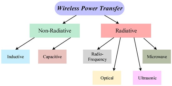
WPT can be broadly classified into radiative and non-radiative methods as shown in
Figure 1. Radiative power transfer takes place over long distances (which are much greater than the antenna size) using electromagnetic waves [
21]. Some examples may include power transfer through radiofrequency [
22], microwave [
23], optical [
24], and ultrasonic [
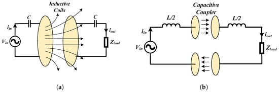
25] technologies. However, owing to the omnidirectional nature of the power transfer, the overall system efficiency is quite low in this method. Hence, non-radiative methods are preferred for near-field applications. Non-radiative methods rely on magnetic or electric field coupling, which includes capacitive and inductive wireless power transfer, as shown in
Figure 2.
Figure 1. Classification of techniques for wireless power transfer.
Figure 2. Wireless power transfer using (a) inductive coupling and (b) capacitive coupling.
Capacitive power transfer (CPT) takes place using time-varying electric fields. Electric fields start and terminate at the conductive plates in CPT because of positive and negative charges on the plates. As a result of the constrained E-field, CPT systems do not induce eddy currents in nearby objects and do not require ferrites, which reduces the size and weight of the system. Furthermore, CPT systems [
26,
27,
28,
29,
30,
31,
32] are more tolerant of misalignment and have fewer EMI shielding requirements. Inductive power transfer (IPT) occurs by using time-varying magnetic fields. Due to the absence of magnetic monopoles, magnetic field lines flow through the coils and loop back to the source and hence this magnetic field path needs to be monitored and guided. In IPT, the voltage induced across the receiver coil depends on the permeability of free space, whereas in CPT, the displacement current that is going to flow through the coupler depends on the permittivity of free space. The biggest benefit of using magnetic fields for wireless power transfer is the difference between the permeability and permittivity of free space, where the former is five orders of magnitude higher than the latter. This shows that for the same size of couplers and distance between them, the intensity of electric fields needs to be many orders of magnitude more to produce comparable displacement currents in CPT, as induced voltages are produced in IPT [
28]. Furthermore, if the dielectric between the two plates in a CPT system is air, the capacitance value is relatively low (a few pF). This makes the system very sensitive to parameter variations such as parasitic capacitances near the plates or interwinding capacitances of the compensating inductors [
27]. Hence, the plate sizes need to be larger or the air gap between them must be reduced. For these reasons, IPT is preferred for portable electronic applications with multiple receivers where the distance between the transmitter and receiver needs to be greater.
Both capacitive and inductive power transfer can be made more efficient by operating the WPT systems in the megahertz range. A higher frequency of operation also miniaturizes the magnetic components and improves the power density of the system. Silicon (Si) MOSFETs are not preferred for MHz frequency operation because of higher switching losses. This is due to slower turn-on and turn-off times caused by higher values of gate capacitances. Hence, wide band gap (WBG) devices such as silicon carbide and gallium nitride are preferred for these applications since they have a higher electron saturation velocity [
33].
Compared to the GaN MOSFET, SiC has a lower
Rds,on at room temperature and can operate at much higher temperatures than Si and GaN MOSFETs as they have lower leakage currents and higher thermal conductivities. The
Rds,on of GaN MOSFETs varies significantly with temperature variations [
33].
WPT has been used in a wide range of applications including charging of portable electronics [
36,
37,
38,
39,
40], electric vehicles [
41,
42,
43,
44,
45], electric drones, automated guided vehicles (AGV) [
46,
47,
48,
49,
50], medical implants [
51,
52,
53,
54,
55], plasma generation [
56], and automation in factories [
57,
58,
59,
60].
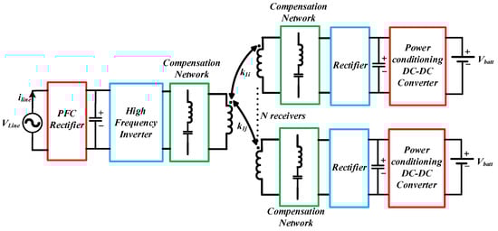
The basic architecture of a WPT system to power multiple portable electronic devices is shown in
Figure 3. From the AC supply line, the low-frequency AC voltage is first converted to a DC using a power factor correction (PFC) rectifier [
62,
63]. The DC voltage is then converted to AC using a high-frequency inverter or power amplifier topology, which then drives the transmitter coil through a compensation network. The power sent by the coil using magnetic fields is picked up by the receiver coils. After passing through the compensation network, the receiver current is rectified and conditioned using a DC-DC converter based on the load requirement. To reduce the number of components and decrease the losses in the power electronics, the PFC rectifier and the high-frequency inverter stages can be combined into one AC-to-AC conversion stage [
64]. The rectifier can also be combined with the power conditioning unit on the receiver to form an integrated active rectifier [
65], which can provide constant voltage or constant current control for charging the batteries of the portable electronics.
Figure 3. Architecture of a WPT system with multiple receivers.
2. Wireless Power Transfer System Modeling and Efficiency Optimization Techniques
Similar to the modeling of resonant converters, WPT systems can be analyzed in the frequency domain [
69,
70,
71,
72] and tim domain [
73,
74]. Time-domain modeling gives more accurate results and can model the discontinuous conduction modes (DCM) of the WPT system. However, the application of time-domain modeling requires information about the equivalent states of the circuit which can be obtained using simulations or through experiments. If the series resistances of coils, ESR of capacitors, and on-state resistances of the semiconductors are added to the analysis, the differential equations can have exponential terms in them which can make the solutions quite involved and closed-form solutions might be unattainable. Furthermore, time-domain modeling cannot be extended to analyze multiple receivers, with cross-coupling among them, since closed-form solutions do not exist [
75]. Hence, the frequency-domain model of such systems is more beneficial. The most widely used technique is the first harmonic approximation (FHA). The simple closed-form solutions obtained from FHA can give an overall idea about the system. The voltages and currents in the system are approximated as sinusoids with one frequency. However, this technique might not be optimum for design since it may lead to overdesign or underdesign of components in the case where more dominant harmonics are present in the voltage and current waveforms. Hence, considering harmonics on both source and load sides [
69,
70,
71] is beneficial for design purposes and can easily be extended to multiple receivers.
.1. Model of a WPT System Using Series-Series Compensation
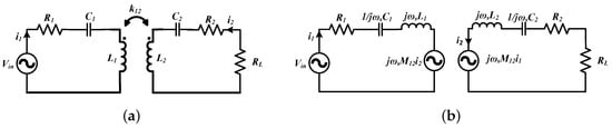
A simplified lumped parameter model of a WPT system using FHA is shown in
Figure 4a. The transmitter consists of an AC voltage source, a compensation capacitor, and the transmitting coil. The AC voltage source is most commonly a high-frequency inverter or a power amplifier which drives the transmitter coil. The most used compensation network is the series-series configuration but some other widely used networks include LCL [
77], LCC [
78,
79], LC/S [
80], etc. The series resistance is the sum of coil resistance, ESR of compensating capacitors, and any resistance from the source. The receiver comprises a coil, a compensating capacitor, and a load. The load can be AC or DC. In case it is a DC load, which is typically the case with battery charging applications, then the load is preceded by a rectifier and a power conditioning unit (typically a DC-DC converter). The coupled inductance can also be modeled as two dependent voltage sources on the transmitter and receiver as shown in
Figure 4b. Other commonly used models of the WPT coils are the T-transformer network and the cantilever model; however, the coupled inductor model is the most widely used.
Figure 4. Lumped parameter model of inductive WPT systems with (a) soils modeled as coupled inductors and (b) effect of mutual coupling modeled as dependent voltage sources.
2.3. Maximizing Power Transfer between the Transmitter and Receiver
Maximum power transfer takes place in a WPT system when the source impedance is matched with the load impedance. The maximum power transfer and maximum energy efficiency do not necessarily happen simultaneously. The maximum energy efficiency occurs when the source impedance is minimized and the load impedance is optimized, and they are not necessarily equal. As a result of impedance matching, the efficiency of the system under the maximum power transfer approach cannot be above 50%
[
85]. Hence, this technique is suitable only for very low power applications (<1 W) which require sufficient power delivery over a greater distance.
2.4. Efficiency Optimization Techniques
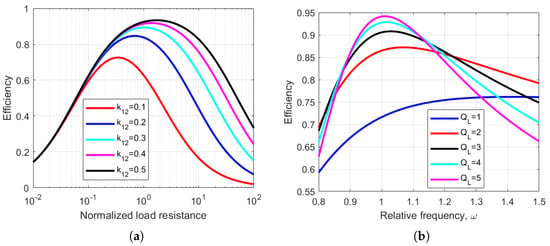
Most common loads of WPT systems such as batteries do not have a constant resistance. During battery charging, the load current and the equivalent load resistance vary with time. The efficiency of the system is optimized at a specific load resistance. This can be observed in Figure 8, where the efficiency of a WPT system has been plotted as a function of normalized load resistance for various values of coupling coefficients. Four commonly used techniques can transform the reflected load to the optimum value.
Figure 8. Efficiency of the WPT system as a function of (a) normalized load resistance, RL, for different k12 and (b) relative frequency for different loaded quality factors and k12 = 0.4.
2.5. WPT Systems with Multiple Coils
2.5.1. Intermediate Multiple Coils Acting as Repeaters or Domino Resonators
Multiple resonators or repeaters can be added in between transmitter and receiver coils in WPT systems for different applications. This enables transmission of power over larger distances or along a curved path such as in the case of a robot arm. The two main reasons for such configurations are:
- 1.
-
Multiple intermediate coils introduce more degrees of freedom which can be utilized for improving efficiency or making the wireless link less sensitive to coupling variations.
- 2.
-
The intermediate coils can also act as effective impedance matching elements [
90] on both the source and load sides.
2.5.2. Multiple Transmitter Coil Systems
Multiple transmitter coils are mostly applied in two areas: (a) dynamic WPT and (b) systems that require misalignment tolerance. In dynamic WPT systems, the receiver is in motion. Multiple transmitter coils are connected to one power source and have to be powered effectively based on the location of the receiver. The current flows in the transmitter coils to which the receiver is aligned, while other transmitter coils are not charged. By using multiple transmitter coils, one can also generate a nearly uniform magnetic field over a surface, allowing some tolerance to misalignment of the receiver [
85].
2.5.3. Multiple Receiver Coil Systems
In some WPT applications, multiple receivers are needed to be powered simultaneously from a single transmitter system. As shown in
Section 2.1, adding more receivers can improve link efficiency. However, the addition of multiple receivers reduces their coupling coefficients with the transmitter because of spatial constraints. Hence, quality factors of the coils need to be increased, which can be achieved by operating the system in the MHz range. In practice, there are many uncertainties with multiple receiver systems, such as variations in the coupling and load and addition or removal of receivers. Therefore, it is necessary to have a robust system with proper design and control. The most common control objective is to maximize the system’s efficiency while maintaining voltage regulation at the output. To ensure voltage regulation at the output of the receivers, a DC-DC converter is commonly used [
91,
92]. Voltage regulation can be maintained with wide variations in load or coupling if the input voltage to the system is sufficiently large. However, a large input voltage leads to inefficient operation of the system.
3. Inverter, Rectifier, and Compensation Topologies for Wireless Power Transfer
3.1. Inverter Topologies
To ensure the high efficiency of the inverters, losses in the semiconductor devices must be minimized. The major sources of power losses in semiconductor devices are conduction losses and switching losses. When the switching frequency is increased, the optimal load resistance in Equation (
6) also increases. Thus, for a given output power, one can operate at a higher voltage and lower current on the transmitter side. This reduces conduction losses on the switch, since they are proportional to the square of the current. Switching losses are proportional to the frequency of operation and can be significant at MHz frequencies. However, switching losses can be almost eliminated using soft-switching techniques. There are several types of DC-AC power inverters in the MHz frequency range which can achieve soft-switching such as the class D, class E, and class EF inverter topologies.
3.1.1. Class D Topology
The two switches have a complementary operation to one another, with a suitable dead time, and produce a square wave voltage across the bottom switch. Class D inverters are used mainly in low-power systems and are widely used with the Qi standard. They can operate over a large load range with soft switching if the switching frequency is above the resonant frequency of the transmitter, i.e., the resonant tank current is inductive (lagging) with respect to the tank input voltage. This increases the VA requirement of the power source. Another disadvantage of the Class D topology is the use of more switches (two for half-bridge and four for full-bridge).
3.1.2. Class E Topology
The Class E circuit has only one switch that is low-side referenced, which makes it easier for driving the inverter at high frequencies [
111]. If the load network is slightly inductive, the standard Class E circuit allows soft switching. A major drawback of the Class E topology is that the voltage stress across the switch is nearly
3.56
times that of the input voltage when operating under optimum conditions. Furthermore, in the Class E topology, the transmitter coil current must flow through the transistor. This switch current can be reduced by using a parallel resonance. One way to minimize the VA rating of the switch is by using a “semi resonance” tank [
112].
3.1.3. Class EF Topology
A resonant branch,
L2and
C2, is added across the switch, which offers an extra degree of freedom to the designer to achieve ZVS throughout the entire load range. The extra LC resonant tank also reduces the voltage and current stresses across the switch and improves the efficiency of the inverter as well as increases the power handling capability. The added network can be tuned to twice the switching frequency (or 2nd harmonic), in which case the modified topology is known as the Class EF2 or Class
ϕ2 inverter [
114].
3.2. Rectifier Topologies
From the time reversal duality [
115] concept, rectifier topologies can be derived from inverter topologies and vice versa. For low current applications (<2 A), rectifiers are normally made with diodes, which could lead to significant losses due to hard switching and reverse recovery. Hence, soft-switched (or resonant) topologies which do not have high semiconductor stresses need to be used.
3.3. Transmitter Topologies with Constant Current Output
In multiple receiver systems with a voltage-source-type transmitter, the change in load on one receiver affects the amount of power delivery to the others. This is because the power delivery to each receiver is directly proportional to the reflected resistance on the transmitter. The current in the transmitter varies with changes in the reflected resistance with movement or load variations in one receiver, and hence the power transferred to all the receivers can change. Ideally, if the transmitter is a current source and the cross-coupling among the receivers is negligible, the power delivered to each load is only dependent on the impedance reflected to the transmitter. Hence, a decoupled power transfer to the receiver loads can be ensured by using a constant current topology on the transmitter side.
4. Coil Design
4.1. Improving Coupling Coefficient between Coils
The coupling coefficient between WPT coils depends on the coil shapes and sizes, the distance and alignment between them, and the type of material used for the conductor. Circular coils are the most common form of WPT coils because of their symmetry and ease of fabrication. The self-inductance of circular spiral coils can be calculated using the circular loop approximation [
119]. The mutual inductance between the coils can be calculated by modeling the circular spirals as a set of filamentary circular loops [
120]. Other common coil forms include square and rectangular types. Simple expressions for planar spiral inductances (square, hexagonal, octagonal, and circular) have been derived in [
121] using a modified Wheeler formula, current sheet approximation, and data fitting. The expressions were found to be accurate within a
5%error margin. The self-inductance of the coil required for a particular application also determines its size. Some applications also have geometric constraints that the coils must adhere to. For example, the receiver coil size in phones and wearables depends on the space available inside the enclosure. The coupling coefficient between coils can be measured using a two-port network analyzer.
4.2. Improving the Quality Factor of Coils
The quality factor of the coil can be improved by reducing the AC resistance of the windings. Based on the operating frequency, the winding conductor can be solid, foil, tubular, or Litz. High-frequency eddy currents induced in a current-carrying conductor at high frequencies can cause conduction losses. Eddy currents can be induced by time-varying magnetic fields. At high frequencies, currents mostly flow near the surface of the conductors (depending on the skin depth at that frequency), leaving the inner part with almost zero current flow. This phenomenon increases the AC resistance of the conductor and is called the skin effect. When the radius of the conductor is smaller than the skin depth, current flows uniformly through the cross-section of the wire. The flow of current in close-by conductors often restricts the distribution of currents in the wires of the coils to smaller regions. This phenomenon is called the proximity effect and it increases the effective resistance of the coils, which increases with frequency. Tightly wound coils with a very low pitch between the turns have a low quality factor due to the prominence of proximity losses. Foil wires are widely used in inductive WPT systems. Copper foils with a thickness close to skin depth in the MHz frequency range (copper skin depth is between 65 and 15 µm in the 1–20 MHz range) are commercially available. They can also be manufactured in printed circuit boards (PCBs).
4.3. Self-Resonant Coils
Series compensation of coils is most widely used for WPT. When designing high Q systems, the resonant voltage may be very high across the capacitors which may lead to a breakdown of discrete commercially available capacitors. One method to reduce the voltage stresses is by using large arrays of capacitors. However, this increases the cost and reduces the power density of the system. Furthermore, it introduces stray impedances, especially for high Q coils when the capacitance required is in the low pF range. Another approach is to use the self-resonance of the coil, where the intrinsic electric field of the coil resonates with the magnetic field. The analysis and design of a series self-resonant coil has been demonstrated in [
126], where two identical planar coils were separated by a layer of dielectric material. One terminal of each coil is connected to the AC source while the other terminals are left open.
4.4. Omnidirectional Wireless Power Transfer
Planar transmitter coils produce magnetic fields in a fixed direction. Hence, the movement of the receiver coil from its desired location can reduce the flux linkage with the transmitter coil and diminish the power transferred to the load. To expand the positional freedom of wireless power transfer, omnidirectional wireless charging has been gaining a lot of interest over the past few years [
128,
129,
130,
131,
132,
133,
134,
135,
136]. Based on the number of sources used for the transmitter, omnidirectional WPT systems can be classified into two types:
-
Multiple power sources used for multiple transmitter coils. Based on the location of the receiver, the amplitude and phase of the coil currents are controlled dynamically. This requires complicated external control circuits for measurements and feedback and can become expensive in practice.
-
A single power source is connected to the transmitter. This technique is simpler to implement. However, the system can have blind spots where the coupling is much less.
4.5. Use of Ferrite Cores
Using soft magnetic materials such as ferrite cores is one method of increasing the coupling coefficient among the coils. The high permeability of the ferrite core can be used to shape the field produced between the coils and increase the coupling between them. Ferrites also increase the self-inductance of the coils. Ferrite materials, which have high saturation flux density, high bulk resistivity, high permeability, and low AC power losses, are beneficial for WPT systems. NiZn and MnZn are the most commonly used ferrites in WPT. MnZn has a high saturation flux density and a high permeability, while NiZn ferrite has a lower permeability and a high bulk resistivity. A ferrite with high permeability increases the magnetic energy storage per unit self-inductance of the coil. A ferrite with high bulk resistivity reduces the high-frequency-induced eddy and displacement currents. The core loss in ferrites for sinusoidal excitation depends on the frequency and magnetic flux density in the core. Hence, ferrites are popular in frequency ranges below the MHz range.
4.6. Solenoidal Receiver Coils for Multiple Receiver Systems
Spiral receiver coils placed face down on the transmitter pad lead to poor utilization of the transmitter area because of the increased surface area required for the receivers. A spiral or double-D transmitter coil can be used with solenoidal receiver coils to increase the arrangement density of the receivers [
138].
5. Foreign Object Detection
Foreign objects kept near the AC magnetic flux generated by the WPT coils can absorb power if they are of metallic or ferromagnetic nature. Induced eddy currents circulate within the materials, resulting in a conduction loss and a temperature rise. These currents increase the temperature of the foreign material and could become a potential safety concern. Foreign objects can be “friendly” or “unwanted”. Friendly foreign objects are generally parts of the charging devices that may absorb some power. Unwanted objects are external ones that are not part of the device, such as coins, keys, ornaments, utensils, etc. Some types of foreign object detection methods are given below [
85]:
- 1.
-
Power difference method—The transmitted and received power are monitored. If the difference between them is higher than a set threshold, it indicates the presence of foreign objects. In this case, the transmitter stops delivering power to the receiver circuit.
- 2.
-
Sensor method—Temperature and/or metal sensors are used to detect any anomaly in the transmission path. Anomalies detected by the sensors are communicated to the transmitter using load modulation. If the temperature sensed is higher than the threshold or there are metals present in the transmission path, the control circuit will shut down the power transmission.
- 3.
-
Transient energy decay method—The transmitter is powered for a short time and then disabled to check the rate of transient energy decay. If this rate exceeds the set threshold, the presence of a foreign object is confirmed and the system is shut down.
6. EMC/EMI Issues and EMF Safety in Near-Field Wireless Power Transfer
6.1. De-Sense Caused by In-Band Noise and Shielding in Smartphones
Every smartphone must satisfy some receiver sensitivity criteria (wireless WAN antenna sensitivity) to be approved by the FCC. The EMI noise produced by the system must be reduced at the antennae to maintain an appropriate signal-to-noise ratio. Furthermore, any shielding near the antennae can cause a degradation in sensitivity (de-sense). At low frequencies (near 110–205 kHz), ferrites used as shields reduce the receiver sensitivity by about 12 dB. This could worsen cell reception in low-signal areas. Requirements regarding de-sense are much harder to meet than EMI compatibility [
139]. These are easier to meet at high frequencies because
6.78 MHz antennae cause a sensitivity reduction of only 2dB.
6.2. EMF Safety Standards
The currents in the WPT coils produce significant magnetic fields (H-field), electric fields (E-field), and electromagnetic fields (EMF) in the environment that can induce adverse health effects in the human body. Therefore, ensuring that WPT systems remain within the safety limits for human exposure is very important. Some of the existing international standards for safety from EMF exposure are:
- 1.
-
International Commission on Non-Ionizing Radiation Protection (ICNIRP) Guidelines for Limiting Exposure to Time-varying E-field, H-field, and EMF (up to 300 GHz) [
140].
- 2.
-
IEEE Standard for Safety Levels with Respect to Human Exposure to Radio Frequency EMF (3 kHz to 300 GHz) [
141].
6.3. Studies on EMF Safety
EMF exposure limits in humans from wireless power were evaluated by using numerical analyses and measurements in [
144]. MHz WPT systems via near-field coupling over a few meters distances were examined based on SAR levels. Four different anatomical models were used (two adults, Duke and Ella, and two children, Eartha and Thelonious) and exposed to a WPT transmitter operating at 8 MHz along the coronal, axial, and sagittal orientations. The models did not distort the H-field in the simulation; however, the resonant frequency of the coils was decreased from 8 MHz to 7.6 MHz.
7. Conclusions
High-frequency operation of WPT systems leads to miniaturization of the components and a higher efficiency. For this reason, various soft-switched topologies such as Class D, E, EF, etc., are used to operate the WPT systems at high frequencies in the megahertz range. WBG and ultra-WBG devices can be used for very high frequency operation. Compensation topologies reduce the VA rating of the transmitter and can also infer voltage source or constant source characteristics to the inverters. Constant current source inverters are particularly useful when using multiple receivers since they ensure decoupled power transfer to the receivers.
Coil design is an integral part of a WPT system since a proper design can optimize the k-Q product of the system and increase the link efficiency. The k-Q product can be improved by increasing the coupling between the transmitting and receiving coils and by improving the quality factor of the coils. WPT coils are intentional sources of EMI, and hence EMF safety becomes an issue of concern. EMF safety limits have not been fully standardized, and only the acute (short-term) effects have been examined. More research is needed to understand the long-term effects of such field exposures.
This entry is adapted from the peer-reviewed paper 10.3390/eng4020061