Materials such as ceramic matrix composites (CMCs) have been the focus of research and being tested in different conditions for several decades now. They are known as a subgroup of composite materials and ceramics. Ceramic composites were developed to control and address problems that occurred with other commonly used ceramics, such as silicon carbide, alumina, silicon nitride, aluminum nitride, and zirconia. Such ceramics fractured with ease, revealing scratches and cracks while mechanical and thermo-mechanical loads were applied to them. CMCs exhibit mechanical and thermal properties comparable with, and in some cases, even better than, the conventional superalloys used in aero-engines. However, their adoption relies on other variables as well, such as the cost of development, industrialization, manufacturing, and the availability of manufacturing technologies and systems.
- CMC
- oxide CMC
- non-oxide CMC
1. Electrophoretic Deposition of a Ceramic Powder
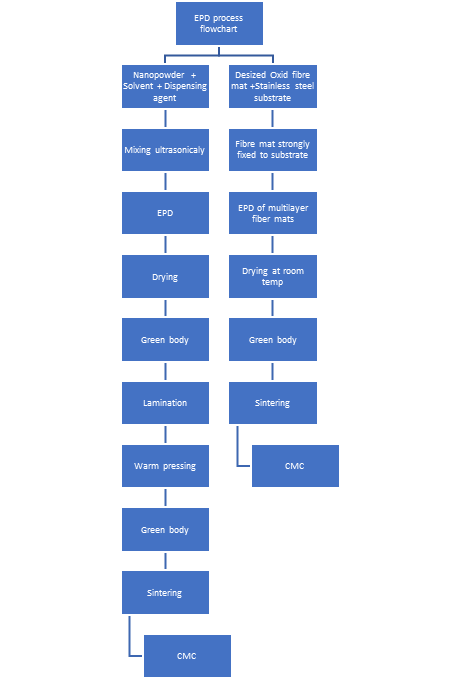
Figure 1. EPD process flowchart.
2. Matrix Deposition/Infiltration from a Gas Phase
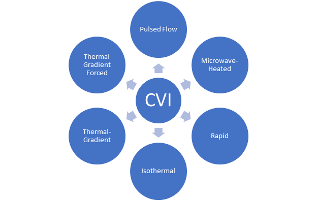
Figure 2. Chemical Vapor Deposition processing techniques.
3. Melt Infiltration
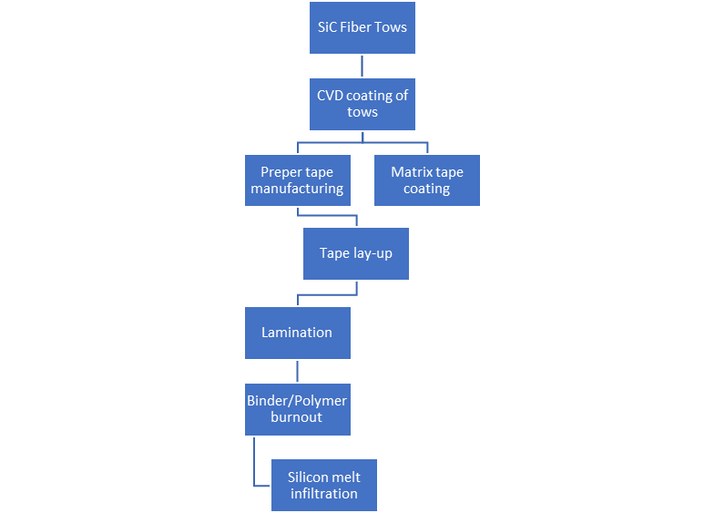
Furthermore, other researchers have developed a multi-physics fully integrated computational model by using the MI process. A porous CMC preform was mixed with an unsaturated fluid flow, to create a porous matrix with a molten silicon infiltrant. This resulted in a mechanical and thermal properties estimation comparison with previous literature for the manufacturing of CMC microstructures with the MI process, allowing for high strength and good oxidation and corrosion resistance.
4. Matrix Forming via Pyrolysis of C- & Si-Containing Polymers
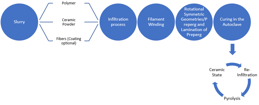
Figure 4. Polymer Infiltration process steps.
5. Matrix Forming via Sol-Gel
6. Matrix Forming via Sintering
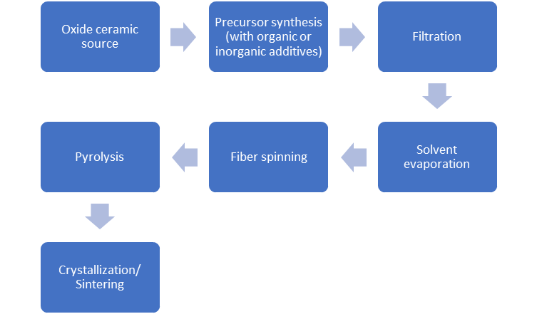
Figure 5. Sintering of an oxide precursor (Al2O3) mixed with oxide filler (fiber) flowchart.
Figure 5 shows a flow diagram of the chemical processing of ceramic oxide fibers, where an oxide ceramic precursor is mixed with inorganic additives (silica precursor, etc.), allowing the preparation of a viscous liquid used for fiber spinning. Then the fiber is processed as a dilute solution to be filtered and avoid particulate contamination. When filtering is finished, the precursor is added in a vacuum to remove any solvent and spin dope. In continuous dry spinning is used by using water as a spin dope solvent, this vaporated while spinning, producing a rigid fiber. The filaments are pyrolyzed at 300oC to 500oC, to clear volatile components of the precursor, leading to ceramic fibers. If the temperature surpasses 800oC, crystallization of the fiber into the alumina occurs.
7. Matrix Forming via Chemical Reaction
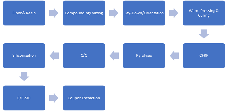
Figure 6. Liquid Silicon Infiltration Process Flowchart.
8. Selecting the Most Appropriate Manufacturing System
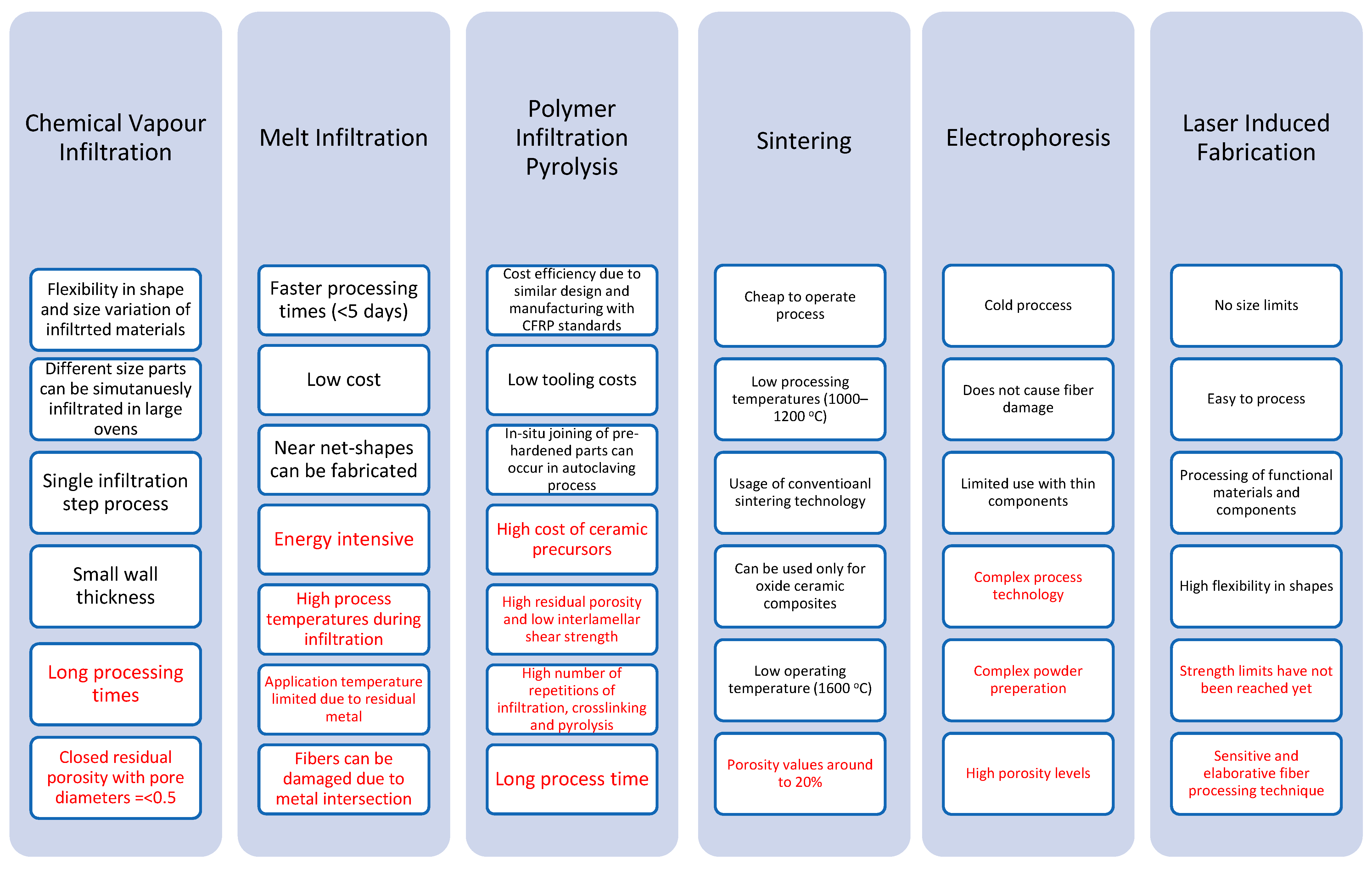
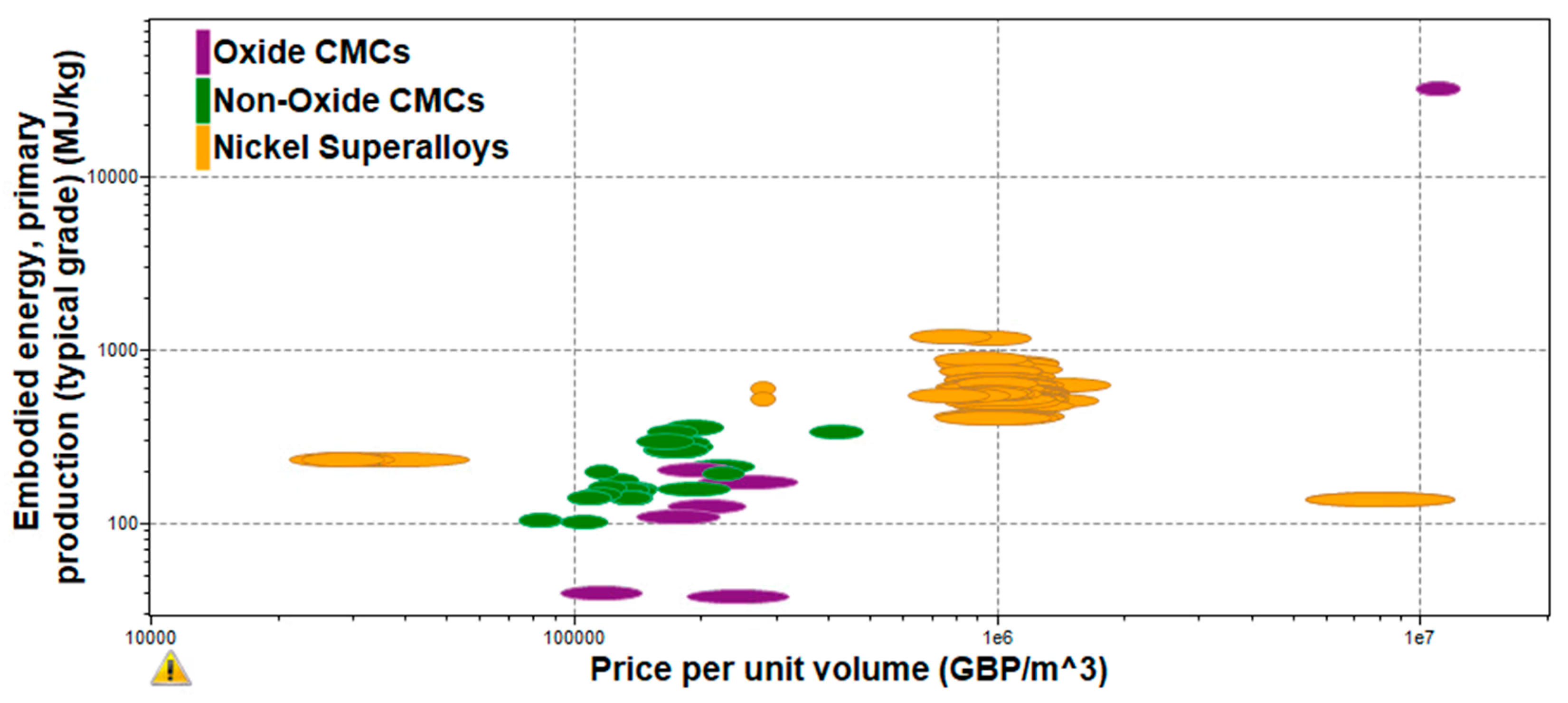
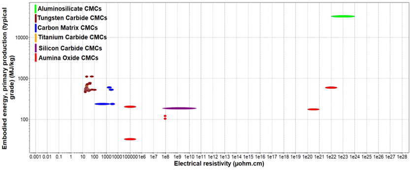
Figure 9. Embodies Energy vs Electrical Resistivity of CMCs.
Figure 10 shows the embodied energy and the electrical resistivity of different ceramic matrix composite categories. As it can be observed from the figure above, aluminosilicate CMCs have the highest embodied energy and electrical resistivity values as they have some of the more complex material compositions. This indicates that the manufacturing process used to compose this CMC (sol-gel infiltration, sintering) requires a lot of energy and time, increasing the final cost of the production of aluminosilicate-based applications. On the other hand, carbon matrix, alumina oxide, and silicon carbide CMCs have lower embodied energy and electrical resistivity, meaning that these materials are easier to be produced at larger production rates with lower overall costs and faster time scales. This is because their process materials have less complex compositions as they include smaller amounts of fibers and matrix materials.
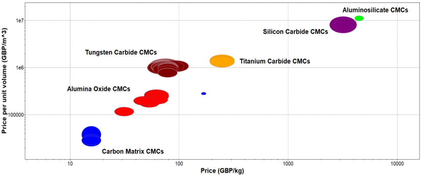
Figure 10. Price Per Unit Volume vs Price of CMCs.
The material comparison in Figure 9 justifies the material comparison in Figure 10 where aluminosilicates are the most expensive composites to produce from both oxide and non-oxide CMCs. On the other hand, alumina oxide composites are much more cost-effective to produce from the oxide CMCs allowing a wider range of materials submerged into the final matrix without having an excessive price increase in manufacturing processes. Finally, carbon matrix CMCs have the lowest production and manufacturing cost as they use the least amount of embodied energy and electrical resistivity and they are also cost-effective to extract and purchase. Although some of the manufacturing techniques used for the production of these materials are not the most cost-efficient and time-consuming such as PIP, MI, and CVI processes.
This entry is adapted from the peer-reviewed paper 10.3390/app13053017
References
- Simon, R. Progress in Processing and Performance of Porous-Matrix Oxide/Oxide Composites. Int. J. App. Cer. Tech. 2005, 2, 141–149.
- Bao, Y.; Nicholson, P.S. Constant Current Electrophoretic Infiltration Deposition of Fiber-Reinforced Ceramic Composites. J. Am. Ceram. Soc. 2007, 90, 1063–1070.
- Boccaccini, A.R.; Kaya, C.; Chawla, K.K. Use of electrophoretic deposition in the processing of fiber-reinforced ceramic and glass matrix composites: A review. Compos. A 2001, 32, 997–1006.
- Boccaccini, A.R.; Kaya, C. The use of electrophoretic deposition for the fabrication of ceramic and glass matrix composites. Ceram. Trans. 2004, 153, 57–66.
- Ziegler, G.; Richter, I.D.; Suttor, D. Fiber-reinforced composites with polymer-derived matrix: Processing, matrix formation, and properties. Comp. Part A App. Sci. Man. 1999, 30, 411–417.
- Ordnung, M.; Lehmann, J.; Ziegler, G. Electrophoretic deposition of silicon powder for the production of fiber-reinforced ceramic matrix composites. In Electrophoretic Deposition, Fundamentals and Applications; The Electrochemical Society: Honolulu, HI, USA, 2002; pp. 255–263. Available online: https://books.google.co.uk/books?hl=en&lr=&id=wkWj4njEJl8C&oi=fnd&pg=PA255&dq=+electrophoretic+deposition+of+silicon+powder&ots=sRYb6d3QK-&sig=Z91jmL-xZaU9AXREAq3TO8z5-ks#v=onepage&q=electrophoretic%20deposition%20of%20silicon%20powder&f=false (accessed on 21 February 2023).
- Kooner, S.; Westby, W.S.; Watson, C.M.A.; Farries, P.M. Processing of Nextel 720/mullite composition. composite using electrophoretic deposition. J. Eur. Ceram. Soc. 2000, 20, 631–638.
- Manocha, L.M.; Panchal, C.; Manocha, S. Silica/silica composites through electrophoretic infiltration. Effect of processing conditions on densification of composites. Sci. Eng. Comp. Mater. 2000, 9, 219–230.
- Kaya, C.; Kaya, F.; Boccaccini, A.R. Electrophoretic de-position infiltration of 2-D metal fiber-reinforced cordierite matrix composites of tubular shape. J. Mater. Sci. 2002, 37, 4145–4153.
- Kaya, C.; Kaya, F.; Atiq, S.; Boccaccini, A.R. Electrophoretic deposition of ceramic coatings on ceramic composite substrates. Br. Ceram. Trans. 2003, 102, 99–102.
- Novak, S.; König, K.; Iveković, A. Electrophoretic Deposition in Production of Ceramic Matrix Composites. In Electrophoretic Deposition of Nanomaterials. Nanostructure Science and Technology; Dickerson, J., Boccaccini, A., Eds.; Springer: New York, NY, USA, 2012.
- Corni, I.; Ryan, M.P.; Boccaccini, A.R. Electrophoretic deposition: From traditional ceramics to nanotechnology. J. Eur. Ceram. Soc. 2008, 28, 1353–1367.
- Vignoles, G.L. Modeling of chemical vapor infiltration processes. Adv. Compos. Manuf. Process Des. 2015, 17, 415–458.
- Lamon, J. Chemical Vapor Infiltrated SiC/SiC Composites (CVI/SiC/SiC). In Handbook of Ceramic Composites; Springer: New York, NY, USA, 2005; pp. 55–76.
- Probst, K.J.; Besmann, T.M.; Stinton, D.P.; Lowden, R.A.; Anderson, T.J.; Starr, T.L. Recent advances in forced-flow, thermal-gradient CVI for refractory composites. Surf. Coat. Technol. 1999, 120, 250–258.
- Timofeev, P.A.; Timofeev, I.A.; Bogachev, E.A.; Timofeev, A.N. Modern approaches to the manufacture of ceramic matrix composite materials for long-term operation at temperatures above 1000 °C. Review of world experience and capabilities of JSC “Kompozit”. IOP Conf. Ser. Mater. Sci. Eng. 2019, 683, 012038.
- Lazzeri, A. CVI Processing of Ceramic Composites. In Ceramic and Composites Processing Methods; Wiley: New York, NY, USA, 2012; pp. 313–349.
- Naslain, R.R.; Langlais, F. CVD—Processing of ceramic—Ceramic composite materials. In Materials Science Research: Tailoring Multiphase and Composite Ceramics; Springer: Heidelberg, Germany, 1986; Volume 20, pp. 145–164.
- Weiss, R. Carbon/carbons and their industrial applications. In Ceramic Matrix Composites, Fiber Reinforced Ceramics and Their Applications; Krenkel, W., Ed.; Wiley-VCH Verlag GmbH & Co.: Weinheim, Germany, 2006; pp. 69–112.
- Besmann, T.M.; McLaughlin, J.C.; Lin, H.T. Fabrication of ceramic composites—Forced CVI. J. Nucl. Mater. 1995, 219, 31–35.
- Lackey, W.; Starr, T. Fabrication of fiber-reinforced ceramic composites by chemical vapor infiltration: Processing, structure, and properties. In Proceedings of the 8th Annual Conference on Composites and Advanced Ceramic Materials: Ceramic Engineering and Science Proceedings, Cocoa Beach, FL, USA, 15–18 January 1984; John Wiley & Sons, Inc.: Hoboken, NJ, USA, 1990; pp. 397–445.
- Yin, Y.; Binner, J.; Cross, T. Cross Microwave-assisted chemical vapor infiltration for ceramic matrix composites. Ceram. Trans. 1997, 80, 349–356.
- Binner, J.; Vaidhyanathan, B. When should microwaves be used to process technical ceramics? In Materials Science Forum; Trans Tech Publications, Ltd.: Stafa-Zurich, Switzerland, 2009; Volume 606, pp. 51–59.
- Cioni, B.; Lazzeri, A. Modeling and development of a microwave-assisted pilot plant for the production of SiC-based matrix composites. Int. J. Chem. React. Eng. 2008, 6, 1–23.
- Timms, L.A.; Westby, W.; Prentice, C.; Jaglin, D.; Shatwell, R.A.; Binner, J.G.P. Reducing chemical vapor infiltration time for ceramic matrix composites. J. Microsc. 2001, 201, 316–323.
- Wang, J.P.; Qian, J.M.; Qiao, G.J.; Jin, Z.H. Improvement of film boiling chemical vapor infiltration process for fabrication of large size C/C composite. Mater. Lett. 2006, 60, 1269–1272.
- Kutemeyer, M.; Schomer, L. Fabrication of ultra high temperature ceramic matrix composites using a reactive melt infiltration process. J. Eur. Ceram. Soc. 2016, 36, 3647–3655.
- Naslain, R.R. Ceramic Matrix Composites: Matrices and Processing. In Encyclopedia of Materials: Science and Technology, 2nd ed.; Elsevier: Amsterdam, The Netherlands, 2001; pp. 1060–1066.
- Zoli, L.; Sciti, D. Efficacy of a ZrB2-SiC matrix in protecting C fibers from oxidation in novel UHTCMC materials. Mater. Des. 2016, 113, 207–213.
- Yin, X.; He, S.; Zhang, L.; Fan, S.; Cheng, L.; Tian, G.; Li, T. Fabrication and characterization of a carbon fibre reinforced carbon-silicon carbide-titanium silicon carbide hybrid matrix composite. Mater. Sci. Eng. A 2010, 527, 835–841.
- Kopeliovich, D. Advances in the manufacture of ceramic matrix composites using infiltration techniques. Adv. Ceram. Matrix Compos. 2014, 5, 79–108.
- Mingazzini, C.; Brentari, A.; Burgio, F.; Burresi, E.; Scafè, M.; Pilloni, L.; Caretti, D.; Nanni, D. Optimization of a pyrolysis procedure for obtaining SiC-SiCf CMC by PIP for term structural applications. In Advances in Science and Technology; Trans Tech Publications Ltd.: Stafa-Zurich, Switzerland, 2013; Volume 77, pp. 153–158.
- Kopeliovich, K. Fabrication of Ceramic Matrix Composites by Polymer Infiltration and Pyrolysis (PIP). 2012. Available online: https://www.substech.com/dokuwiki/doku.php?id=fabrication_of_ceramic_matrix_composites_by_polymer_infiltration_and_pyrolysis_pip (accessed on 23 December 2022).
- Francis, A. Progress in polymer-derived functional silicon-based ceramic composites for biomedical and engineering applications. Mater. Res. Express 2018, 5, 062003.
- Singh, D.; Singh, J.P. The effect of Processing in Strength of Nicalon Fibers in Nicalon Fiber-SiC Matrix Composites. In Proceedings of the 16th Annual Conference on Composites and Advanced Ceramic Materials: Ceramic Engineering and Science Proceedings, Cocoa Beach, FL, USA, 7–10 January 1992; John Wiley & Sons, Inc.: Hoboken, NJ, USA, 1992.
- Dey, A.; Chatterjee, M.; Naskar, M.K.; Basu, K. Near-net-shape fiber-reinforced ceramic matrix composites by the sol infiltration technique. Mater. Lett. 2003, 57, 2919–2926.
- Naskar, M.K.; Chatterjee, M.; Dey, A.; Basu, K. Effects of processing parameters on the fabrication of near-net-shape fiber-reinforced oxide ceramic matrix composites via sol-gel route. Ceram. Int. 2004, 30, 257–265.
- Young, S.K. Sol-Gel Science for Ceramic Materials. Mater. Matters 2006, 13, 8.
- Nazeri, A.; Bescher, E.; Mackenzie, J.D. Ceramic Composites by the Sol-Gel Method: A Review. In Ceramic Engineering and Science Proceedings; John Wiley & Sons: Hoboken, NJ, USA, 2008; Volume 14, pp. 1–19.
- Saruhan, B. Fabrication of Oxide-Matrix Composites. In Oxide-Based Fiber-Reinforced Ceramic-Matrix Composites; Springer: New York, NY, USA, 2003.
- Molinari, A. Fundamentals of Sintering: Solid State Sintering. In Encyclopedia of Materials: Metals and Alloys; Elsevier: Amsterdam, The Netherlands, 2022; Volume 3, pp. 471–480.
- Liu, P.S.; Chen, G.F. Making Porous Metals: Processing and Applications; Elsevier: Amsterdam, The Netherlands, 2014; pp. 21–112.
- Wei, Z.Y.; Meng, G.H.; Chen, L.; Li, G.R.; Liu, M.J.; Zhang, W.X.; Zhao, L.N.; Zhang, Q.; Zhang, X.D.; Wan, C.L.; et al. Progress in ceramic materials and structure design toward advanced thermal barrier coatings. J. Adv. Ceram. 2022, 11, 985–1068.
- Laszkiewicz, L.J. Spark Plasma Sintering/Field Assisted Sintering Technique as a Universal Method for the Synthesis, Densification and Bonding Processes for Metal, Ceramic and Composite Material. J. Appl. Mater. Eng. 2021, 60, 53–69.
- Kochendörfer, R.; Lützenburger, N. Applications of CMCs Made via the Liquid Silicon Infiltration (LSI) Technique High-Temperature. In High Temperature Ceramic Matrix Composites; Wiley-VCH Verlag GmbH: Weinheim, Germany, 2001; pp. 277–287.
- Margiotta, J.C.; Zhang, D.; Nagle, D.C. A Microstructural evolution during silicon carbide (SiC) formation by liquid silicon infiltration using optical microscopy. Int. J. Refract. Met. Hard Mater. 2010, 28, 191–197.
- Schulte-Fischedick, J.; Seiz, S.; Lützenburger, N.; Wanner, A.; Voggenreiter, H. The crack development on the micro- and mesoscopic scale during the pyrolysis of carbon fibre reinforced plastics to carbon/carbon composites. Compos. Part A-Appl. Sci. Manuf. 2007, 39, 2171–2181.
- Axinte, A.; Ungureanu, D.; Țăranu, N.; Bejan, L.; Isopescu, D.N.; Lupășteanu, R.; Hudișteanu, I.; Roșca, V.E. Influence of Woven-Fabric Type on the Efficiency of Fabric-Reinforced Polymer Composites. Materials 2022, 15, 3165.
- Zivic, F.; Palic, N.; Jovanović, Ž.; Grujovic, N. Processing Routes for Ceramic Matrix Composites (CMCs). In Encyclopedia of Materials: Composites; Elsevier: Amsterdam, The Netherlands, 2021; pp. 20–36.
