Your browser does not fully support modern features. Please upgrade for a smoother experience.
Please note this is an old version of this entry, which may differ significantly from the current revision.
With the rapid development of the electric vehicle (EV) industry, charging facilities for electric vehicles are gradually improving, thus meeting the demand for fast and safe charging.
- electric vehicle
- fast-charging system
- AC/DC converter
1. Charging Level of Electric Vehicles
Electric vehicle (EV) charging systems can be divided into slow- and fast-charging systems. Slow-charging systems are generally defined as Level 1 and Level 2 on-board charging systems. Level 1 on-board charging systems are slow and take about 8–10 h to fully charge a power battery. They are primarily used in residential buildings and the output power is usually less than 10 kW. In contrast, Level 2 charging systems take less time than Level 1 systems to fully charge a battery. They are usually used in shopping malls, public facilities, etc., and the power can reach 20 kW [1].
Currently, there are two general topologies for slow-charging systems, namely on-board charging systems. One is a single-stage topology with an uncontrolled rectifier and high-frequency DC/DC converter. This topology includes forward, flyback, push-pull, half-bridge, and full-bridge. Single-stage topology has the advantages of a simple structure, smaller number of components, small size, etc., but because it is directly connected to the grid, it can easily pollute the grid. The other is a two-stage charging system with power factor correction in the front stage and a DC/DC converter in the rear stage. The two-stage charging system can effectively address the issues of the low power factor and serious harmonic pollution but it has a high cost and low efficiency. Currently, the conventional PID control method is widely used for slow-charging systems but more advanced control methods, such as BP neural network PID control methods and fuzzy adaptive PID control methods, have also been developed, which can significantly affect the charging output characteristics.
As the number of EVs in use has increased, so has consumer demand for faster charging systems, as slow-charging systems have a long charging time and low power output. Fast-charging systems are a type of non-vehicle charging system that can be classified into fast and ultra-fast types.
Table 1 shows the types and levels of EV charging, and Table 2 summarizes the current advanced fast/ultra-fast-charging systems with hundred-kilowatt power levels.
Table 1. Electric vehicle charging types and levels.
| Charging Type | Charging Location | Specifications | Charging Time (Battery Capacity) |
Criterion | ||
|---|---|---|---|---|---|---|
| Voltage/V | Current/A | Power/kW | ||||
| Level 1 | On-board | 120/230 | 12–16 | 1.44–1.92 | 11–36 h (16–50 kWh) |
International Electrotechnical Commission (IEC) |
| Level 2 | On-board | 208/240 | 15–80 | 3.1–19.2 | 2–6 h (16–30 kWh) |
|
| Level 3 (Fast) | Off-board | 300–600 | ≤400 | 50–350 | ≤30 min (20–50 kWh) |
|
| Ultra-fast | Off-board | >800 | >400 | ≥400 | ≈10 min (20–50 kWh) |
|
Table 2. Characteristics of the 100-kilowatt-class of fast/ultra-fast-charging systems.
| Manufacturer and Model | Power/kW | Input Voltage/V | Output Voltage/V | Output Current/A | Supported Standards | Peak Efficiency/% | Weight/Ibs |
|---|---|---|---|---|---|---|---|
| EVBox Troniq 100 | 100 | 480 Vac ± 10% | 500 | 200 | CCS Combo 1, CHAdeMO | 95 | 2535 |
| PHIHONG Integrated Type | 120 | 380/480 Vac ± 10% | 200–750 | 240 | GB/T 20234.3 | 93.5 | 528 |
| Tesla Supercharger | 135 | 380–480 Vac | 50–410 | 330 | Super charger |
91 | 1323 |
| EVTEC espresso and charger | 150 | 400 Vac ± 10% | 170–940 | 50–400 | SAE Combo 1, CHAdeMO | 93 | 881 |
| Delta | 200 | 400 Vac ± 10% | 200–1000 | 350–500 | CHAdeMO, CCS | 94 | 992 |
| ABB Terra HP | 350 | 400 Vac ± 10% | 150–920 | 500 | SAE Combo 1, CHAdeMO 1.2 | 95 | 2954 |
| Tritium Veefil PK | 475 | 480 Vac | 920 | 500 | CHAdeMO, CCS | 98.5 | 1540 |
2. Electric Vehicle Fast-Charging System Architecture
EV charging systems generally have a centralized layout in a specific area, and the power supply typically employs AC coupling or DC coupling, that is, multiple independent charging systems use the common AC bus or common DC bus to obtain power. The configuration is shown in Figure 1.
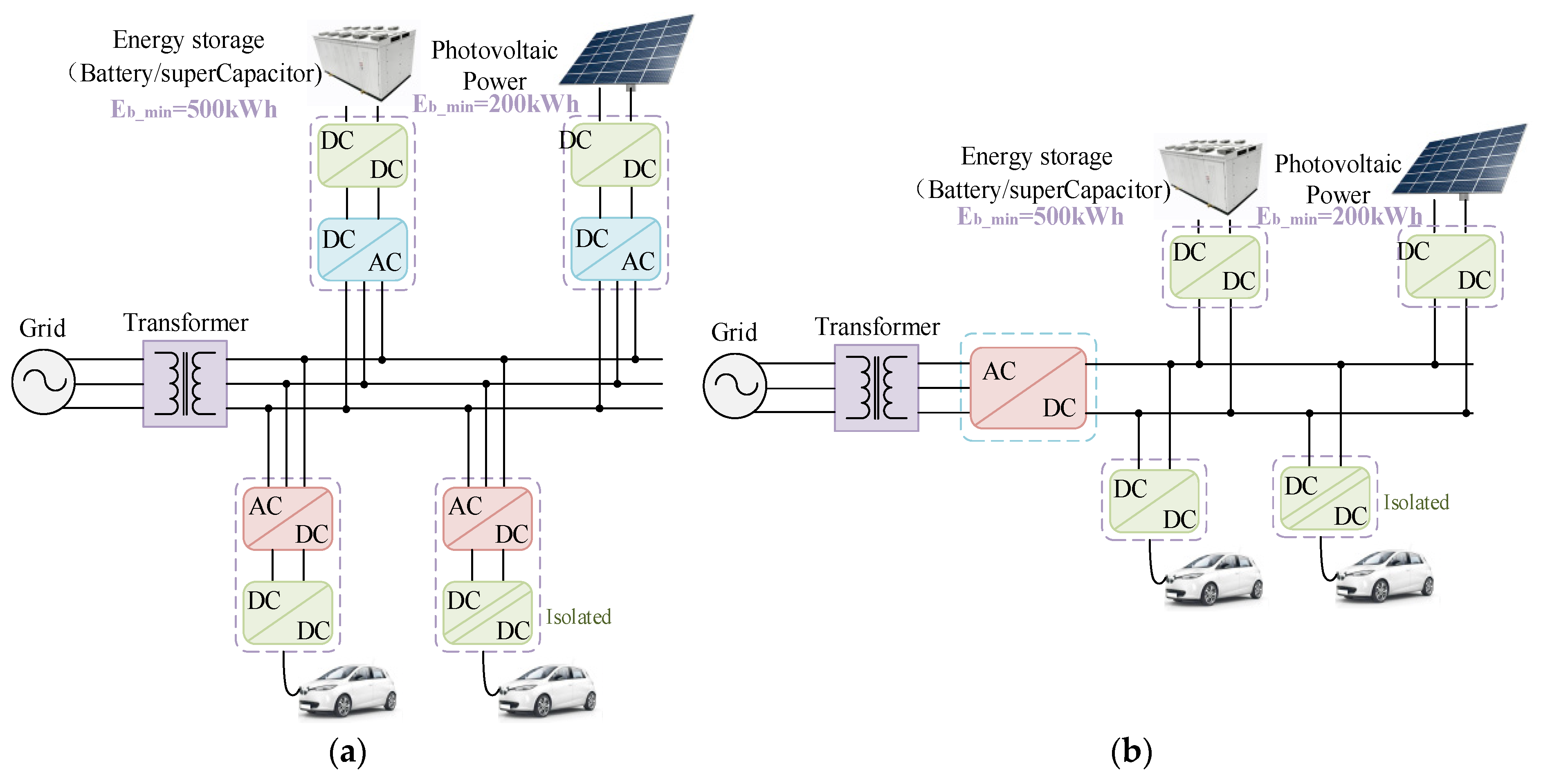
Figure 1. Electric vehicle fast-charging system architecture. (a) AC coupling configuration method. (b) DC coupling configuration method.
In the AC-coupled configuration, a low-frequency transformer is used to connect the medium-voltage grid to the common coupling point of the charging system to supply power to each independent charging system. Each charging system consists of an AC/DC converter and a DC/DC converter. Many charging systems use the AC coupling configuration because the converter technology is mature and the AC distribution system is stable. However, the overall complexity of system control is high since the power flow between the grid and the EV must pass through the AC bus and multiple AC/DC and DC/DC converters [2].
In the DC-coupled configuration, high-power AC/DC converters are connected to a low-frequency transformer, which is then coupled to the EV charging system through a DC bus. This configuration uses centralized rectification, which effectively reduces the number of AC/DC converters, simplifies system control, and alleviates the impact of high-power charging on the grid [3]. The DC bus power supply structure is used to effectively avoid the problems of the power angle, frequency stability, and reactive loop current in the AC bus. The power flow between the grid and the EV can be controlled by detecting the magnitudes of the AC and DC side voltages and currents on the grid side. However, the DC/DC converters connected to EVs typically have an isolation-type structure, which means that each charging system needs to be equipped with high-frequency transformers. However, the primary and secondary circuits of these high-frequency transformers still need to be controlled independently, which results in a high level of complexity in the control system of the charging station’s rear stage [4][5].
The fast-charging system consists of two AC/DC conversion stages: the first is the rectification stage that converts three-phase AC power to high-voltage DC power, i.e., AC/DC, which includes power factor correction (PFC) to improve power utilization effectively. The second stage is the conversion of high-voltage DC power to DC power that matches the voltage level of the load, i.e., DC/DC. Typically, an EV charging strategy involves the battery constant current (CC) and constant voltage (CV) charging, which are performed by DC/DC converters [6]. A block diagram of the fast-charging system configuration is shown in Figure 2. The control algorithms used for the charging mode operation of the power control unit include proportional–integral (PI) control, proportional–integral–derivative (PID) control, sliding-mode control, and neural network control [7].
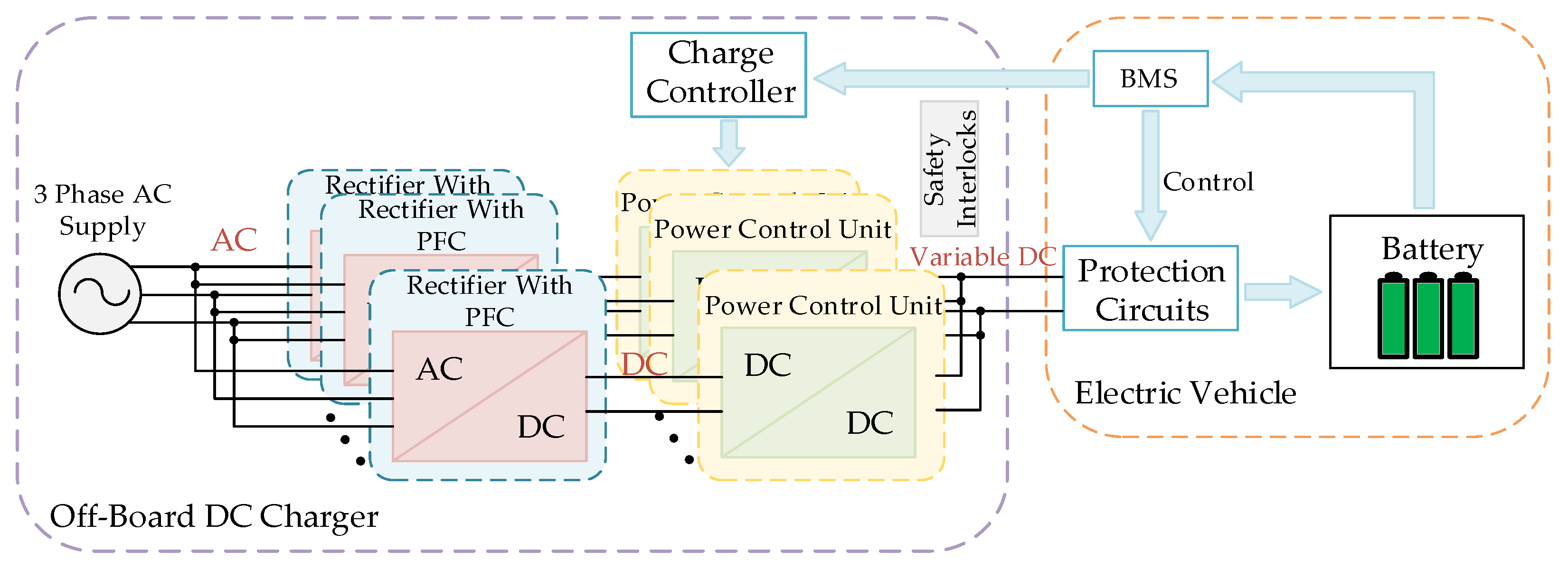
Figure 2. Block diagram of the configuration of the fast-charging system.
According to IEEE Standard 1547 [8], electrical isolation between the grid and the EV power cell can be provided by a low-frequency transformer or a high-frequency transformer inside the isolated DC/DC converter. The electrical isolation allows the power modules to be connected in parallel. If a single module cannot meet the power requirements of a fast-charging system, connecting multiple identical modules in parallel can increase the output power.
This entry is adapted from the peer-reviewed paper 10.3390/electronics12071581
References
- SAE International. Electric Vehicle and Plug in Hybrid Electric Vehicle Conductive Charge Coupler; SAE International: Warrendale, PA, USA, 2017.
- Srdic, S.; Lukic, S. Toward Extreme Fast Charging: Challenges and Opportunities in Directly Connecting to Medium-Voltage Line. IEEE Electr. Mag. 2019, 7, 22–31.
- Purgat, P.; van der Blij, N.H.; Qin, Z.; Bauer, P. Partially Rated Power Flow Control Converter Modeling for Low-Voltage DC Grids. IEEE J. Emerg. Sel. Top. Power Electron. 2020, 8, 2430–2444.
- Sharma, G.; Sood, V.K.; Alam, M.S.; Shariff, S.M. Comparison of Common DC and AC Bus Architectures for EV Fast Charging Stations and Impact on Power Quality. eTransportation 2020, 5, 100066.
- Ronanki, D.; Kelkar, A.; Williamson, S.S. Extreme Fast Charging Technology-Prospects to Enhance Sustainable Electric Transportation. Energies 2019, 12, 3721.
- Safayatullah, M.; Elrais, M.T.; Ghosh, S.; Rezaii, Z.; Batarseh, I. A Comprehensive Review of Power Converter Topologies and Control Methods for Electric Vehicle Fast Charging Applications. IEEE Access 2022, 10, 40753–40793.
- Yilmaz, M.; Krein, P.T. Review of Battery Charger Topologies, Charging Power Levels, and Infrastructure for Plug-In Electric and Hybrid Vehicles. IEEE Trans. Power Electron. 2013, 28, 2151–2169.
- IEEE Application Guide for IEEE Std 1547TM; IEEE Standard for Interconnecting Distributed Resources with Electric Power Systems. IEEE: New York, NY, USA, 2009.
This entry is offline, you can click here to edit this entry!