Your browser does not fully support modern features. Please upgrade for a smoother experience.
Please note this is an old version of this entry, which may differ significantly from the current revision.
Subjects:
Engineering, Electrical & Electronic
In 1961, a theory relating to ionic wind was developed by Robinson, who proposed the possibility of developing functional electrostatic blowers, namely electrohydrodynamic (EHD) gas pumps.
- functional fluidic pumps
- electrohydrodynamic pumps
- flow delivery
- robotics
1. Brief History of the EHD Pump
EHD effects were first discovered in 1629 by Cabeo, who observed that electric fields could attract sawdust, after noticing repulsion following physical contact [1]. However, Cabeo did not understand the rationale behind this phenomenon. Over the next few hundred years, Wilson investigated the EHD effect, coining the term electric wind, and attempted to find practical applications [2]. In 1961, a theory relating to ionic wind was developed by Robinson, who proposed the possibility of developing functional electrostatic blowers, namely EHD gas pumps [3]. Although this electrostatic blower had the advantages of low wear, quiet operation, and no requirement for lubrication as compared to conventional fans (i.e., a mechanical pump), Robinson was disappointed by the inability to overcome the extremely low operating efficiency (the conversion efficiency was less than 1% from corona discharge to mechanical energy). The low conversion efficiency from electrical to mechanical energy represented a primary limitation of EHD pumps. Many researchers attempted to improve the device structure using EHD pumps, and there have been some experimental studies focused on improving the flow rate and efficiency of EHD pumps. In 2008, Moreau et al. made substantial improvements [4]. Morrow et al. increased the electrical energy conversion efficiency to 1.72% via the pin-ring and pin-grid electrode configuration, which provided more than twice the conversion efficiency compared to previous EHD effect studies. In recent times, the higher energy conversion efficiency of EHD pumps has also been demonstrated by June et al. [5]. June et al. experimentally tested a five-needle mesh-like EHD pump prototype and found static efficiencies of up to 14%.
In addition to EHD air pumps, functional fluidic EHD pumps have also been developed in recent decades. Sharbaugh et al. [6] were the first to use media other than air in EHD pumps, attempting to apply EHD pumps to transformers. However, this was deemed impractical owing to subsequent contamination of the collector electrode after hundreds of hours of operation. Five-years later, Crowley et al. were the first researchers to publish an experimental study on the behavior of multiple working fluids using a rectangular EHD pump with a parallel strip-to-strip electrode [7]. This paper develops a basic EHD pumping model to illustrate the working fluid’s material properties. They applied the model to several experimental pumps reported earlier and found good agreement. Examples of this model demonstrate several new fluids suitable for EHD pumping. The authors concluded that there are considerable differences in the maximum velocity that can be achieved for different fluids and that the maximum velocity for a given fluid cannot determine the maximum efficiency. The basic geometry of a functional fluidic EHD pump is depicted in Figure 1. Several years later, a multi-stage EHD pump using transformer oil as the working fluid was designed as a practical solution for motor cooling [8,9]. There are also studies using a dielectric fluid (dibutyl sebacate, an organic plasticizer) as a medium, both as a single-stage and a multi-stage configuration of the same geometry. Researchers in other studies also employed a dielectric fluid (such as dibutyl sebacate) as a medium, both as single- and multi-stage configurations of the same geometry [10,11].
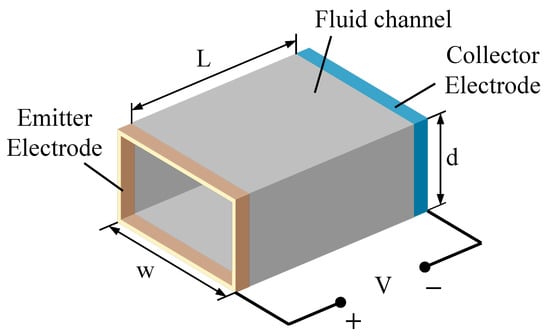
Figure 1. Fluid EHD pump geometry [7]. L, d and w represent channel length, depth and width, respectively. V denotes the high-voltage power source.
Despite the computational conditions, the flawed theories of physics and materials science, and the limitations of experimental equipment, previous explorations built the foundation for future research, as these results retain the majority of their validity even today.
2. Pump Structure and Material
This section introduces the EHD functional fluidic and gas pump’s base, electrode material, and geometry selection.
Currently, there are many EHD pump electrode geometries, such as needle, ring, planar, wire, mesh, and disk. These electrodes can form five basic electrode pairs in functional fluidic EHD pumps: thin planar electrode pairs, needle-to-ring electrode pairs, disk electrode pairs, triangular prism-to-silt electrodes (TPSE), and helical electrodes. Schematics of some electrode pairs are shown in Figure 4. Thin planar electrode pairs bear a low power density of 6.3 Wm/cm22[48] while needle-to-ring electrode pairs and TPSE are 111 Wm/cm22[49] and 17.5 Wm/cm22 [50]. Thin planar electrodes and TPSE generally use photomask patterning, which is easy to reproduce; however, needle ring electrodes are mainly assembled manually, with low reproducibility [51]. Moreover, thin planar electrodes and TPSE are fabricated with batches and are easy to integrate. However, needle ring electrodes are individually manufactured and hard to integrate.
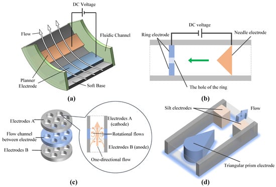
Different electrode shapes can affect conduction-pumping properties such as static pressure, flow rate and efficiency [55]. The flow and pressure of an EHD pump increase as the applied voltage increases. The consumption of the pump is on the order of mW. The flow and pressure of the EHD functional fluidic pump depend on the pattern of the electrodes. Compared with needle ring and thin planar electrodes, triangular prism and silt electrode pair electrode patterns are widely used due to their high-output power density, and high compatibility with Micro-Electro-Mechanical System processes [39]. The electrode material can also affect the performance of the pump. For example, using parallel planar electrodes and HFE-7100 as the working fluid, the same design using copper electrodes requires more than twice the voltage to produce the same performance [56].
The base material of EHD pump can be hard or soft. Hard material includes silicon and glass [57]. Soft material includes PTFE, PET and PP. Rigid EHD pumps installed with rigid bases are used to drive the actuators, while soft EHD pumps loaded with flexible bases power the actuators and the soft parts of the bodies [58]. EHD pumps with flexible bases can achieve states such as bending and twisting.
Electrode materials such as aluminum, copper, titanium, and steel are commonly corroded by corona [69,70]. Noll et al. performed ionization tests using germanium and silicon needles to overcome corrosion effects [71]. Sometimes, it is also possible to apply a corrosion-resistant material to the electrode surface [72].
EHD gas pumps mainly use electrode pairs such as wire-(rod/ring/plate/mesh), mesh-(rod/ring), and needle-(plate/ring). Figure 5 shows several representative electrode pairs. Moreover, most studies choose acrylic and glass as the material for the discharge chamber.
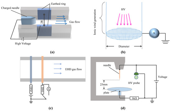
Electrode polarity, number of electrodes, and orientation of electrodes affect the flow of working gas in an EHD pump. Zhang and Lai [76] tried configuring 28 emitter electrodes in a square channel. After increasing the number of emitter electrodes, the electric field tends to become more uniform; however, there is also a limit to the volume flow that an EHD gas pump can produce. After adding the secondary emitter electrode, as reported by Chang et al. [77], the secondary electrode can effectively increase the volume flow generated by the single primary electrode. However, its performance depends on the number of secondary electrodes added and the gap distance between primary and secondary electrodes. Another way to increase the volume flow rate is to use new electrode configurations, such as needle array-to-mesh [78,79] and wire array-to-mesh [27]. While these new electrode configurations generally result in higher volumetric flow rates, maintenance may become burdensome with application. Moreover, multi-stage EHD pumps [80,81] are more efficient than simply increasing the applied voltage of a single-stage pump if the flow distance is expected to be extended [82]. Investigations connecting multiple corona wind turbines in series to extend the EHD-induced flow over longer distances, confirmed that additional stages could increase the volumetric flow produced by a single individual stage [83].
This entry is adapted from the peer-reviewed paper 10.3390/mi14020321
This entry is offline, you can click here to edit this entry!