Methanol as a Clean Energy Carrier: History
Please note this is an old version of this entry, which may differ significantly from the current revision.

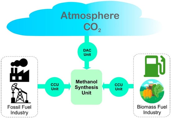
Clean methanol can play an important role in achieving net zero emission targets by decarbonizing the energy and chemical sectors. Conventionally, methanol is produced by using fossil fuel as raw material, which releases a significant amount of greenhouse gases (GHGs) into the environment. Clean methanol, which is produced by hydrogen (H2) from renewable sources (green H2) and captured carbon dioxide (CO2), is totally free from the influence of fossil fuel. Due to its vast applications, clean methanol has potential to substitute for fossil fuels while preventing further GHGs emissions. Renewable energy sources such as solar, wind and biomass should be utilized for producing green H2, while CO2 captured from air, and more likely from point emission sources, can be recycled to produce clean methanol. After producing methanol from CO2 and H2, the removal of by-product water by distillation is a big challenge due its high energy consumption. An alternative approach for this methanol-water separation is membrane technology, which is an energy saving option. Water-selective zeolite membranes can separate water post-synthesis, as well as during the synthesis. Production efficiency of methanol can be enhanced by utilizing zeolite membranes inside the methanol synthesis reactor. Furthermore, CO2 conversion as well as methanol selectivity, purity and yield can also be increased significantly by selectively removing by-product water using a zeolite membrane reactor.

  • methanol
  • carbon dioxide
  • hydrogenation
  • zeolite
  • membrane reactor

1. Feasibility of Methanol as Clean Source of Energy

Methanol is a simple C1 organic compound with many salient applications, such as vehicle fuel, marine fleet fuel, electricity generator fuel, fuel for direct methanol fuel cells and clean H2 production. Methanol also serves as starting material for several chemicals such as dimethyl ether (DME), formaldehyde, methylamine and acetic acid [38]. Methanol is produced globally, with its current volume of over 160 million metric tons [39] originating from fossil fuel-based raw materials such as coal, oil and natural gas. These fossil fuels undergo reforming processes to produce syngas, which is then converted to methanol via heterogeneous catalysis [40]. However, this method of methanol production is non-renewable, as it suffers from depletion of resources and also continuously pollutes the environment by emitting GHGs. Consequently, a lot of research interest worldwide has focused on sustainable clean methanol production routes having net zero GHGs emissions and low to zero impact on the environment [15,41].
Presently, clean methanol (also called e-methanol) is being produced from non-fossil-fuel resources, targeting production based on CO2 captured from CO2-rich sources and green H2 from water electrolysis using renewable resources [42,43]. The energy required for the water electrolysis process comes from renewable energy sources or from excess electricity from grid. Global environmental impact of methanol production from coal versus captured CO2 on all boundaries of an ecological system was assessed by Garay et al. [44]. They have shown that methanol production from captured CO2 and green H2 using renewable power source has far less of an impact on an ecosystem, compared to other technologies, providing a good “methanol economy” that closes the carbon loop to make a path towards carbon neutrality [45,46].
Carbon neutrality and clean methanol production are the fundamentals of green H2, which is considered valuable fuel, with an energy content of 142 MJ/kg [47], which is almost six times higher than that of methanol of 22.9 MJ/kg [48]. However, there are some disadvantages associated with it in terms of storage and handling. For example, direct physical storage of H2 fuel is much more expensive due to its high flammability and gaseous nature [49]. To store it in gaseous form requires high-pressure vessels up to 350–700 bars to ensure safety and limit the equipment’s footprint. On the other hand, liquid phase storage requires relatively small-sized equipment but subject to high volatility; the phase change temperature is −252.8 °C at atmospheric pressure and it requires cryogenic conditions for liquid phase storage [50]. An alternative to direct physical storage, H2 can be stored in the form of metal hydrides or chemical hydrides. Although metal hydrides provide an easier and safer storage medium for H2 at milder storage conditions, efficient materials with high number of H2 cycles should be used in order to reduce the solid waste generation [51]. Subsequently, chemical hydrides such as methanol could be used for H2 storage which also has wide range of applications in energy and chemical sectors. Therefore, methanol can serve as storage medium and carrier for clean renewable energy [38].
Methanol as fuel, energy storage medium and raw material has tremendous future industrial application; for example, it could be used by blending it with normal gasoline fuel in different ratios, commonly 15% methanol (M15) [52]. Another example: methanol-based biodiesel could be produced by trans-esterification of vegetable-oils to replace fossil fuels-based diesel in existing diesel engines [43,53]. Dimethyl ether (DME) is another important derivative of methanol which is produced from methanol via catalytic dehydration. Alternatively, DME could be applied to petroleum-based fuels due to its similar physical properties, to overcome fossil fuels challenges [54,55]. Additionally, methanol has the potential to energize industrial boilers, marine fleets, emergency electric generators and fuel cells for power generation [56,57].
Methanol is considered a promising medium for storing H2. To reproduce the stored H2, either methanol-water electrolysis [59,60,61], methanol-steam reforming (MSR) [62,63] or aqueous phase reforming (APR) [64,65] could be used. Methanol steam reforming is done over heterogeneous catalysts mainly based on Cu, Pd and Zn, and produces the H2 via following endothermic reaction [66],
CH3OH + H2O → CO2 + 3H2   ∆H298K° = +49.2 kJ/mol
In contrast to MSR, APR is performed at a lower temperature, and there is no need to evaporate the feed stock; hence, it is more energy efficient [67]. In the methanol-water electrolysis process, H2 is produced from an electrolyzer at the expense of external electricity. The voltage required for methanol-water electrolysis is about 0.03 V, which is far less than the voltage required for a simple water electrolysis of 1.23 V [68], whereby H2 production via methanol-water electrolysis consumes about 50% less power than pure water electrolysis [59,69]. This superior energy saving makes H2 production from methanol-water electrolysis more viable option than pure water electrolysis.
Direct methanol fuel cell (DMFC) converts the chemical energy of methanol into electricity and is used as sustainable power source for mobile devices [70,71] to produce electricity via the following electrochemical reactions [72]:
Anode reaction:
CH3OH + H2O → CO2 + 6H+ + 6e
Cathode reaction:
3/2O2 + 6H+ +6e → 3H2O
Overall redox reaction:
CH3OH + 3/2O2 → CO2 + 2H2O

2. Key Ingredients for Clean Methanol

Conventionally, methanol is produced from syngas (a mixture of CO2, CO and H2), which is primarily obtained from the reforming of fossil-fuel-based natural gas, coal or oil, while a major portion is obtained from natural gas. Methanol was first commercially produced from syngas in 1920s by Badische Anilin und Soda Fabrik (BASF) using very challenging conditions of 350–400 °C temperature and 240–300 bar pressure to compensate for the low activity of the catalyst used [74,75]. The major problem of using low temperature/pressure catalyst was in the impurities, such as sulfur from fossil fuel along with syngas, poisoning the catalysts. With the development of purification technologies, Imperial Chemical Industries (ICI) group successfully produced sulfur-free syngas. Subsequently, the researchers from this group produced methanol with Cu-based catalyst in much more favorable operating conditions of temperature and pressure of 200–300 °C and 30–54 bar, respectively [40].
The methanol synthesis using syngas route has a significant impact on the environment due to the direct usage of fossil fuels. In addition to the GHGs from the methanol consumption, a large amount of CO2 is also generated from the production plant itself. For instance, before feeding the syngas from the reformer section to the methanol production section, its CO2 content is required to be controlled by extracting the excess quantity of CO2. Without proper handling of the extracted CO2, this would result in an addition to net GHGs emissions [76].
With preference to utilize a greener approach, methanol should therefore be produced from clean and renewable raw materials while all energy utilities are obtained from clean resources. In other words, as an alternative to coal or natural gas, atmospheric CO2 and green H2 from water electrolysis are the integral components for production of clean methanol. In this scenario, catalytic hydrogenation of captured CO2 over Cu/ZnO-based catalyst can be a viable option to produce clean methanol.
The second component to produce clean methanol is CO2 where it is captured from atmosphere and industrial off-gases. The sources of atmospheric CO2 are mainly from industrial processes such as cement, fertilizers and steel manufacturing; it can be captured innovatively and subsequently directed to the methanol production plants. In some methanol utilization processes such as DMFC and methanol-water electrolysis or direct combustion, a significant amount of CO2 is released, which can also be recycled in order to close the carbon looping. Other renewable sources of CO2 and H2 may include biomass, natural organic feed stock and effluents from organic food processing industries; for example: vegetable oil when subjected to a gasification process [81,82,83].
In a nutshell, for sustainable production of clean methanol, there is a strong need of a sustainable supply of H2 for the decarbonization of the environment [84,85,86]. Following this strategy, several commercial facilities for producing clean methanol have emerged; for example, Liquid Wind, a Swedish company has committed to develop 10 methanol production facilities by 2030, each with a capacity of about 50,000 tons of e-methanol/year [87,88].

2.1. Production of Green Hydrogen

About 95% of global hydrogen (H2) is produced from fossil fuel sources, such as natural gas, coal and oil. The production of H2 has been classified into grey, blue and green H2, based on source and production strategy. Grey H2 is produced by steam reforming of fossil fuel and termed as “grey” due to substantial GHGs emissions during the process [89]. The source of blue H2 is also fossil fuel, but the production process must be equipped with efficient CO2 capturing facility (~100%) and have minimal GHGs impact on environment [90]. Green H2 is a totally environmentally-friendly process with zero GHGs emissions [91,92], produced by water electrolysis. The electrolyzer must be powered with renewable energy sources to avoid any GHG emission into the atmosphere during its entire production process [93]. This green H2 is the key approach towards achieving zero emission target of 2050 set by global climate communities. However, despite of the zero emissions from electrolysis operation, an electrolyzer manufacturing process could inevitably lead to GHG emissions, particularly if critical way materials are used, which should be taken into account for net zero emission target [94].

The PEMEL and AEL are low temperature electrolysis strategies to split water in acidic and alkaline media, respectively. In PEMEL, water is fed at the anode and oxidized to O2 at an iridium-based catalyst along with the release of protons and electrons, an oxygen evolution reaction (OER). The electrolysis cell contains a polymer electrolyte membrane (Nafion) having sulfonate functional groups to transport protons from anode to cathode. At cathode, a Pt-based catalyst assists protons to combine with electrons from an external field to generate H2 gas, a hydrogen evolution reaction (HER) [99]. PEMEL is operated at low temperature of between 20–80 °C and can generate ultrapure H2 and O2 from water splitting [98]. In spite of the ease of low temperate operation and product purity, the requirement of a noble metal catalyst raises the production cost. A noble metal catalyst is also necessary to withstand the corrosive acidic environment. To tackle this issue, Tajuddin et al. has recently developed non-noble based corrosion resistant electrodes for PEMEL applications. These electrodes can withstand the acidic environment of PEM electrolysis without any notable degradations [100]. Their study provides novel opportunities and new perspectives of replacing costly noble metals, particularly iridium, and can significantly reduce the production cost of H2.
In AEL, the electrolyte solution is composed of ~20 to 30% aqueous alkaline solution and the cell is operated at low temperatures of 30 to 80 °C [98]. The feed water is fed to the cathode where it is oxidized to H2 and generates OH ions. These hydroxyl ions pass through the alkaline media towards the anode to release electrons and produce oxygen. In an alkaline water electrolysis process, the problem of corrosive acidic media can be solved by providing alkaline water which can accept a broader range of non-noble metal-based electrocatalysts [97]. The problem associated with this AEL system is the sluggish reaction kinetics, and hence, a very high processing time which complicates its applicability on a large scale [101].

Solid oxide electrolysis (SOEL) is performed in a solid oxide electrolysis cell (SOEC) which works on the reverse principle of a solid oxide fuel cell, used for electricity production from pure H2 and O2 [102]. In SOEC, steam is fed at cathode and it undergoes reduction at high temperatures of 600–1000 °C to produce H2 and oxide ions [103]. Due to the high temperature, oxide ions can travel from cathode to anode via some oxide-conducting electrolyte medium, where it captures an electron from an outer circuit and generates oxygen gas. This process of H2 production has a good efficiency of more than 80% [102], however, it has the drawback of high-temperature operation [104]. To overcome this issue, researchers have made efforts to develop electrolytes for SOEC which can transfer ions at comparatively at low temperatures. Ishihara et al. performed steam electrolysis at 600 °C in SOEC having LaGaO3-based electrolytes and successfully achieved H2 production rate of 70 L/min at 1.8 V of applied potentia [105]. 

2.1.1. Solar to Hydrogen

Hydrogen (H2) production in water electrolyzer using solar electricity is a two-step process. Firstly, sunlight is converted to electricity using a photovoltaic (PV) cell which is then used in electrolyzer (EL) for water splitting. Alternatively, H2 can be produced from sunlight using photocatalysis (PC) and photo-electrocatalysis (PEC) [109] which is a direct water-splitting route from solar to H2 and thus avoids the energy losses by combining the two steps into a single one. Sunlight is directed onto the electrolysis solution containing photocatalyst or photo-electrocatalyst, which enables the water splitting reaction and thus produces H2 and oxygen (O2) without additional electricity [110,111].
In the PC method, the metal oxide-based semiconductors (photocatalyst) particles are dispersed in the aqueous electrolyte solution to generate electrons (e)

-holes (h+) pairs under sunlight irradiation. These e/h+ pairs migrate towards the active sites of respective electrodes to produce H2 and O2 [112,113,114]. In spite of direct exposure to sunlight in PC technology, the drawbacks include slow kinetics, unfavorable thermodynamics and some safety issues [115]. For instance, the separation of H2/O2 from the PC cell is needed to avoid H2 explosion in contrast with photovoltaic-electrocatalysis (PV-EC) and PEC [116]. Subsequently, research efforts have been focused to overcome these issues for better efficiency of converting solar energy to H2 by improving the semiconductor materials. For example, Wang et al. have developed Pt co-catalyzed BaTaO2N photocatalyst that produced 100 times more efficient H2 production compared to previous studies [117].

2.1.2. Wind to Hydrogen

Solar-driven hydrogen (H2) production is a growing technology for utilizing natural resources but lacks a consistent energy supply. To overcome this problem, wind energy is an alternative renewable source which can be integrated with the existing photovoltaic-electrolysis (PV-EL) system. Electricity produced from wind energy can be coupled with water electrolysis and hence can play its vital role in decarbonizing and making a future free of carbon [140,141]. For example, Europe’s first Hydrogen Valley, in Northern Netherlands, could generate a revenue of €126,000 annually from each wind turbine by converting wind energy into H2 [142].
Owing to the huge electricity generation capability of wind farms, researchers are exploring the possibility of alternative H2 storage. For instance, Dinh et al. developed a model to assess the viability of H2 production using electricity from wind farm and found a balance H2 price of about 3.22 $/kg of H2 [143]. Subsequently, Douak et al. performed the on-spot H2 production from wind farm and estimated the cost of product as low as 1.214 $/kg of H2 [144]. Ziazi et al. presented a techno-economic analysis of H2 production in alkaline water electrolysis powered with wind electricity using different types of wind turbines. It was shown by the authors that General Electric 1.5 MW wind turbine (General Electric Company, Boston, MA, USA; Model: GE 1.5sle) has highest efficiency but with the drawback of a high investment cost [145]. Hence, it was shown that wind-to-H2 is a feasible and clean H2 production strategy using suitable electrolyzer scheme with zero hazardous emissions to the atmosphere.

2.1.3. Biomass to Hydrogen

Lignocellulose is the most abundant biomass on earth with annual production of 181.5 billion tons, as reported by Dahmen et al. in 2019 [150]. Currently, the waste biomass comes from different sources such as residue of food crops, forest plants, marine life and waste generated by bio-products manufacturing industries. Historically, solid biomass was subjected to combustion for generating energy; however, new routes have been discovered in using solid biomass to obtain useful products [151,152]. H2 is one of the valuable products which can be extracted from this biomass by many established thermochemical, biological and electrochemical processes [153].
In thermochemical treatment of biomass, it is passed through a gasification process to convert it into gaseous form with different compositions of CO2, CO, CH4, H2 and other hydrocarbons, depending upon the nature of the fed biomass [154]. The gasification process can be performed in numerous ways such as dry and steam gasification, partial oxidation, pyrolysis and combination of these processes [155]. A gasification route is selected based upon the C/H ratio required in gas production and post-processing. If the subject matter is H2 production, the produced biogas is subjected to steam reforming to produce H2 rich syngas followed by carbon capture to produce H2 [153,156]. In the case of methanol production, the produced syngas is directly fed to a methanol production plant after a necessary adjustment in its composition [157].

2.2. Recycled Carbon Dioxide

The recycled CO2 from direct air capture (DAC) or industrial emission can complete the carbon cycle through methanol production. Based on an analysis report from NOAA’s Global Monitoring Laboratory, the global average atmospheric CO2 reached 414.72 ppm in 2021. It has reached a new high-level record amount of CO2 in spite of decelerated human activities due to COVID-19 pandemic [165]. Presently, the average value of CO2 is 417.2 ppm which is more than 50 percent above pre-industrial levels [166]. The increasing concentration of CO2 depicts that its natural sinks (that removes CO2 from atmosphere), which are plants and oceans, are not taking out an equivalent amount as that being emitted. This imposes the need of the installation of other CO2 capturing points and at the same time reducing the further emissions to balance the atmospheric concentration. Methanol production from captured CO2 will reduce further emissions in the atmosphere [17,167].

2.2.1. CO2 from Direct Air Captured

CO2 from the atmosphere is directly captured from air using well-developed DAC technology. Currently, there are 19 DAC plants operational worldwide, capturing around 0.01 Mt CO2/year [172]. In comparison with the available CO2 in atmosphere and net zero target of 2050, this installed capacity is too low and needs to increase up to 60 Mt CO2/year by the end of 2030. To meet this target, several large capacity DAC plants are under development and will be operational in the near future, including a 1.0 Mt capacity plant in US which will be operational in mid 2020s [173].
Technologies used in DAC are based on suitable solid (s-DAC) or liquid (l-DAC) sorbent to selectively extract CO2 from the ambient air [174]. Ambient air is brought in contact with these sorbents at certain temperature and pressure, depending upon the physiochemical nature of the sorbent. CO2 is attracted towards the sorbent while leaving behind the rest of the gases. The CO2 rich sorbent is then processed under reverse operating conditions to desorb the attached CO2 and regenerated for the next cycle. The sorption of CO2 on the sorbent can be either chemical (chemisorption) or physical (physiosorption). In chemisorption, CO2 is attached to the sorbent via chemical bonds which require a considerably high level of energy for their regeneration [175].

2.2.2. CO2 Captured from Industrial Emissions

Currently, there are three main approaches available to capture CO2 from large-scale fossil fueled industrial sectors: (1) post-combustion capture; (2) pre-combustion capture; and (3) oxy-fuel combustion capture. Among all three technologies, post-combustion carbon capture is the oldest one, due to its ease of operation and installation without any significant changes in existing plant [168]. This technology is based on removal of CO2 from combustion flue gases, mainly consisting of CO2, O2, N2, H2O, SOx and NOx, depending upon the nature of the fuel burned. Around 10–15% of the total volume of flue gases subjected to post-combustion treatment is CO2 [194]. The second technology, pre-combustion carbon capture, refers to the removal of CO2 from fossil fuels before feeding to combustion process [195]. In this technology, fossil fuel is first passed through a gasification process to convert it into syngas (CO, H2 and CO2) which is then subjected to water gas shift reaction to convert CO to CO2 and H2. The final mixture of CO2 and H2 having 15 to 50% CO2, is then fed to a CO2 removal process and clean H2 is used for combustion purpose, while rejecting clean flue gases [196]. Pre-combustion capture technology utilizes a highly concentrated stream of CO2 for carbon capture and hence can perform more efficient removal. The third technology, namely oxy-fuel combustion is one of the leading technologies for carbon capture and utilizes pure oxygen instead of air for fossil fuel burning [197]. An air separation unit separates oxygen from air while leaving behind the major portion of N2. Flue gases produced from this oxy-fuel combustion are more concentrated in CO2, which is then removed from it in a flue gas processing unit [198].

2.2.3. CO2 Produced from Biomass

The gasification of biomass is mainly performed to convert it into clean H2 fuel along with a side product, CO2, which is generated in very abundant amount during this process due to the organic nature of subjected biomass. In this scenario, CO2 is captured from biogas in order to produce value-added H2 fuel [207,208]. Biomass usage is not only limited to H2 production but also used for producing syngas, bio-methane and other light hydrocarbons fuels [209]. In any gasification process, excess CO2 must be removed via either in situ or post process techniques, as it imparts negative value to any produced fuel. Dinca et al. produced syngas by biomass gasification while capturing the CO2 by using liquid absorption method [210]. Dashtestani et al. used novel Ca/Fe based sorbents for efficient removal of CO2 via calcination-carbonation looping from biomass gasification [211]. They also studied the effectiveness of sorbent material over number of regeneration cycles, which is very important stability criteria for a newly developed sorbent.

In view of this, CO2 captured from its different point sources or directly from air can contribute to the circular economy by producing synthetic fuels such as methanol [216], as shown in Figure 4.
Figure 4. Opportunities for recycling CO2 into methanol synthesis [216].

3. Production of Clean Methanol

An important method for the production of e-methanol by utilizing these sources, is nameed heterogeneous catalysis. E-methanol is produced by reacting green H2 with captured CO2 from industrial sources or ambient air [42]. Because of the green H2 from renewable energy and captured CO2, e-methanol is an alternative and net-carbon-neutral fuel. There are several processing routes for producing methanol from captured CO2, including a well mature catalytic hydrogenation of CO2 with green H2, which is responsible for e-methanol production [217]. In catalytic hydrogenation of CO2, both gases are processed over Cu/Zn based bimetallic or other multi-component catalysts at certain operating conditions. The operating conditions vary depending upon the nature and composition of catalyst employed. The normal operating conditions were in the range of 200–250 °C temperature and 3–10 MPa of pressure. The following reaction scheme is followed during catalytic hydrogenation of CO2 [218],
CO2 + 3H2 → CH3OH + H2O   ∆H298K = −49.5 kJ/mol
CO2 + H2 → CO + H2O    ∆H298K = +41.2 kJ/mol
CO + H2 → CH3OH     ∆H298K = −90.6 kJ/mol
As shown from the above reaction scheme, the nature of this reaction is overall exothermic, which is more favorable at low temperatures. At low temperatures, it is difficult to energize the stable CO2 molecule, which decreases the reaction speed, while at high temperatures it is difficult to achieve good conversion. Therefore, well-optimized operating conditions are required for good conversion and high process yields. Other than operating conditions, several other parameters such as catalyst development and reactor designs also play a role for high process throughput [218,219]. Initially, the same commercially available Cu/ZnO/Al2O3 (CZA) catalyst, specialized for syngas to methanol conversion was deployed to CO2 hydrogenation. Due to poor selectivity of CZA for methanol from CO2, several other catalytic approaches were developed incorporating other metal oxides on a Cu/ZnO base, including ZrO2 as one of the best additions [218,220,221]. Recently, Zhang et al. performed a detailed analysis of catalytic conversion of CO2 into e-methanol and addressed other challenges associated with this route [219].
Despite catalytic development for enhanced CO2 conversion and process efficiency, another big challenge is the downstream removal of an essential by-product, water. Water separation is the last step of any methanol production facility to get high purity product, which is mainly achieved by distillation technique. Numerous research studies have been conducted in the distillation for efficient removal of methanol-water mixture by consuming less energy [222,223].

4. Post-Synthesis Methanol/Water Separation

4.1. Challenges and Improvement in Methanol/Water Separation

In distillation operation, re-boiler and condenser are major energy consumers, and it accounts for approximately 40% of total energy requirement of a chemical industry [225,226]. To have better process efficiency and energy economy, several improvements were made in existing distillation process including heat integrated distillation, multi-effect distillation and heat pump assisted distillation [227,228,229,230,231]. Liang et al. worked on making distillation process energy efficient by combining preconcentration and entrainer recovery columns instead of 3-column configuration of conventional extractive distillation which is good energy and capital cost saving [232].

4.2. Membrane Based Methanol/Water Separation

Membrane technology has a great potential to replace any distillation process by incorporating suitable membrane materials. Different organic and inorganic membrane materials have been proposed and tested for methanol-water dehydration following vapor-permeation or pervaporation mechanisms [20,21]. In vapor-permeation method, the feed is evaporated and enters in the membrane module in vapor form. In this case, both species (methanol and water) are in vapor form when they come in contact with membrane, which allows one vapor to pass through [234]. Conversely, in the pervaporation method, the feed is preheated to a required temperature and passes through the membrane module in liquid form. Vacuum is generated on the permeate side (either by condensing the incoming vapors or by a vacuum pump) for in situ evaporation of selective species from feed and pass-through membrane [235]. For most of the methanol-water separation studies using membranes, a pervaporation scheme is used, along with organophilic or hydrophilic membrane material.

4.2.1. Zeolite Membranes for Methanol/Water Separation

Zeolites are porous crystalline aluminosilicates having successful applications in ion exchange, adsorption and catalysis [238]. Zeolite membranes being hydrophilic in nature has been widely used for selective water removal applications, especially from aqueous-organic mixtures [236,239]. Due to fine crystalline porous structure, the zeolite-based molecular sieves were used for separating species based on size such as separation of ethanol/water or iso-propanol/water mixtures [240,241]. As for methanol-water separation, the simple molecular sieving mechanism itself is not enough for effective separation due to comparable sizes of both components [234]. Therefore, structural tuning and modifications were performed to make zeolite applicable for methanol-water separation.

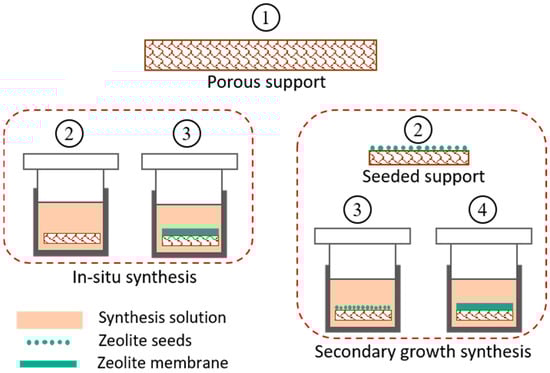
4.2.2. Synthesis of Zeolite Membranes

In membrane separation processes, the thickness of the selective layer has a great influence on the mass transfer resistance to the permeating species. During fabrication of zeolite membranes, the thickness is kept at a few microns in order to minimize the mass transfer resistance. This thin layer can be very fragile; therefore, these membranes are prepared on a porous supports of different materials (alumina or stainless steel) in different configurations such as tubular, flat, and hollow fiber [254,255,256].
Several methods have been developed for synthesizing zeolite membranes on these supports using in situ crystallization and secondary-growth [257,258,259,260]. Both processes work on the principle of hydrothermal crystallization of zeolite particles on a well-prepared support material. A synthesis solution is prepared by mixing required amounts of aluminate and silicate solutions along with other structural directing agents. These agents upon post calcination are removed from inner cavities of zeolite leaving behind porous crystalline structure [261]. For in-situ crystallization, the support is directly immersed in synthesis solution/gel contained in a Teflon lined stainless steel autoclave and kept at a certain temperature. The zeolite crystals grow on support surface by thermally driven crystallization followed by in situ nucleation [257,258]. This method produces non-uniform zeolite layers and is not reproducible, as nucleation and crystal growth processes happen simultaneously.
The second method of secondary-growth crystallization is the most reliable for producing a uniform zeolite layer by separately performing the nucleation and crystal growth steps [259,260], as shown in Figure 5. Nucleation is done by depositing zeolite nuclei (seeds) on support by dip coating or rubbing, before doing final crystallization. This step is more crucial in the secondary growth method and must be carried out carefully to ensure evenly distributed crystal seeds. Many factors such as seed concentration, seed size, coating cycles, coating time, pH and temperature of seed solution are optimized to prepare an optimized seeded support [262,263]. This seeded support is then subjected to hydrothermal treatment similar to in situ crystallization, which provides the seeds as active sites for further growth of zeolite crystals and hence results in a smooth and uniform layer. After successful deposition of zeolite layer on the support, the prepared membrane is subjected to high temperature calcination to strengthen and stabilize the zeolite layer on the support [22,32].
Figure 5. Schematic diagram for hydrothermal synthesis of zeolite membranes [264].

5. Zeolite Membrane Reactors for Methanol Synthesis

Currently, thermally stable membrane materials are being studied for direct water removal from methanol synthesis reactors [24]. Clean methanol is produced from high-purity captured CO2 and green H2 and at the same time, water is the only impurity emerging from the reaction, with other unreacted gases and product methanol. Therefore, in situ water removal from a reaction mixture of CO2, H2, CH3OH and H2O can be achieved by putting water extraction arrangement in methanol synthesis reactor as shown in Figure 6 [34,272,273,274,275].
Figure 6. Schematic representation of zeolite membrane reactor for pure methanol synthesis [34].

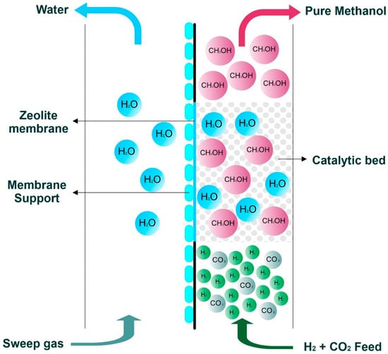
5.1. Effects of In Situ Water Removal on Process Efficiency

A water-selective zeolite membrane capable of bearing the operating conditions of methanol synthesis reactor was deployed for in situ removal of by-product water [34]. The pores of the zeolite membrane, when filled with water molecules due to its intrinsic hydrophilic nature, can efficiently reject even smaller molecules like H2 from passing through it [32]. This in situ water removal is a breakthrough to overcome the thermodynamic limitations of CO2 conversion to methanol. Subsequently, removal of water directly from the reactor has many direct effects on overall process efficiency in terms of increasing CO2 conversion, increasing methanol yield and purity.

5.1.1. Increasing CO2 Conversion and Methanol Yield

Catalytic conversion of CO2 to methanol is an exothermic reaction producing fewer number of moles in products; for example, four moles of reactants give two moles of products [280]. According to Le Chatelier’s principle, there is a need for suitable conditions to shift the reaction equilibrium to forward side, which conditions are low temperature and high pressure. The extreme conditions of these values result in negative effect on large scale production. For instance, low temperature slows down the reaction kinetics of catalytic reaction, while high pressures make the process more expensive. Therefore, the reaction must be performed at moderate conditions to save the processing time, even though at the expense of single pass equilibrium conversion. Borisut et al. found the optimized operating conditions of CO2 hydrogenation to methanol as 183.6 °C and 57.8 bar along with 40 to 45% CO2 conversion [281]. The unreacted gases are recycled back into the reactor to save raw material cost, while having higher overall conversions. Instead of regulating the temperature and pressure, an alternate method to increase the equilibrium conversion can be used to remove the resultant product from the reaction mixture. As per Le Chatelier’s principle, removal of product species pushes the reaction equilibrium towards a forward direction and hence increases the reactant conversion [273]. This phenomenon is utilized in several membrane reactors to achieve high conversion by selectively removing one of the product species [282,283].

5.1.2. In Situ Methanol Purification

By removing the water from methanol synthesis reactor, one can decrease a huge load from downstream methanol purification which is mainly done by distillation [32]. To get high purity of methanol with a simple process, it is necessary to choose a membrane reactor that screens out only H2O molecules. Seshimo et al. reported the production of 95% pure methanol using Si-rich LTA-Zeolite membrane [37].
This in-situ methanol purification by using a water-selective membrane reactor incorporated with zeolite membrane has the advantage of decreasing the load on the final distillation unit. In this way, a relatively smaller distillation unit is required to remove the remaining 5 to 10% of water impurities [32]. This strategy not only saves the plant energy but also cuts down the capital investment by shrinking the equipment footprint. This new technology could be a way forward towards obtaining further high purity of methanol from membrane reactor by developing more efficient membrane materials. 

This entry is adapted from the peer-reviewed paper 10.3390/en16031482

This entry is offline, you can click here to edit this entry!
ScholarVision Creations