Your browser does not fully support modern features. Please upgrade for a smoother experience.
Please note this is an old version of this entry, which may differ significantly from the current revision.
The ongoing energy transition has changed the architecture of electricity networks in ways that conventional power transformers are not able to cope with the new required functionalities. The solid state transformer (SST), which comprises state-of-the-art power electronics with galvanic isolation to interconnect two separate alternating current (AC) or direct current (DC) power grids, is considered to be the dominant solution.
- solid state transformer
- prototypes
- power electronics
1. Introduction
Nowadays, the electric power grid is at a crossroads for the incoming architecture deployment that will be defined in the next few decades. This reconfiguration aims to cope with the planned scenarios regarding the electrification of services such as transport and the increment of renewable energy sources (RES) share. For instance, the European Union has promoted new directives with the goal to increase the installation of distributed energy resources (DERs), as well as to raise their share in the mix of the energy system [1][2]. The SG paradigm, enabling a more flexible and controllable distribution network, is the only way to deal with these new requirements for the electrical grid.
In the near future, the electric power grid will have to handle the interconnection of multiple new sources of generation and consumption, most of them in DC, such as photovoltaic (PV) systems, wind turbines of variable speed control, electric vehicles (EVs), energy storage systems (ESS), or new electric loads associated with domestic or industrial applications [3][4]. Thus, the introduction of hybrid AC/DC grids in power distribution networks seems to be part of the future SG implementation. DC grids have associated several benefits [5]:
- More controllable voltage.
- Direct connections among DC/DC converters, obtaining a more efficient and simpler network.
- Increasing the power carrying capacity to admit more DERs, EVs, etc.
- Longer supply connections without power quality issues.
- Improving the system efficiency.
- Enhancing the network resilience and its problem management.
- Achieving the implementation of more friendly solutions and the use of more sustainable resources in production and operation.
- DC grids can be more economical than AC grids in certain applications.
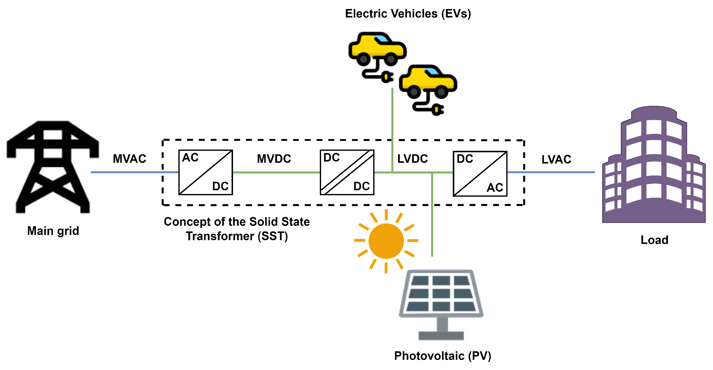
Currently, DC grids are working in high voltage DC connections, DC networks to public transport, shipping, aviation, data centres and so on [6][7]. Further, new technologies such as power semiconductors based on wide band-gap (WBG) materials, the irruption of DC breakers and new systems based on wide monitoring protection and control are enabling the appearance of more DC and hybrid AC/DC power grids. Among them, SSTs are power electronics devices that can interconnect separate electrical grids with different ranges of voltage or frequency providing galvanic isolation between them, thanks to a medium frequency power electronics stage. Hence, they can act as a perfect interface between DC and AC networks, being a key enabler to the introduction of DC and hybrid DC/AC grids. The basic concept of a SST is presented in Figure 1.

Figure 1. Basic concept of the SST.
One of the key concept in SST technology is the medium frequency transformer (MFT). The weight and volume of any transformer depends on its rated frequency. SSTs convert the input and output voltages in medium frequency waveforms by means of different power electronics stages. Hence, the transformer employed to provide galvanic isolation can be more compact and lighter. The converters also allow the voltages at both sides of the MFT to be adjusted, so that the operating point can be controlled. Finally, another common characteristic of a SST is the connection to medium voltage (MV) levels, in contrast to other power electronics that only handle low voltage (LV) levels [8]. Figure 2 shows how, depending on the topology, different electrical networks can be interconnected via a MFT.

Figure 2. Working principle of SST. Different configurations can be obtained depending on the employed power electronics stages.
Many SST topologies have been proposed since it was first patented in 1970. Nevertheless, all these topologies can be grouped into five main categories, derived as combinations of the aforementioned commom concepts [8]:
- Matrix type.
- Isolated back end.
- Isolated front end.
- Isolated modular multilevel converter.
- Single-cell approach.
However, most of the proposed technical solutions and devices remain in a test stage within controlled environments. Hence, some actions are needed in order to state if those solutions can be implemented on a great scale [5][9], especially through pilot demonstrators and innovation projects.
2. Functionalities of SST
SSTs are extremely flexible devices. They allow a wide range of functionalities that could be used for improving the power quality of the grid and provide new services with respect to classic power transformers [10][11]. Some of the more useful SST capabilities are described in the following subsections.
2.1. Waveform Regeneration
SSTs have an independent full-controlled power converter in each side of the device. Therefore, only the energy is transmitted from the input to the output of the device. As a result, possible deviations and disturbances in the waveform on one side are not replicated or transmitted into the other side.
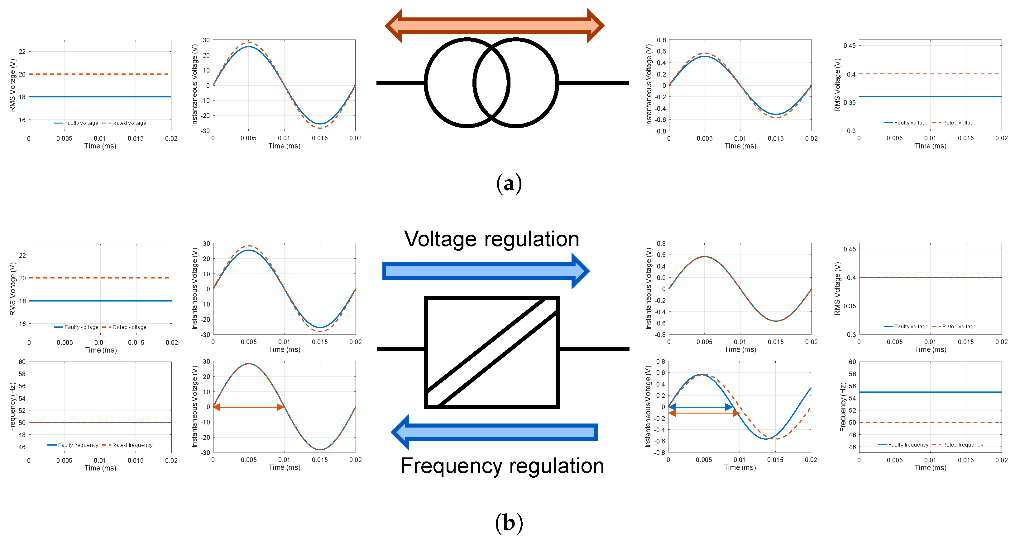
Consequently, imperfections in one side could be removed in the other side, producing the desired output signal. This is shown in Figure 3, where the signal could be restored in either direction [12].

Figure 3. Waveform regeneration feature by a SST device. (a) Harmonics can be transmitted from one side to the other in a classic power transformer. (b) In SST devices, the signal is built up synthetically at both sides and zero harmonics are replicated from the input to the output.
2.2. Smooth Voltage and Frequency Regulation
As described previously, SSTs have an independent full control over the output in each side. This autonomy only requires an energy balance between the primary and the secondary side, because SSTs cannot store energy (except for the limited energy associated with their internal capacitors). Consequently, as long as the energy balance is respected, voltage and frequency excursions in one side could be removed in the other side, producing an output signal at their rated values [13]. This is shown in Figure 4, where the voltage and frequency magnitudes are corrected in the output of the system.

Figure 4. Voltage and frequency regulation feature by a SST device. (a) A classic power transformer has the same voltage and frequency deviations in both sides. (b) A SST is able to smoothly regulate the output in terms of voltage and frequency magnitudes.
2.3. Reactive Power Injection
In SST systems the active power reference is controllable but must be the same for both terminals, in order to keep the energy balance of the whole system. However, SSTs, having a full controlled converter at each side, allow an independent control over the reactive power reference for each winding with any restrictions [14]. Hence, the primary and the secondary side could work in different points of the four-quadrant capability curve (see Figure 5) regarding the reactive power reference, only observing the constraints of the active power flow.

Figure 5. Reactive power injection feature of a SST device. Reactive power can be fixed independently at each side with a four-quadrant capability curve.
2.4. Power Flow Control
As with most full-converter power electronics devices, SSTs are able to work as a voltage or a current source. In addition, SSTs are capable of performing a control over the grid power flow, which depends upon its mode of operation [15].
On the one hand, when SSTs work as current source, they cannot control directly the voltage and frequency outputs of the converter. Nevertheless, they have a complete control over the active power transmission from the primary to the secondary side, and the reactive power injection could be selected freely.
On the other hand, SSTs working as a voltage source are not able to control directly the active and reactive power transmission. However, they have a complete control over the voltage and frequency established at the secondary side, allowing a smooth regulation of these parameters. An indirect power control is also possible by means of regulating at a convenient voltage and frequency.
2.5. Black-Start and Protection Features
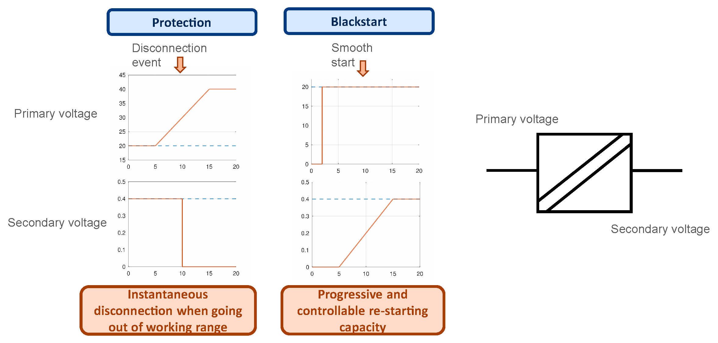
SSTs are fully controllable devices with an actuation time in the order of microseconds. Therefore, several timing and instantaneous thresholds can be programmed according to the use-case requirements. In addition, the disconnection can be performed instantaneously or progressively, thanks to the controllability performance of the device [16]. These features allow SSTs to act as protection devices, isolating a section of the electrical grid via their disconnection.
In the same way, after the clearance of faulty conditions or after a blackout of the primary side, the reconnection of the secondary side can follow a desired ramp, in order to avoid undesirable load peaks that could lead to a new fall of the system [17]. Figure 6 shows this feature, considering the ramps obtained by the SST acting either as a protection or in a power restoration.

Figure 6. Protection and black-start SST features. SSTs can be disconnected instantaneously if a programmed threshold is fired; whenever the power grid comes back again, the re-starting process can be performed in a progressive and controlled way.
This entry is adapted from the peer-reviewed paper 10.3390/electronics12040931
References
- United Nations Framework Convention on Climate Change. Paris Agreement. 2015. Available online: https://www.un.org/en/climatechange/paris-agreement (accessed on 1 February 2023).
- European Commission. The European Green Deal; European Commission: Brussels, Belgium, 2019.
- Kartalidis, A.; Atsonios, K.; Nikolopoulos, N. Enhancing the self-resilience of high renewable energy sources, interconnected islanding areas through innovative energy production, storage, and management technologies: Grid simulations and energy assessment. Int. J. Energy Res. 2021, 45, 13591–13615.
- Apostolopoulos, V.; Giourka, P.; Martinopoulos, G.; Angelakoglou, K.; Kourtzanidis, K.; Nikolopoulos, N. Smart readiness indicator evaluation and cost estimation of smart retrofitting scenarios—A comparative case-study in European residential buildings. Sustain. Cities Soc. 2022, 82, 103921.
- Makkieh, A.; Burt, G.; Alzola, R.P.; Jambrich, G.; Fuchs, N.; Kazerooni, A.; Allais, A.; Preve, C.; Bećirović, E.; Yu, J.; et al. DC Networks on the Distribution Level—New Trend or Vision? CIRED: Liège, Belgium, 2021; p. 113.
- Priebe, J.; Korompili, A.; Voss, J.; Luerkens, P.; Moser, A.; Monti, A.; De Doncker, R.W. DC Grid Technology—Advances in Efficient Power Conversion, Multi-Node Control, and Medium Voltage DC Grid Design and Requirements for Planning. In Proceedings of the PCIM Europe 2019; International Exhibition and Conference for Power Electronics, Intelligent Motion, Renewable Energy and Energy Management, Nuremberg, Germany, 7–9 May 2019; VDE: Nuremberg, Germany, 2019; pp. 1–8.
- Fuchs, N.; Jambrich, G.; Brunner, H. Simulation Tool for Techno-Economic Analysis of Hybrid AC/DC Low Voltage Distribution Grids. In Proceedings of the CIRED 2021—26th International Conference and Exhibition on Electricity Distribution, Online, 20–23 September 2021; pp. 2549–2553.
- Huber, J.E.; Kolar, J.W. Solid-State Transformers: On the Origins and Evolution of Key Concepts. IEEE Ind. Electron. Mag. 2016, 10, 19–28.
- CIGRE Working Group WG C6.31. Medium Voltage Direct Current (MVDC) Grid Feasibility Study; Technical Report; Cigré: Paris, France, 2020.
- Kolar, J.W.; Huber, J.E. Potential Future Applications & Topologies of Solid-State-Transformers (SSTs); Technical Report; Swiss Federal Institute of Technology (ETH): Zürich, Switzerland, 2019.
- Shadfar, H.; Ghorbani Pashakolaei, M.; Akbari Foroud, A. Solid-state transformers: An overview of the concept, topology, and its applications in the smart grid. Int. Trans. Electr. Energy Syst. 2021, 31, e12996.
- Alvarez-Gariburo, I.; Sarnago, H.; Lucia, O.; Burdio, J.M. Design and Optimization of a SiC-Based Versatile Bidirectional High-Voltage Waveform Generator. In Proceedings of the 2022 IEEE Applied Power Electronics Conference and Exposition, Houston, TX, USA, 20–24 March 2022; pp. 1333–1337.
- Zheng, L.; Kandula, R.P.; Divan, D. Soft-Switching Solid-State Transformer with Reduced Conduction Loss. IEEE Trans. Power Electron. 2021, 36, 5236–5249.
- Abu-Siada, A.; Budiri, J.; Abdou, A.F. Solid state transformers topologies, controllers, and applications: State-of-the-art literature review. Electronics 2018, 7, 298.
- Chen, H.; Prasai, A.; Moghe, R.; Chintakrinda, K.; Divan, D. A 50-kVA Three-Phase Solid-State Transformer Based on the Minimal Topology: Dyna-C. IEEE Trans. Power Electron. 2016, 31, 8126–8137.
- Saeed, M.; Cuartas, J.M.; Rodríguez, A.; Arias, M.; Briz, F. Energization and Start-Up of CHB-Based Modular Three-Stage Solid-State Transformers. IEEE Trans. Ind. Appl. 2018, 54, 5483–5492.
- Parks, N.; Dutta, S.; Ramachandram, V.; Hatua, K.; Bhattacharya, S. Black start control of a solid state transformer for emergency power restoration. In Proceedings of the 2012 IEEE Energy Conversion Congress and Exposition, Raleigh, NC, USA, 15–20 September 2012; pp. 188–195.
This entry is offline, you can click here to edit this entry!
