Conservation voltage reduction (CVR) is a potentially effective and efficient technique for inertia synthesis and frequency support in modern grids comprising power electronics (PE)-based components, aiming to improve dynamic stability. In conventional power systems with synchronous generators, CVR utilization strategies aiming to conserve energy are split into two broad categories namely, open-loop and closed-loop techniques. Electromechanical voltage regulating devices, such as on-load tap changers (OLTCs), line drop compensators, and capacitor banks, are used to utilize CVR through open-loop procedures without measuring the voltage as a feedback signal.
1. Introduction
The stability of power systems should be preserved from various time scales, such as steady-state operation, dynamics, and faults transients, in each of which stability requirement should be achieved [
1]. In this light, maintaining the balance between power production and consumption is the key factor. For example, from dynamics point view, instant balance should be held at the time scale of less than to a few seconds in power electronics (PE)-based modern grids. However, stabilizing PE-interfaced modern grids comprising inverter-interfaced distributed generation units (IIDGs) is challenging due to the multiple time scales of the control system of inverters. In addition, the high penetration of intermittent renewable energy sources (RESs) imposes more uncertainties to the grid which makes the stabilization scheme more complicated and more expensive [
2].
The conservation voltage reduction (CVR) technique, which conventionally is used for peak shaving and demand reduction [
4], can be an alternative/complementary solution for improving the dynamics stability. CVR is implemented by reducing the grid voltage which results in a reduction in power consumption based on the load-voltage sensitivity (LVS) [
5]. Meanwhile, by controlling the voltage at the lower end of the voltage tolerance limit in dynamics, and consequently controlling the demanded active and reactive power, CVR can bring an instant balance in power production consumption at the dynamics time scale, resulting in improved grid stability. This is a remarkable achievement thanks to the fast response IIDGs provided that an appropriate control scheme for CVR is designed. Yet, CVR can also be a solution to economic and marketing problems by decreasing power consumption as a part of demand-side management programs in modern power systems.
Recently, CVR application in PE-based modern grids such as microgrids (MGs) comprising IIDGs has gained significant attention [
6]. MGs are popular due to their high efficiency [
7] and reliability in integrating IIDGs including RESs, BESSs, and smart loads (SLs) [
8,
9,
10]. Further, the PE-based equipment is the key component, providing the necessary interface between the distributed energy resources (DERs), BESSs, and SLs to the grid [
11]. However, the high penetration of PE interfaces and lack of physical inertia result in low inertia grids that consequently lead to critical frequency excursion and sharp dynamic instabilities [
12]. CVR can be used as a frequency support approach in MGs with high IIDG penetration, providing the necessary inertia and subsequently addressing transient and dynamic instabilities. Hence, CVR increases the grid’s strength which prevents critical frequency deviations that consequently improve the flexibility and controllability of the micro sources (MSs) [
13,
14].
2. CVR Applications
2.1. CVR Performance and Principles
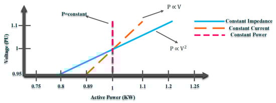
CVR is a low-cost, convenient, and straightforward technology used in power systems employing the basic rules of LVS. Due to the voltage dependency of the demanded active/reactive power, CVR can be adopted to regulate power consumption through LVS and by adjusting the voltage level (voltage Mag. and/or phase). The power flow of a source-load model using ZIP (constant impedance (Z), constant current (I), and constant power (P)) as a common load model illustrates how the LVS basics can be articulated. Note that the ZIP load modeling technique takes into account the time-variant and thermal responses of the load model to the voltage alternation, making it a more accurate load modeling technique for CVR.
The power flow equations, including the injected active and reactive powers delivered from the source to the load terminal as the function of the voltage, can be expressed as follows.
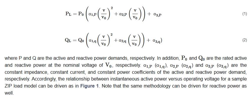
Figure 1. Power dependency on supply voltage for a 1 kW load using ZIP model [
15].
Based on LVS, the voltage sensitivity level varies according to different types of modern power networks as a result of several factors, including the grid’s configuration, load modeling, and the inductance to resistance (X/R) ratio. As illustrated in
Figure 1, different load types exhibit diverse responses to CVR since LVS varies in terms of voltage dependency. CVR applications and impacts heavily rely on the different types of loads connected to the power network, and as a result, load modeling is crucial for CVR development. In light of this, a variety of load-modeling strategies are suggested in the literature, introducing various methodologies [
16].
2.2. CVR Applications in Modern PE-Based Grids
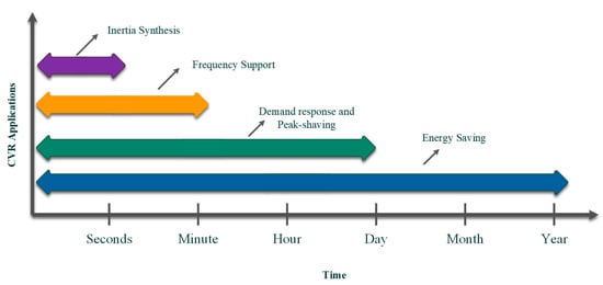
In PE-based grids, CVR is adopted to address both stability and economic issues with a variety of applications over a range of time scales. Categorizing the CVR applications through their time scales provides a new perspective of distinguishing the CVR impact on PE-based grids that leads to using the appropriate CVR implementation techniques, as well as selecting the proper method to quantify and maximize its impacts. An overview of the CVR applications in modern power systems spanning various timescales is shown in Figure 2.
Figure 2. CVR applications in modern PE-based grids at different time scales.
2.2.1. Demand Response, Peak-Shaving, and Energy-Saving via CVR
Reducing desired active/reactive power consumption to save energy is a straightforward CVR use in electric grids. Although the grid configuration and load model have a huge impact on the energy-conserving level, on average, each 1 percent voltage decrease by the CVR is equal to 0.8 percent in the demand power reduction [
21]. As the constant power demand types retain the primary load power while utilizing the CVR and lowering the voltage level, it adversely influences these types of demand, such as the PC desktop, TV, PC monitor, and lighting. As a result, by decreasing the voltage, the current rises, increasing power consumption. From a different perspective, the energy consumption level in closed-loop load models, such as the induction stove, increases by lowering the voltage level, and therefore, by using the CVR, the current increases, leading to an increase in the energy consumption level.
In comparison with energy-saving, the CVR application on demand response and peak-shaving happen during a shorter timescale, whereas the employment methodologies are almost the same. To implement the CVR as an energy-saving and peak demand reduction approach in modern grids, DG sitting and sizing processes by considering limits on the voltage span region can be used to effectively reduce the energy consumption level [
23,
24,
25,
26,
27,
28,
29,
30]. The integration of DG and BESS placement with CVR indicates significant power reduction and increased energy savings, enhancing the system’s functionality and efficiency in the event of a load increase [
31].
2.2.2. Inertia Synthesis and Dynamics Frequency Support via CVR
IIDGs owe their connectivity to the emerging advancements in power-electronics technologies, which raise control and stability challenges. MG concepts have been created in the context of smart grids to address control and management issues associated with the high penetration of RESs. However, due to the absence of rotatory mass in PE-based networks, the lack of inertia is a major problem that causes crucial transient and dynamic instabilities as well as excessive frequency fluctuations [
35]. Inertia is essential for stabilizing the power system and also smoothing the transient and dynamic response of the power grids. Thus, insufficient inertia in PE-based grids directly impacts the frequency nadir (f
min) and the rate of change of frequency (RoCoF), which is defined as follows:
where
H is the inertia constant. It is important to note that pole slipping events that result in critical dynamic instabilities can be caused by
RoCoF ranges between 1.5 Hz and 2 Hz [
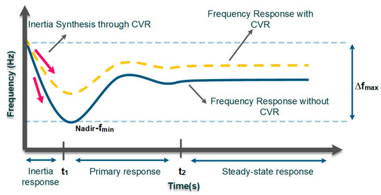
36]. In order to address the aforementioned issues, inertia synthesis and frequency support via CVR is a practical solution aimed at enhancing transient and dynamic stability in PE-based grids (see
Figure 3). As the yellow dashed line illustrates by regulating the demand side voltage level and subsequently the demanded active/reactive power, CVR can boost the inertia level by maintaining an instant balance in power generation and consumption.
Figure 3. Inertia synthesis and frequency support via CVR.
3. CVR Implementation Techniques in Modern Grids
3.1. CVR Implementation in PE-Based Grids (Grid-Connected MGs)
Smart inverters and SLs are used to execute CVR in modern grids and grid-connected inverter-dominated MGs. These techniques, which are novel VVO-based solutions, are intended to implement CVR in massive PE-based power systems that also take into account the influence of RESs and IIDGs [
52].
3.1.1. CVR through Smart Inverters
The smart inverter is a breakthrough technology for integrating DERs, specifically PVs and WTs, as well as BESSs, into modern grids with operational abilities beyond the inverters’ core functions [
53,
54].
Precisely, with the previous consent of the grid operator, IIDGs were permitted to control voltage under the IEEE Standard 1547 by injecting or absorbing reactive power [
56]. Thus, IIDGs can be used as controllable active and/or reactive power sources, and smart inverters can realize their voltage regulation capability. Specifically, the utilities typically restrict the penetration of large-scale PVs and WTs due to their negative effects, such as voltage rise in the distribution network. As a result, smart inverters’ primary application is to solve this problem by regulating the IIDG’s active/reactive power injection or absorption. Depending on the grid configuration, smart inverters may be used to modify the required active/reactive powers of residential-scale loads [
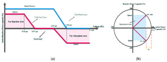
57]. Precisely, the smart inverter follows the volt–var curve defined by the utility in the inductive network with a high X/R ratio, see
Figure 5.
Figure 5. Smart inverter’s characteristics: (a) smart inverter’s volt–var and volt-watt curves; (b) smart inverter’s operational area.
Hence, based on IIDG’s reactive power injection capacity, the VAr injection occurs in case of voltage drops (less than 0.97 pu) and VAr absorption occurs during the voltage rise (over 1.03 pu). On the other side, the smart inverter follows the defined volt-watt curve in the resistive network with a low X/R ratio and the IIDG’s rated active power mitigates during the voltage rise (over 1.03 pu). Note that costume volt–var and volt-watt curves are defined by the utilities for multiple purposes such as the CVR. The autonomous control mode of smart inverters tracks the volt–var and volt-watt curves for voltage regulation [
58].
Smart inverters can also be controlled by designing control rules through data-driven and machine-learning-based methods. Due to higher accuracy and precision when dealing with uncertain grids, machine learning and deep learning techniques have recently attracted a lot of interest [
63,
64,
65,
66,
67]. Smart inverter-based CVR utilization requires high bandwidth communication links (HBWCL). These communication links are responsible for transmitting data such as referenced active/reactive power and voltage values as well as security signals between utility operators, smart inverters, and measuring equipment. Employing data-driven methods can significantly reduce the use of communication links.
3.1.2. CVR through Smart Loads
SLs are PE-based equipment can be used to implement CVR by using voltage regulation capabilities to provide inertia synthesis and frequency support [
76,
77]. Modern PE-based grids use the voltage management capabilities of SLs to modify the required power consumption of large-scale loads to improve the grid’s transient and dynamic responses through CVR.
Electrical loads can be divided into critical (sensitive) and non-critical (NC) types, with the critical loads being unable to withstand a wide range of voltage alternations due to their requirement for uninterrupted, high-quality electricity. In contrast, power consumption in MGs supplying NC loads can be controlled by altering voltage with little to no effect on the consumer. SL is a voltage-dependent NC load connected to a voltage compensator (PE converter with a DC link) that can be employed to inject voltage with controlled magnitude and/or phase angle [
78]. Specifically, the combination of voltage-dependent loads coupled with modern equipment, such as PE interfaced converters or electrical springs (ES), forms an SL compact that gives the capability of controlling load power consumption through CVR [
79]. Note that an ES passes the RES’s fluctuations to NC loads by allowing their power consumption to vary [
80].
3.2. CVR Implementation in Islanded PE-Based MGs
CVR implementation in small-scale islanded MGs is realized through droop controllers [
82]. To regulate voltage and frequency and manage the active/reactive power-sharing process among IIDGs, various types of droop schemes, including the conventional, modified, and adaptive types, are used in PE-based MGs [
83]. Advanced voltage [
84,
85,
86] and power control [
87,
88,
89] methods are utilized in islanded PE-based MGs to develop droop-based CVR to enhance dynamic stability using frequency support techniques.
4. Quantifying CVR Impacts on Modern Grids
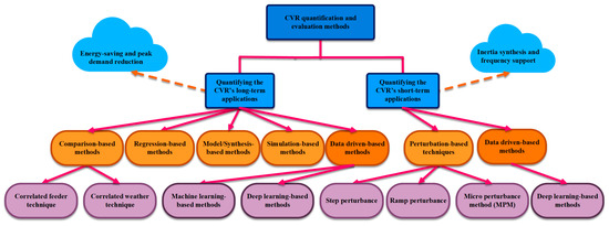
CVR applications in PE-based modern grids should be quantified to represent and evaluate the CVR impacts on voltage, frequency, and demanded active/reactive power. In addition, proposing a benchmark for comparing CVR impacts, enhances the system’s accuracy in selecting the target feeder to maximize voltage reduction amount and consequently maximize the CVR benefits. Classifying the CVR quantification methods based on the CVR application can intensely improve the evaluation methods in terms of finding the proper method, tools, and equipment. Thereby, the overall perspective of the application-based classification of CVR quantification techniques is depicted in Figure 13.
Figure 13. The overall perspective of CVR quantification methods.
4.1. Quantifying the CVR’s Long-Term Applications
CVR factor is commonly used to quantify the long-term CVR applications and can be expressed for active/reactive power as follows [
104]:
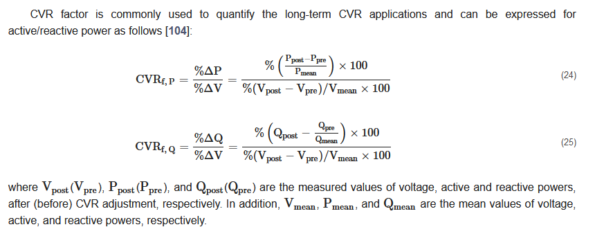
Several CVR-factor derivation techniques concentrate on steady-state time scales that quantify the CVR’s long-term applications, such as energy saving. The following categories apply to these techniques.
-
comparison-based methods;
-
regression-based methods;
-
model/synthesis-based methods;
-
simulation-based methods;
-
data-driven-based methods.
4.2. Quantifying the CVR’s Short-Term Applications
As transients/dynamic stability in modern grids is improved through short-term applications of the CVR (i.e., inertia synthesis and frequency support), quantifying CVR impacts during mentioned time scales is not possible by using traditional quantification techniques with the high penetration of IIDGs. Critical issues and challenges of applying conventional techniques for evaluating CVR short-term applications are listed as follows:
-
A critical issue is with the natural fluctuations of the inverter-interfaced suppliers’ impact in PE-based grids on voltage profile, which distorts the CVR effects. The fast response of the PE-based suppliers and consumers (i.e., IIDGs, and SLs) needs real-time quantification methods. However, the traditional quantification methods are unable to track the CVR impact continuously and in real-time.
-
Further, since all of the traditional quantification techniques outlined in the preceding sections are focused on steady states, they are unable to quantify and follow the effect of CVR on transients and dynamics. Alternative techniques are therefore required to fully quantify and assess the CVR across all time scales.
-
Moreover, distinguishing between the load’s change behavior and the data noise during the transients and dynamics becomes bold. In light of this, a suitable noise reduction methodology, not covered by the other methods, is urgently required for estimating CVR in modern PE-based grids.
Thereby, alternative quantification methods are proposed aiming to address the aforementioned difficulties and problems.
4.2.1. Perturbation-Based Techniques
Perturbation-based approaches are online CVR evaluation frameworks that measure CVR-related load and voltage data in real time to evaluate CVR effects [
128,
129,
130,
131,
132]. Thus, for quantifying the needed data in a continuous manner, proactive voltage perturbation schemes are employed. The perturbation induces the CVR effect; meanwhile, the CVR factor is continuously calculated through experimental data. Note that various perturbation-based quantification approaches utilize various perturbation signals, noise reduction strategies, and CVR quantification indices.
4.2.2. Data-Driven Based Techniques (Short-Term Applications)
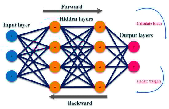
Data-driven methods in quantifying the short-term CVR applications are focused on DNN-based algorithms that show high accuracy in evaluating the CVR impacts [
139,
140]. In light of this, a DNN model with a backpropagation training algorithm is proposed in [
139] to analyze the behavior of the CVR and its effects on the target feeder. As shown in
Figure 21, in a backpropagation-based DNN algorithm the DNN forwards the received inputs and associates them with weights and biases to produce the output. Then, in an iterative scheme, the DNN is trained with a supervised learning approach, in which the difference between the system’s output and a known predicted output as an error is supplied to the training algorithm. Thereby, the weights are updated to minimize the global error driven in each iteration according to the updated weights in a forward and backward algorithm.
Figure 21. Sample DNN with a backpropagation algorithm.
In the proposed DNN-based quantification technique the model is trained through the Levenberg–Marquardt training method which considers day, hour, and whether information as the load profile inputs. The proposed model predicts load savings and creates a CVR baseline. Unlike the similarity-based techniques, the DNN acts as a generative-based scheme to estimate the output load saving. Thereby, the method accuracy is highly increased, making the proposed model a precise quantification technique. In this scheme, the dynamic load behavior can be tracked by the proposed technique which makes the model capable of evaluating the short-term applications of the CVR. The practical result on multiple substations in Washington EMC utility shows high accuracy with 0.22% error in tracking and generating the load during the dynamics change load behavior by the CVR.
This entry is adapted from the peer-reviewed paper 10.3390/en16052502