Your browser does not fully support modern features. Please upgrade for a smoother experience.
Please note this is an old version of this entry, which may differ significantly from the current revision.
Subjects:
Energy & Fuels
Renewable energy solutions are appropriate for on-grid and off-grid applications, acting as a supporter for the utility network or rural locations without the need to develop or extend costly and difficult grid infrastructure. As a result, hybrid renewable energy sources (HRES) have become a popular option for grid-connected or standalone systems. HRES are systems that are reliable, CO2-emission-free, and an effective solution for minimizing dependency on one renewable resource. In attaining a reliable, clean, and cost-effective system, sizing optimal HRES is a crucial challenge.
- hybrid energy system
- reliability analysis
- techno-economic analysis
- optimization methods
- energy storage option
1. Introduction
To be able to reduce global warming, one of the techniques is to raise awareness of the significance of reducing power usage in homes and industries and promote energy-efficient equipment. These concerns are being addressed by numerous researchers in a number of ways. The more dependable, economical, ecologically beneficial, and widespread alternative strategy is to support renewable energy systems and related technologies. The construction of various hybrids of renewable energy sources has received a lot of attention in an effort to enhance long-term energy supply systems. Hybrid renewable energy sources (HRES) are systems that are reliable, CO2-emission-free, and an effective solution for minimizing dependency on one renewable resource, which is important in areas where natural resources are limited [4]. In view of [5,6], the integration of renewable energy resources is an emission-free solution for energy generation that allows energy supply in a district’s topography and also acts as a steady potential energy resource for isolated generation applications. The renewable energy capacity indicated includes large-scale wind, solar, and home photovoltaic (PV) systems. Most residential PV systems are grid-connected, meaning the output receives excess electricity from the grid during the day and sends out power at night. HRES can be utilized independently for each home or in microgrids (MGs), which link a number of residences to create a small power grid in outlying areas where grid expansion is impractical [7,8]. The second method is gaining traction in rural areas and islands [9] because it is cost-effective and can be used alternatively in areas where power infrastructure upgrades are prohibitively costly and fuel transportation is problematic [10]. Many researchers have carried out research to develop hybrids from diverse renewable energy sources in order to improve long-term energy supply systems. According to studies on geographic information systems (GIS), the global population of islands is projected to be over 740 million [11]. Energy consumption has risen in recent years in islands and isolated regions, making reliance on fossil fuels uneconomical. As a result, standalone HRES and RES are viable long-term solutions for clean and cost-effective electricity for expanding populations and enterprises in remote areas and islands [12,13,14].
Since RES generates the majority of its energy from the environment, it reflects the environment’s intermittent character. A significant disadvantage of wind and solar energy is how dependent they are on the environment. However, this issue may be solved by creating an HRES, which combines two or more energy sources with a backup unit [15]. HRES can be used with elements like wind and sunlight that complement each other. Moreover, energy storage systems may be combined with conventional energy sources like diesel generators (ESS). HRES can give a certain application a more cost-effective and steady electrical supply [16,17]. The high initial cost, rising cost of maintenance, fluctuating rates, and depreciation are key difficulties involved with hybrid systems [18]. In addition, HRES design is influenced by the availability of energy sources and site characteristics, as well as by technological and societal limits [19,20,21], which affect the system’s power generation arrangements and total energy production cost.
The appropriate size combination is crucial in this scenario for providing enhanced reliability at the lowest cost. Determining the optimal design of HRES is a difficult undertaking because it is based on data from energy sources, technical specifications, ambient conditions, and load patterns [22]. HRES models, configurations, sizing, and optimization procedures have been investigated for a variety of locations and constraints [22,23,24,25,26].
Some of the optimal sizing challenges associated with HRES systems are estimating system components with the most capacity and at the same time considering feasibility and reliability constraints. It’s worth noting that the HRES grids are expected to be implemented in this analysis, and only optimal generating and storage unit sizing is considered by using optimization methods [49,50]. Such is the case where HRES networks are typically built and developed by governments. Consequently, the distribution of grid installation on HRES systems lacks sufficient data for cost analysis. In addition, generation and storage units are generally located near rural locations, and the HRES grid has a far lower cost than traditional power networks [14,46,51]. Figure 1 depicts a generic technique for HRES system sizing optimization. The system’s input data was used to start the optimal sizing algorithms for HRES system design. The HRES system setup was then defined. The sizing problem was stated using the optimization algorithm. In the next step, the HRES system’s functionality was assessed. After the HRES system became operational, the feasibility limitations were checked for satisfactory results. The objective function was then calculated to complete the optimization problem, provided all the constraints had been met.
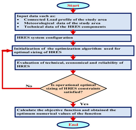
Figure 1. A general approach for optimal HRES system sizing.
2. Hybrid Renewable Energy System Components
HRES has higher upfront costs, regional limitations, and a high degree of intermittency [52]. ESS is required to tackle the intermittency issue, even if the cost of HRES is decreasing [53]. However, the ESS cost is highly significant, especially when large-scale renewable power plants require a lot of capacity. For a cost-effective and ecologically friendly system, a hybrid diesel generator/HRES/ESS combination is recommended. A multi-component hybrid remote area electrification system, on the other hand, is a complex system that necessitates careful planning. In order to produce a reliable, cost-effective system, the concept of optimal planning is paramount. A hybrid renewable system [49,52,53] is the most cost-effective way to store and use natural power without interruption. Due to their dependability and cost-effectiveness in supplying energy to rural and remote areas, researchers have increasingly focused their attention on HRES integrated with ESS. Several studies [54,55,56,57,58] have examined resource utilization and techno-economic performance. Two or more renewable energy generation units, a backup fuel cell power generation unit that is optional, power conditioning units, and a storage unit are all components of an HRES production configuration system [59,60,61,62,63]. The most common schematic diagram of an HRES plant is shown in Figure 2, in which the load is fed first and foremost by solar and wind generators, with the biogas generator serving as a backup. The battery ensures power flow balance in the system as well as optimization.
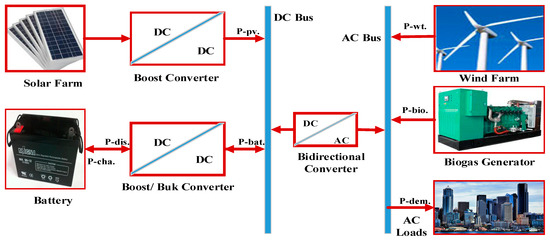
Figure 2. Schematic diagram of an HRES system.
Components using fossil fuels to provide energy, such as diesel or gas generators, contribute considerably to greenhouse gas emissions. A range of renewable energy components has recently become available that can be incorporated with distant area electrification and national grid interconnection systems. The most readily available and appropriate components for far-flung electrical and national grid interconnected systems include solar PV, wind turbines, hydropower, and biogas generators. Their use, however, is strongly dependent on the geographic location of the research site [64,65,66]. Due to the abundance of biomass in rural regions, biogas producers will attract greater attention in the near future [66]. Figure 3 presented the system components in HRES systems.
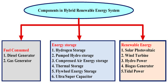
Figure 3. System components in HRES systems.
3. Design Parameters of HRES System
When constructing a hybrid renewable energy system, the most important elements to consider are cost and reliability. These variables are related to emissions and technological challenges. The type of objective function utilized was based on the type of investigation. Often times, economic objectives take precedence. If the project’s budget is limited, reliability becomes a major problem. Emissions have drawn a lot of attention in several situations. Because the objectives are so different, optimal sizing in hybrid renewable energy systems can be achieved by using optimization techniques to solve a single-objective or multi-objective optimization issue. A compromise between the objective functions is required for multi-objective issue solutions expressed as Pareto fronts [67].
As shown in Figure 4, the different categories of objective functions are presented. Nowadays, most researchers give priority to economic factors, then reliability factors, and end with technical and emission considerations. Each of the above objective functions’ categories are explained in detail below.
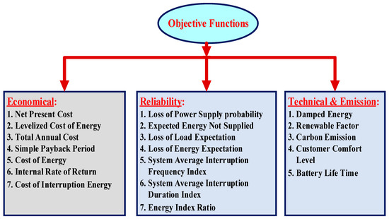
Figure 4. HRES system sizing based on objective functions.
3.1. Objective Functions of Finance
Financial goals include the net present cost (NPC), levelized cost of energy (LCOE), total annual cost (TAC), simple payback period (SPP), and internal rate of return (IRR). The NPC of a diesel generator is calculated by adding up all current capital, maintenance, replacement, salvage, and fuel consumption costs [68]. The capital recovery factor is multiplied by the NPC over the system’s yearly energy consumption to determine the LCOE [69]. To calculate TAC, yearly construction and maintenance costs are compounded by annual fuel prices [70]. The SPP measures how long it will take for yearly profits to cover component capital expenses [71]. The discount rate at which the net present value (NPV) of all future cash flows is zero is known as the IRR [72]. The mathematical formulation of each economic objective function for the hybrid renewable energy system size is as follows:
- (a)
-
NPC: The present value of all benefits and costs that will occur throughout the project’s lifetime is known as the net present cost [73].
- (b)
-
LCOE: It represents the system’s entire yearly cost per kWh of useable electrical energy [74].
- (c)
-
TAC: It is the annualized cost of all power system components, which includes replacement and fuel expenses in addition to capital, operating, and maintenance costs [75].
- (d)
-
SPP: It is the amount of time needed to recoup an investment’s cost [73].
- (e)
-
IRR: In a discounted cash flow analysis, it is a discount rate that sets the net present value (NPV) of all cash flows to zero [76].
3.2. Objective Functions of Reliability Evaluation
The following are some of the most common measurements and target functions for HRES optimal sizing dependability.
1. Loss of power supply probability (LPSP)
2. Expected energy not supplied (EENS)
3. Loss of load expectation (LOLE),
4. Loss of energy expectation (LOEE)
Further, the system average interruption frequency index (SAIFI) and system average interruption length index (SAIDI) are two other dependability indices that have received less attention for optimal sizing of HRES. The likelihood of an unmet load over the whole energy demand of a grid-connected or stand-alone hybrid renewable energy system is known as the LPSP [77]. The EENS is the energy that is supposed to be provided by a hybrid renewable energy system but is not [78]. The LOLE, also known as the loss of load probability (LOLP), is the number of hours per year that the energy exceeds the capacity of the HRE generation system [79]. The LOEE [80] stands for the total energy not delivered by the grid-connected or stand-alone hybrid renewable energy system. Over the course of a year in the HRES project, SAIFI can be defined as the average number of times a client witnesses power outages. Throughout the life cycle of the project, the SAIDI index measures the total average customer’s interruption time. For hybrid renewable energy systems, researchers explain the mathematical calculation of reliability objective functions.
3.3. Objective Functions of Emission and Technical
The following are the other groups of objective functions:
1. Renewable factor (RF)
2. Carbon emission (CE)
3. Battery longevity (BL)
4. Customer comfort level (CCL)
5. Discharged energy (DE)
The RF shows how much of the energy demand is fulfilled by HRES [81]. The CE represents the total quantity of CO2 emitted by the envisaged HRES system over the project’s duration [82]. The BL is the battery’s lifespan in HRES that has been shortened due to deterioration. In order to avoid battery damage and thus increase battery lifetime, a proper installation plan should be developed. The mathematical formulas for emission and technical objective functions are offered in Equations (15)–(19) in the HRES optimal sizing issue. However, the demand response solution has an impact on CCL formulation. The number of hours required to achieve the greatest CCL might be decreased, for instance, if load shifting is considered. The inverter management system, which reduces power fluctuations and provides a consistent power supply, is taken into consideration when calculating the EFR. For the optimum size of a hybrid renewable energy system, the emission and technical objective functions are mathematically formulated.
4. Consideration of Feasibility Constraints
There are two types of feasibility restrictions for hybrid renewable energy system sizing. These include (1) component-related restrictions and (2) system-level technological constraints. The feasibility constraints on remote area electrification and the optimal sizing difficulties of the national grid interconnection system are shown in Figure 6.
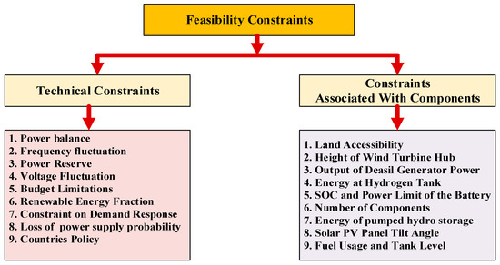
Figure 6. Constraints on optimal sizing of HRES.
This entry is adapted from the peer-reviewed paper 10.3390/en16020642
This entry is offline, you can click here to edit this entry!