While MGs, due to their relatively large size and impact on the development and management of the PG at large, have been the object of significant standardization efforts, NGs—although in a way rather more ubiquitous than the former—are somewhat less clearly defined. Early definitions of NGs, for example, include the following two:
From the architecture point of view, neither definition can be seen as an absolute delimitation of the NG concept. However, the concepts of MG and NG themselves can be seen as misleading due to a direct link to a scale concept. From the grid architecture point of view, it could be easier to define single domain grids, clusters of single domain grids, and power grid.
Irrespective of the definition of choice, a few common—although non-universal—features of both AC and DC NGs are:
These are key factors giving NGs attractiveness in terms of sustainability (thanks to renewable sources such as PV and wind), efficiency (reduced losses due to proximity between energy sources and loads), reliability and resilience (islanding capability—at least for a limited time—thanks to DERs and BESS), and power quality (short-term voltage stabilization provided by BESS).
The increasing diffusion of NG installations and the rapid progress of converter and power semiconductor device technologies make the field of NG converters a very hot and dynamic research area.
2. Nanogrid Architectures
MGs can be classified based on their topology in three major groups, namely, AC, DC, and hybrid [
6,
7], as schematically shown in
Figure 1. NGs can operate as AC, DC, or hybrid structures, too [
5,
8], but they usually have a smaller capacity and serve a smaller area (e.g., a single building or load) [
9,
10,
11].
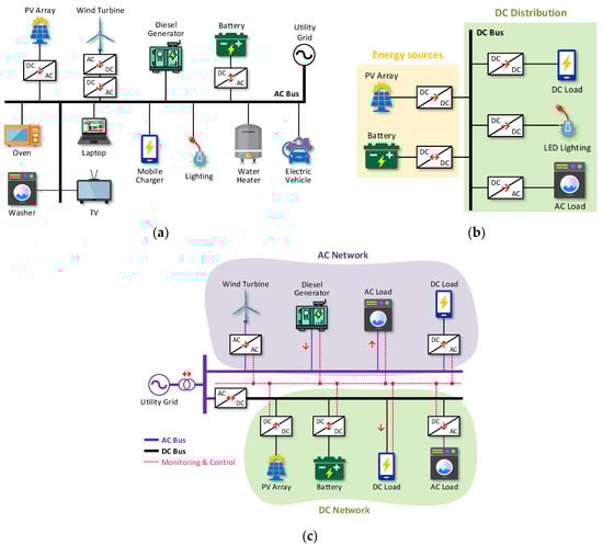
Figure 1. Examples of NG architectures: AC grid (a), DC grid (b), hybrid AC-DC grid (c).
Another common trait between MGs and NGs is the ability to operate both in islanded and grid-connected mode [
5].
Most of the power transmission in the world is based on AC technology, which historically imposed itself on DC transmission mainly thanks to easy transformer-based voltage step-up for long-distance dispatch [
12,
13].
In the case of the AC NG of
Figure 1a, energy flows into the AC NG feeder from the utility grid as well as from DERs that may be DC sources, such as PV arrays or batteries, requiring DC/AC converters; however, AC/DC/AC back-to-back converters are often utilized with AC power sources including wind farms, micro-turbines, or tidal power stations, to adapt the voltage level and frequency produced by the AC generators to the grid requirements [
14]. On the other hand, large segments of residential and commercial loads consist of low power electronics such as personal computers, battery chargers, or LED lighting systems that require AC/DC conversion to be connected to an AC NG.
Connecting these DC loads directly or through high-efficiency DC/DC converters to the bus of a DC NG (
Figure 1b) would reduce the need for energy conversion stages and improve the overall efficiency and reliability of the system [
15,
16]. Recently, DC NGs have thus become increasingly attractive, also due to the improved performance and reduced cost of native DC systems such as PV, BESS, electric vehicles (EVs), and FCs, which can be connected to a DC grid efficiently and reliably [
6,
17]. In fact, avoiding double conversion from DC to AC on the generation side and from AC to DC at the load end, the system complexity is reduced and its efficiency and reliability are increased [
11,
14,
18]. Moreover, the absence of reactive power in DC distribution lines reduces power losses and voltage drops, increases the capacity of electrical lines, and helps to avoid electromagnetic interferences [
14]. In [
19], the transmitted power is found to increase up to a factor of ten moving from AC to three-line DC distribution. Finally, synchronization issues are avoided [
15].
Table 1 summarizes the advantages of the DC NGs over the AC NGs.
Table 1. Advantages of DC NGs over AC NGs.
Future DC NGs will likely use two voltage levels: a high-voltage DC (e.g., 380 V) for home appliances or EV charging, and a low-voltage DC (LVDC) (e.g., 48 V) for supplying computers and low-power electronics [
5,
9,
15,
20], hence the need for efficient DC/DC conversion.
The DC NG is connected to the utility grid via a bidirectional AC/DC converter that has to be properly controlled to compensate for the voltage ripple arising on the DC voltage bus: ref. [
21] discusses a zero-sequence operation mode of the converter and gives a summary of other ripple mitigation approaches.
Refs. [
9,
22] for example considers a commercial power system scenario with a large amount of non-linear loads such as lighting appliances, computers, monitors, adjustable-speed drives for air conditioning, etc. A traditional grid scenario, where each load is supplied in AC, is compared with DC-based architecture demonstrating that the latter is convenient from the efficiency, reliability, and economic points of view. A DC bus voltage equal to the peak value of the standard 230 V AC line is shown to be the best solution for supplying DC native AC loads. This prevents the overload of the input rectifiers of the power supply units by lowering the amount of current flowing.
Ref. [
23] describes a home-level, small power DC NG with AC interface with the PG. A comparison between the modified DC version of the home appliances and the legacy AC ones is carried out in order to show the convenience of the DC distribution. Ref. [
24] also presents a residential-level NG implementation featuring a LVDC bus with an additional AC grid interface. Ref. [
25] demonstrates the benefits of DC migration showing results of efficiency improvements of various system components in a commercial building supplied by 380 V DC and providing local 24 V plugs for small loads.
Finally, a hybrid NG (see
Figure 1c) combines separately controlled AC and DC distribution lines to exploit the advantages of both AC and DC grids [
26,
27,
28]: DC loads and DERs can be connected to the DC bus, while AC loads and DERs can be connected to the AC bus, potentially eliminating the need for DC/AC/DC or AC/DC/AC conversion, thus increasing efficiency and reducing complexity and cost. In hybrid MGs [
29], as for NGs, the design can be optimized to minimize the cost of investments and maximize energy efficiency through the optimal sizing of DERs, loads, and ESSs following different approaches: a combination of different particle swarm optimization (PSO) based algorithms in [
30], a multi-objective optimization of the mathematical model of the MG/NG aimed at minimizing daily energy consumption and greenhouse gas (GHG) emissions [
28], or through a time-of-use approach to reduce the cost of energy [
31].
Ref. [
32] presents a case study of hybrid AC-DC NG, part of a larger campus-level MG. The NG can operate in islanded mode in case of MG faults. The NG is equipped with two sets of PV arrays—separately connected to AC and DC subsystems—and a BESS used by both the subsystems to level-off the PV output power. The DC distribution bus features a 48 V DC voltage while the AC bus is a four wire, three-phase bus with 120 V line-to-neutral voltage. DC/DC buck converters interface a set of PV arrays with the DC subsystem. The other set of PV arrays is connected to the AC subsystem via DC/AC inverters. The AC and DC buses are interlinked through bidirectional AC/DC converters that transfer power between the two subsystems and regulate the bus voltage amplitudes. The NG is connected with the higher-level MG on the AC side.
Most NGs, conceived as the evolution of an existing part of a legacy AC grid, are characterized by a hybrid topology, allowing us to take advantage of the DC distribution while maintaining the possibility to power AC loads and to exchange energy with an upper-level distribution grid (usually in AC).
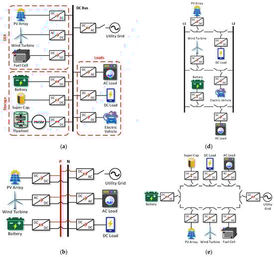
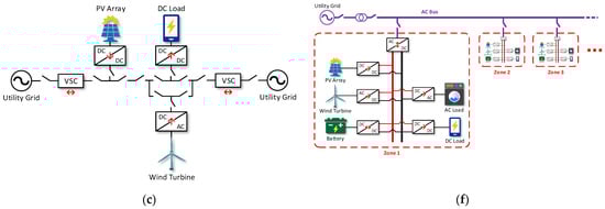
The architecture of a power system impacts its scalability, reliability, robustness, resilience, and cost. This means that it is possible to draw another classification for MGs and NGs considering the type of bus used for power distribution. An interesting comparative analysis of DC MG architectures which can be extended to AC and hybrid MGs and NGs was given in [
33]. Here single-bus (
Figure 2a,b), multi-terminal (
Figure 2c), ladder-bus (
Figure 2d), ring bus (
Figure 2e) and zonal-bus (
Figure 2f) structures are compared in terms of bus voltage levels, BESS connection, inherent stability, expandability to multiple buses, and reliability. Each of these solutions has its strengths and drawbacks, and more research in this area is necessary to reduce their complexity level and solve extant problems. However, in the absence of standardization, numerous optimal system architectures can be defined in relation to the chosen physical variables and to the requirements of the loads.
Figure 2. DC NG classification based on bus structure: single-bus (a,b), multi- terminal (c), ladder-bus (d), ring-bus (e), zonal-bus (f).