2. Review of Synergies between SGE and DHC Networks
According to the EU Directive 2018/2001, “geothermal energy” means strictly “energy stored in the form of heat beneath the surface of solid earth” [
27]. SGE is a specific case where the temperature of the resources is generally under 30 °C (also known as “very-low enthalpy geothermal energy”). In contrast, the heat exchange with surface-water bodies (sea, lakes, or rivers), ambient air, and sewage water is considered as “ambient energy” in the same document. However, unlike in deep geothermal energy (where the heat source is mostly due to the decay of radioactive elements uranium, thorium, and potassium [
28]), the ultimate origin of SGE is actually the energy irradiated by the sun, as in the case of ambient energy. Ambient air, surface water, and the ground all store energy from the sun, but only the ground shows thermal inertia high enough to keep a constant value throughout the year from a depth of 10–15 m downwards. This value corresponds to the yearly ambient temperature of the location close to the surface, and grows with depth according to the geothermal gradient, which is also location-sensitive and ranges typically from 0.02 °C/m to 0.03 °C/m, unless a thermal anomaly is present [
28]. For the same reason, SGE can be exploited either in the form of heat exchange or heat storage. Since the ground temperature is higher than the ambient temperature during winter and lower during summer, heat can be extracted from or injected to the ground for heating + DHW and cooling purposes, respectively, more efficiently than in the case of ambient air or surface water, and with a single machine covering all operation modes.
SGE is a resource available virtually anywhere in Europe, at any time and any size. Typical values of installed thermal capacity (corresponding to the nominal capacity of GSHPs) are 3–10 kW
th for individual households [
29]; 10–100 kW
th for mid-size applications, such as central heating of multifamily buildings and tertiary buildings (private and public offices, commercial, and educational or health centers) [
30]; or 0.1–10 MW
th (and even higher) for very large facilities, such as big hospitals [
31] or airports [
32].
The exploitation of SGE resources requires a ground heat exchanger (GHE) connected to a HP. Horizontal GHEs (also known as “agrothermal collectors”), vertical borehole heat exchangers (BHEs), and thermo-activated foundations (TAFs) are the most common “closed-loop” systems. The term “closed-loop” refers to the fact that the heat-exchanging fluid (usually water or a brine composed of a water–glycol mixture) circulates through a plastic probe embedded in the ground medium. Probe materials are typically high-density or cross-linked polyethylene (HDPE and PEX, respectively). “Open-loop” systems use groundwater directly as a heat-exchanging fluid (GWHEs), although it is usual to separate the ground loop from the building loop via an intermediate HE to minimize corrosion or scaling problems [
33]. Underground thermal energy storage (UTES) is mainly carried out through BHEs (BTES), GWHEs in aquifers (ATES), and in artificial ground cavities (CTES), which mostly correspond to flooded old oil-storage caves or mines (indeed, CTES is also known as MTES). An important difference to stress between heat storage and heat exchange is that the heat carrier flow is bidirectional in UTES systems and unidirectional in exchange systems. This important distinction influences the requirements concerning ground and groundwater properties when it comes to the design, sizing, and operation of GHEs [
34]. Another important difference is that UTES does not imply necessarily the use of GSHPs [
35] and/or the involvement of renewable energy technologies [
36].
2.1. Specific SGE Solutions Applied to Urban Environments
Highly urbanized environments may be seen as a major barrier for SGE projects, given the limited availability of land to drill boreholes and usually intricated underground infrastructure networks. Nevertheless, most European cities possess outstanding examples of successful implementation of SGE projects, from a technical, economic, or environmental perspective.
BHEs are undoubtedly the most versatile, feasible, and environmental-friendly technology to exploit SGE everywhere. At the other extreme, the application of GWHEs is firstly limited by the presence of aquifers with specific characteristics. Generally, more stringent conditions must be met to exploit groundwater for thermal uses because of possible conflicts of use, effects on water quality, microbiology, etc. On the bright side, the investment cost is usually lower compared to BHEs. In the following paragraphs, specific solutions for urban environments are presented.
In urban environments, available land imposes a clear limit to drilling possibilities. Maybe the most obvious solution is to drill as deep as possible to reduce the number of wells, especially when GSHPs are used mainly for heating purposes. This is the case of Sweden, where the average borehole depth has doubled since 1995 [
37]. Sweden shows a large portion of its territory with Precambrian shield rocks (crystalline and metamorphic rocks), and therefore the vast majority of Swedish SGE systems are based on vertical BHEs implemented in hard rock [
38]. As an alternative for non-rocky grounds, the lack of space for drilling can be overcome by shifting from a set of parallel wells to a set of tilted wells, resembling a pyramid-like structure (
Figure 1a). This way, the required surface footprint of the BHE field can be minimized. While the wells’ heads are packed together at the surface, their bottom ends are more distanced, so thermal interferences between BHEs are claimed to show an effective magnitude similar to that of traditional parallel well patterns [
39]. Since 2020, a facility has been in operation at the Schlumberger Riboud Product Center in Clamart, France. The GHE is composed of 10 BHEs, which required less than 20 m
2 for the drilling process.
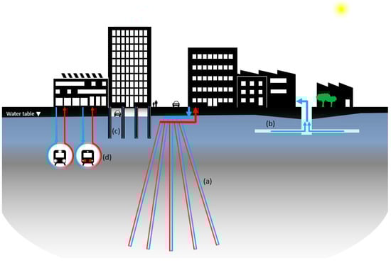
Figure 1. SGE-specific promising solutions in urban environments: tilted BHEs with a reduced surface footprint (a); radial groundwater horizontal wells for GWHEs (b); TAFs (c); and thermally-activated underground metro tunnels (d).
Concerning GWHEs, horizontal wells are a good solution when there are limitations related to the maximum drilling depth of wells and a low hydraulic conductivity takes place or a high extraction rate is wanted, [
40] (
Figure 1b). A good example of their application can be found in the Wirtschaftsuniversität Campus (Wien, Austria), where a set of 10 horizontal extraction wells provide a pumped flow rate of 150 L/s with a maximum drilled depth of 12 m (>3 MW
th installed) [
41]. In urban environments with a shallow groundwater table (near a river, lake, or sea), many dewatering stations are used permanently to keep the structural stability of building foundations or to keep water away from underground infrastructures, such as basements or metro stations. This groundwater abstraction usually represents an external cost due to its pumping towards sewers, but depending on the yearly flow profile, it can be turned into a cost-effective energy source [
42,
43].
A novel concept of GHE is the one called “Dynamic Closed-Loop” (DCL
®) [
44]. It can be imagined as a U-tube probe immersed into an abstraction well, where a forced convection flow is created around the closed loop to enhance its heat exchange rate with the surrounding ground. This is a commercial hybrid solution between GWHEs and BHEs which gets the best of both worlds [
45,
46]. A similar concept has been applied in Japan but taking advantage of an artesian well for the forced convection flow [
47].
Another solution especially relevant in urban environments is that of TAFs [
48]. The use of buildings’ foundations as GHEs (
Figure 1c) is something that can only be taken into consideration in an early stage of the construction project, and it generally applies to large buildings with enough deep foundations, including piles, pile walls, and diaphragm walls, or underground infrastructures, such as metro tunnels [
49,
50] (
Figure 1d). In Barcelona (Catalonia, Spain), the refurbishment of the old Sant Antoni modernist market required a perimeter concrete diaphragm wall, with a total surface of 16,500 m
2 (40 m deep). This massive foundation was employed as a TAF (the largest in Spain up to date) by embedding nearly 44,000 m of PEX probes (O.D. 25 mm SDR11) in the reinforced concrete structure, which yielded a specific heat exchanging rate of 40 W/m
2, allowing an installed power of 750 kW
th that suffices to meet the entire heating demand and 65% of the cooling demand [
51].
UTES systems are not so common as heat exchange systems, although the technology is mature enough [
52]. Its relevance in urban environments is clear since UTES systems are linked mostly to large tertiary buildings or DHC networks [
53,
54]. BTES is postulated as the natural partner for solar thermal energy in small DH networks [
55], allowing the seasonal storage of surplus solar energy during summer for its later use in winter, achieving yearly solar fractions up to 100% [
35] for space heating. For small/individual installations, hybrid concepts, such as solar-assisted GSHPs (SAGSHPs), exploit a similar principle. Especially in heating-dominated installations, the surplus energy from solar thermal collectors during summer can be used to regenerate the ground heat depletion caused by the GSHP during winter. This way, GSHP performance is enhanced, and shorter BHEs are required [
56]. Notice that these systems operate with unidirectional flow and cannot be strictly considered as UTES. However, a heat storage process certainly takes place. Regarding ATES, a low groundwater flow speed (v
gw ≲ 25 m/year) [
57] and a moderate hydraulic conductivity (
K ≳ 10
−5 m/s) [
52] should converge to guarantee low thermal losses. Additionally, injection and extraction wells should be located across the perpendicular direction of the groundwater flow to minimize thermal interferences between them. In contrast, heat exchange systems (unidirectional flow) should install extraction and injection wells upstream and downstream, respectively. CTES, although is the least common of all UTES systems, represents the best chance to reconvert old mines or other artificial underground cavities [
58,
59,
60,
61]. Since groundwater is present as a free-running fluid (not mixed with surroundings rocks), heat injection and extraction show the highest rates among all UTES types, which is attractive for any heat-storage time scale, from daily to seasonal [
62].
GSHPs combined with UTES represent a key element in decentralized and renewable energy generation, especially for intermittent electrical power sources, such as solar photovoltaic (PV) and wind energy. The tandem GSHP + UTES is an efficient and cost-effective alternative to electrical storage (hydroelectric storage or large battery stations). GSHPs can use the surplus electricity from solar PV and wind energy to produce thermal energy, which can be stored in UTES systems for its later use. Although this process downgrades electricity to hot water as the energy vector, the fact is that buildings consume far more thermal energy than electricity for final energy use, so UTES can be seen as a realistic and cheap alternative to electrical storage [
63,
64]. Indeed, this operation strategy is already available as a commercial solution in individual GSHP installations hybridized with solar PV panels [
13,
65,
66,
67,
68]. Instead of storing surplus self-produced power in Li-ion batteries, this electricity is used to produce DHW, which is stored in a tank. By doing so, no matter how less efficient a GSHP can be in producing DHW, the renewable fraction in this case is 100% [
69]. Moreover, the stability of the power grid is favored by reducing the amount of surplus electricity from the solar PV injected into it [
70,
71].
In addition, it is worthy to mention a particular phenomenon that is intrinsic to highly anthropized areas, such as dense urban centers: the subsurface urban heat island (SUHI) effect. This effect is observed through differences in shallow ground temperatures between dense urban centers and the surrounding less-populated areas. The surplus temperature can range between 2 and 6 °C [
72] and supposes a potential energy source that several authors have identified and quantified [
73,
74]. However, the major concern about SUHI might not be its potential as an energy source, but the potential hazards to the chemical quality of groundwater, and its microbial ecosystems [
75]. In this sense, SGE can definitely contribute to mitigate thermal anomalies by balancing the heat exchange with the subsurface thanks to the dual H&C operation modes of GSHPs [
72].
2.2. Modern DHC Installations: 5GDHC Networks
An important aspect for an efficient generation and distribution of energy is the economies of scale. While the power generation model is still based on centralized large plants with long distance transmission and distribution, this concept would hardly apply to thermal energy transported in the form of hot/pressurized steam or water as the energy vector. This is due to thermal and pressure head losses in water pipes, which makes heat transport economically feasible over much shorter distances than electricity, in general no longer than 20–30 km from the production plant to the cluster of consumers [
76]. However, production and distribution of thermal energy at a district level is still the most versatile, energy-, and cost-efficient option over individual installations even if the same primary energy source is considered [
77,
78,
79,
80].
The current geopolitical context, along with climate change mitigation strategies, demands an even faster energy transition towards a 100% renewable-based model. Society must, therefore, switch from centralized, high-power, fossil fuel-based to decentralized, low-power, and renewable energy sources. At the same time, progressive electrification of final energy consumption [
81] and a progressive concentration of the population in cities [
82] are expected. From the H&C perspective, confronting these trends requires adapting the demand to available low-grade, renewable, and local energy sources. The key to this challenge is offered by 5th-generation DHC (5GDHC) networks.
5GDHC networks are those where the heat-exchanging fluid is water or brine at ambient temperature (close to that of the medium through which it is transported, between <0 °C and 20 °C, typically [
83,
84]), and small-to-medium-sized HPs are installed at each building of the network to provide heating, cooling, and DHW. Several review papers have contributed decisively to define the concept and to identify examples around the world [
16,
83,
85,
86,
87,
88,
89,
90,
91,
92]. From these works, the most representative changes with respect to traditional DH schemes are summarized below:
-
Change from centralized generation to distributed generation. This feature favors an easier extension of the network, although at a higher investment cost per connection point.
-
Almost null heat losses due to transport in cost-effective pipe circuits. Since the water/brine temperature is that of the surrounding ground, thermal losses become a minor concern. Therefore, the use of pre-insulated pipes can be avoided, contributing to an important cost reduction. As a counterpart, heat transport by water/brine at ambient temperature implies generally much lower gap between supply and return temperature, thus requiring higher water/brine flows in larger-diameter pipes if compared to high-temperature networks.
-
Buildings conceived either as providers or consumers (prosumers) of heat. Apart from purchasing heat from a network for heating purposes, the same building can now be a supplier by selling the heat rejected when a cooling demand takes place. Monitoring and smart metering are indispensable, analogously as in the case of prosumer electricity, since heat flow requires bidirectional meters in 5GDHC networks, so customers can benefit from purchasing heat or selling it at the right time during the day.
-
There is no longer a centralized source of energy, but a new figure known as the “Balancing Unit” (BU) [
86,
93] which acts as a subsidiary heat provider/absorber of a bidirectional network since, in 5GDHC networks, the priority heat sources and sinks correspond to the buildings themselves. Four generic scenarios can be defined for the BU:
-
Ideal Scenario: H&C loads are compensated between buildings simultaneously, so the heat supplied and rejected in the network cancel each other out.
-
Quasi-ideal Scenario A: H&C loads are compensated, although they do not take place simultaneously.
-
Quasi-ideal Scenario B: H&C loads are not compensated, although they take place simultaneously.
-
Realistic scenario: H&C loads are not compensated between buildings and do not take place simultaneously.
In case 1, the BU would be a dispensable component of the network. In case 2, the BU must be understood as a heat storage unit. In case 3, the BU acts as an additional heat source or sink. Finally, in case 4, which might be the most common scenario, the BU acts as an effective heat source or sink, and eventually as a heat storage unit. A good example is the project Mijnwater 2.0 in Herleen (The Netherlands) [
62] where multiple types of buildings in the network exchange heat between them, and the groundwater in a flooded old mine is used as a heat source and sink but also as a heat storage system.
-
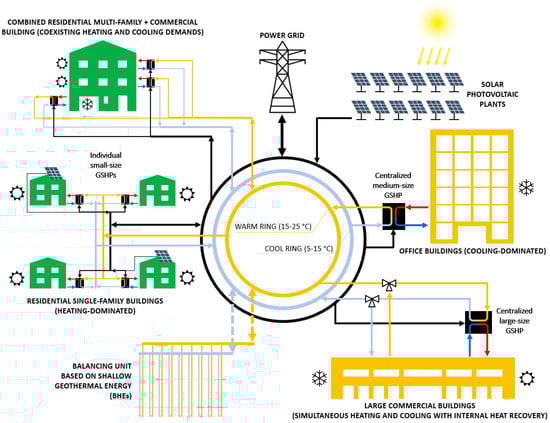
Two pipes are enough. 5GDHC networks are bidirectional, which means that heat can flow into and out from buildings. An important distinction is made between “directed” and “non-directed” medium flow. In directed networks, a central pump station is used to always circulate water/brine in the same direction. The supply line comes from the BU at an ambient temperature, either for heating or cooling purposes, and the return line goes towards the BU. In directed networks, even 1-pipe scheme is possible (and simpler) if all buildings are topologically connected in series [
94]. Under this configuration, the return temperature of a building becomes the supply temperature of the next one. However, for this configuration to be advantageous, the H&C demands need to be well balanced between adjacent buildings, and the extension of the grid is not as simple as in the previous case, where buildings would be connected in parallel. In non-directed networks, each station has its own, decentralized pump station. A warm pipe (15–25 °C) and a cool (5–15 °C) pipe act as the supply and return channels of heating demand substations, while for cooling demand it is just the opposite (see
Figure 2). The direction of the heat-exchanging fluid with respect to the BU is determined by the balance between H&C demand at each moment.
-
No restriction in building typology. Although highly efficient buildings are preferable nowadays under any circumstance, 5GDHC networks do not impose constraints on the type of building for its connection to them. Different degrees of thermal insulation or different emitter technologies (low or high-temperature radiators, radiant floor, fan coils, etc.) can be addressed with tailored HP solutions. Therefore, in the same network, most modern and efficient buildings can coexist along with historical buildings or tertiary buildings of any type or age, with all of them requiring water supply temperatures ranging from 40 °C to 90 °C [
95].
-
In 5GDHC networks, electricity is inextricably linked to heat. Unlike traditional DH networks, where steam or water is the true energy vector by itself, in 5GDHC networks, ambient-temperature water/brine can be an energy vector only if combined with electrically driven HPs. Therefore, parallel concerns about renewable and decentralized electricity generation are indispensable in designing and planning efficient 5GDHC networks.
-
Increased operation complexity. For the operation of bidirectional networks, supply temperature or hydraulic pressure setpoints are not useful anymore. The temperatures of the warm and cool ring can oscillate according to the admissible range of HP performance and the BU (e.g., a BHE field). The actual temperature must be determined by an optimization function. This function considers the balance between H&C demands and a chosen optimization parameter (minimum operational cost, minimum emissions, or maximum HP efficiency, for instance). On the side of hydraulic pressure control, directed networks can be operated as traditional networks. In non-directed networks, the volumetric flow and its direction are mostly determined by the set of decentralized circulation pumps.
-
Flexibility for different business models. In 5GDHC networks, old DH business models cannot apply anymore since electricity and heat are interlinked with prosumers, so new retail tariffs, investment costs, ownership, and operation schemes are necessary. As mentioned above, bidirectional metering of both electricity and heat is the most important technical prerequisite to establish any possible business model for 5GDHC networks. On one extreme, an external investor could own the network, the BU, and the set of decentralized HPs. Then, a one-time connection fee would be applied, a €/kWh price would be charged for consumption, and a different one would be charged for production. At the other extreme, a community of prosumers can associate to invest in a 5GDHC network, letting new prosumers connect to the grid by sharing its costs and ownership, and bearing the investment cost of their own HP. In between these two extremes, there are plentiful appealing choices. The following are some examples:
- ○
-
When the BU is based on a UTES system, a private company that owns the whole infrastructure could charge only for the heating while offering cooling for free as a stimulus to recharge heat depletion.
- ○
-
The network and the BU can be owned by a private company, while an energy service company (ESCO) would own the set of building substations. The final clients would pay only for H&C at an agreed price which, in theory, should be lower than traditional alternatives (gas boilers + air conditioning), but still high enough for the ESCO to obtain a payback for its initial investment plus an additional profit.
- ○
-
The network, the BU, and the substations could be all owned by separate entities. The network would pay the BU owner, and the final prosumers would pay the network owner. Under this scheme, the owner of the BU would pursue maximizing its use with compensated H&C loads on a seasonal basis. The network owner would seek, as its main business driver, to achieve a balanced set of H&C demands on an hourly basis (reducing the need to use the BU). From the side of final prosumers, their main driver would be to compensate their own H&C demands instantly (reducing the need to use the network).
Figure 2. Illustrative scheme of a generic 2-pipe 5GDHC network, where H&C demands could take place simultaneously and the BU is a BHE field. This particular scheme corresponds to a “bidirectional energy flow with non-directional medium flow”, as defined in [
16]. An additional third ring (black-colored) corresponding to electricity has been added to emphasize the coupling of heat and electricity that takes place within 5GDHC networks.
The energy flows of a 5GDHC network are analogous to the heat-recovery processes in large and complex modern buildings, where simultaneous H&C can take place just by pumping heat from the cooling-dominated zone to the heating-dominated one [
96,
97]. From a theoretical perspective, four key performance indicators are identified and defined in [
98] to establish the proper metrics when characterizing and comparing 5GDHC networks:
-
Specific supply costs for H&C. It is defined as a yearly indicator, expressed in €/MWhth/year.
-
Exergy efficiency. It is defined as the ratio between total useful exergy and total exergy expenditures.
-
System COP. This indicator is analogous to that of an individual HP, but it includes the influence of self-produced electricity by means of solar PV panels, denoting the expected close relationship between 5GDHC and renewable electricity generation:
where and are the total H&C demand, respectively; in is the total self-produced electricity injected to the grid; is the total electricity consumed from the grid; and is the total self-produced electricity.
-
Specific CO2 emission. It is expressed as tones of CO2 equivalent divided by MWh of thermal energy (heating + cooling). Here, the emission corresponds to the primary energy used, so it depends on the CO2 factor of the power system mix.
Additionally, a new indicator was proposed in [
98], named Demand Overlap Coefficient (DOC) in order to quantify the proportion of H&C that can be compensated between buildings within a 5GDHC network. DOC shows values from 0 to 1, being 0 for the case where the H&C demands never take place simultaneously, and 1 for the ideal case scenario defined above, when the BU is unnecessary (case 1). This indicator can be either defined for a network or a single building.
2.2.1. Overview of Concept Definition
Among the engineering community, the categorization of DH systems introduced in 2014 by Henrik Lund and co-authors [
14] is nowadays widely accepted. It classifies DH systems into four different generations characterized by a set of disruptive technological and conceptual jumps in chronological order, from their conception in the nineteenth century until the present. These jumps follow a clear trend in the following aspects:
-
Progressive decrease in the supply temperature of the heat-carrying fluid (steam/water) in the network.
-
Progressive increase in the efficiency of the system due to a decrease in thermal losses, both in the generation and distribution of the thermal energy.
-
Progressive transition from fossil fuels to renewable energy sources as the primary energy consumed by the network.
The term “5th generation DHC” (5GDHC) emerged just one year later, in 2015 [
27]. This name was cleverly coined in the wake of Lund’s previous work, with the aim to attract attention to a specific concept of DHC networks. On purpose or not, by naming it with the term “5th generation”, it conveyed a sense of being the natural next step following the abovementioned trends that DHC networks had been showing throughout time (lower temperature, higher efficiency, and higher share of renewables). Furthermore, it added extra features, such as decentralized production and intrinsic coupling between electrical and thermal networks [
99]. Nevertheless, the concept of 5GDHC is not newer than 4th-generation DH (4GDH) in terms of existing operative examples [
16]. However, although its acceptance within Lund’s categorization is controversial [
17,
100,
101], the fact is that 5GDHC has become the most widely and consistently used term for this kind of modern DHC projects [
102]. Particularly, the research European D2Grids project has decidedly contributed to the prevalence of the term “5GDHC networks” over the rest of the nomenclatures. On its webpage, the concept is clearly and concisely stated through a list of five principles [
103].
Simone Buffa and co-authors were the first to provide an exhaustive list of nomenclatures strictly fitting the concept of 5GDHC networks, but also of those corresponding to closely-related types of networks, for the sake of clarification and harmonization [
16,
102]. In the present work, additional comments add to the still open discussion.
The concept of “low-temperature DH” (LTDH) was before Lund’s categorization since it was a natural consequence of trying to lower the supply temperature of traditional DH networks as much as possible (Tsup = 60–70 °C) in order to integrate a larger portion of RTTs, and to lower transmission losses.
The term “ultra-low temperature DH” (ULTDH) has become unfortunately ambiguous. Initially, ULTDH was defined as an evolution from LTDH systems, where the limit of direct supply temperature (still with no booster HPs) was pushed to the lowest possible value (T
sup = 40–45 °C) [
104,
105]. More recently, other authors assimilate ULTDH as 5GDHC networks, where decentralized HPs are an intrinsic part of such concepts [
106,
107]. Although it is accurate to equate the terms LTDH and 4GDH, it is not so with ULTDH and 5GDHC. In [
88], a clear distinction is made between ULTDH and 5GDHC networks, which are defined as ambient-temperature DH (ATDH) networks. In fact, LTDH and ULTDH can be considered as two subcategories of 4GDH [
85], so any reference to “low“- or “ultra-low”-temperature networks should be avoided when referring to 5GDHC networks.
2.2.2. The Synergistic Effect of SGE+5GDHC Networks
Looking at the existing examples of 5GDHC networks in Europe, Simone Buffa and co-authors firstly identified 40 installations in Europe [
16], mostly in Germany and Switzerland, but also in The Netherlands, Belgium, Norway, Italy, and UK. From this list, 25 out of the 40 installations used SGE in their BU. More recently, Marco Wirtz and co-authors updated the list of installations only in Germany, where 53 cases were identified [
84], with some of them being a hybrid system between 4GDH and 5GDHC. In 77% of the surveyed installations, the BU was based on SGE, mainly in the form of horizontal GHEs and BHEs, but also GWHEs. From these examples, it is undeniable that SGE and its associated myriad of exploitation schemes is the natural partner of 5GDHC networks. Interestingly, the first 5GDHC network that could be identified as such by Marco Pellegrini and Augusto Bianchini [
85] consists of a small DHC operative since 1991 that re-uses the groundwater inflow from the Furka Tunnel (Switzerland) as the energy source, in combination with decentralized GSHPs [
108].
This is not in vain as community schemes for the exploitation of SGE are attracting attention in recent years in parallel to 5GDHC networks. In Denmark, the non-profit association Termonet [
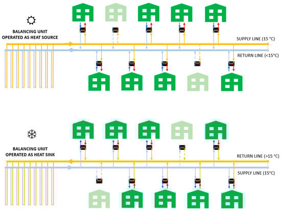
109] is named after a concept that consists of a cluster of customers sharing the same GHEs (BHEs, GWHEs, or TAFs) within a neighborhood. This kind of 5GDHC network is a simplistic version of 5GDHC networks since buildings connected to the grid are alike and usually not showing compensated thermal loads between them (
Figure 3).
Figure 3. Illustrative scheme of a small 5GDHC network. Several residential units with individualized GSHPs and similar demand profiles (not necessarily simultaneous) share a vertical BHE field (BU), as a heat source (above) or as a heat sink (below).
Compared to individualized installations, a shared set of GHEs is advantageous in many ways:
-
Smart and synchronized operation of decentralized HPs permits a lower aggregated peak load in the network, so the total size of the GHEs can be minimized, allowing much lower installation costs, reduced land utilization, lower impact to the ground, and minimized thermal interferences [
110].
-
When integrated in new urbanizing plans, its implementation is the most efficient and cost-effective. However, in existing urban areas, this option might be the only one possible to exploit the SGE resource.
-
As in the general case of 5GDHC defined previously, shared GHEs permit the uptake of new business and operation models.
A representative and outstanding example of a Danish “Termonet” is in Silkeborg, which is operative since 2017. It consists of 15 individual houses sharing 6 × 120 m deep BHEs. The total installed HP power is 90 kW
th (15 units of 6 kW
th each), with no back-up equipment of any kind [
111]. In Denmark, there are 11 Termonet projects (operative or under construction) [
112].
In the UK, the same concept is commonly known as “Shared Ground Loop Arrays” [
113,
114,
115,
116]. In North America, the commercial term GeoGrid
TM [
117] coexists with “GeoMicroDistrict” or “Networked Geothermal Energy”, which were coined by the “Home Energy Efficiency Team” (HEET) located in Massachusetts (US) [
114]. This non-profit organization advocates for a progressive substitution of old and leaky natural gas grids by BHEs [
118]. This is a very interesting approach where many issues converge, such as the mitigation/suppression of greenhouse gas (GHG) emissions from leaks in an extensive old gas pipe grid, the transition from fossil fuels to renewable sources, building electrification, and the shift/renewal of business and jobs. However, the implementation of such a big-scale transformation in energy generation and distribution is not evident, especially in densely packed urban areas. In locations with a markedly vertical distribution of the population (tall and packed buildings), the H&C demand density might be too large to be met by SGE systems, despite the lower demand for multi-family buildings (typically between 20% and 50% less in terms kWh
th/dwelling/year with respect to single-family detached buildings, depending on the year of construction and climate conditions [
119,
120]). Even if all the buildings have been previously enhanced in efficiency, the implementation of large enough GHEs would still be challenging, but not impossible.
In densely populated areas, the exploitation of the SGE resource is more efficient in the form of a DHC network rather than individual installations. Alina Walch and co-authors demonstrated that the exploitation of SGE under a DHC scheme would increase the potential of meeting H&C demands in Western Geneva by 2050, from 63% to 87% for cooling and from 55% to 85% for heating, thanks to direct heat exchange between buildings [
121]. Most importantly, these numbers are independent from the Representative Concentration Pathway (RCP) scenarios defined by the International Panel on Climate Change (IPCC) [
122]. Additionally, it is demonstrated that balanced seasonal ground heat exchange is highly beneficial in order to minimize thermal interference between BHEs, and to maximize the total amount of exchanged heat (comprising both H&C operation modes) along the year.