Your browser does not fully support modern features. Please upgrade for a smoother experience.
Please note this is an old version of this entry, which may differ significantly from the current revision.
The indoor positioning system (IPS) provides continuous real-time localization of objects or people within an enclosed space in different environments, using a network of transmitters and receivers. Indoor localization is more complex than outdoor localization because the indoor communication channel varies significantly with the environment and depends heavily on many factors, such as building structure, room layout, and construction materials.
- indoor localization
- human tracking
- signal measurement
- positioning algorithms
- GPS
- IPS
1. Introduction
Compared with outdoor localization, indoor localization is more complex because the indoor communication channel varies significantly with the environment and depends heavily on many factors, such as building structure, room layout, and construction materials.
Positioning systems can use 2D [1] or 3D [2] models. The latter has a higher positioning accuracy but requires higher costs due to the hardware infrastructure. The lower cost of solutions based on 2D models favors their wide use in applications where accuracy is not to be favored. The technologies usually used in 2D models are Bluetooth, ZigBee, and Wi-Fi. In 3D models, on the other hand, infrared, ultrawideband, and ultrasound are applied. In the field of solutions based on 2D models, the one on fingerprints [3] coupled with Wi-Fi systems applicable for outdoor and indoor positioning is widespread.
There are different indoor positioning systems [4] depending on the technology used, and sometimes they can even be combined (Figure 1). There is no perfect solution; each has its strengths and weaknesses.
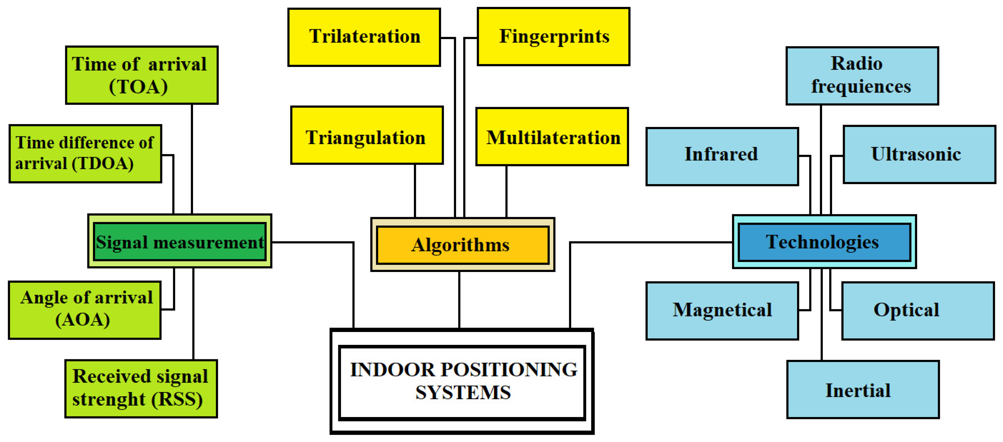
Figure 1. Indoor positioning systems.
2. IPS
The principle of operation of an indoor positioning system (IPS) uses reference sensor nodes with known positions that send a ranging signal to the mobile device attached to the target. Then, the mobile device perceives the request signals and issues a ranging reply to the reference sensor. At this point, the traveling time of the ranging signal between the transmitter sensor node and the moving target can be calculated. The measured data are transferred to a data center using positioning algorithms, and we can determine the target’s exact position. Therefore, for the localization of unknown nodes, we must first measure some metrics and then use the algorithm to calculate the position itself, as shown in Figure 2 [5].
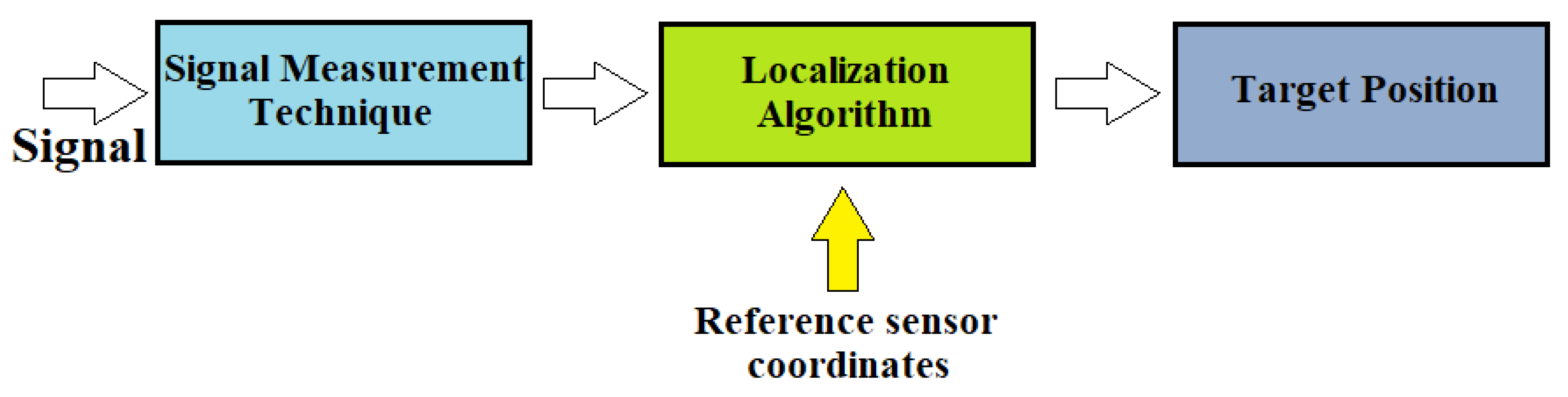
Figure 2. Diagram of the localization process.
In the first phase of the process, between fixed and mobile nodes, all the characteristic information of the signals is exchanged, such as direction, length, time of arrival, and coordinates of the referent node. In the second phase, however, the obtained parameters are transferred to the calculation algorithm to determine the exact position of the moving object.
Positioning systems can be distinguished according to the principle applied, such as proximity, range, and scene analysis.
Proximity uses the maximum received signal strength of an anchor node to calculate the location of the moving node. The near-field communication (NFC) technique is commonly used. We can easily implement the system; however, the accuracy is of a low level.
The range is based on measuring the distance of the communication signals. The location of the target node is determined either according to the direction or distance. For example, the angle of arrival (AoA) is usually applied for the first one. The time parameter (ToA or TDoA) or signal properties (RSSI) can be used for the second.
Scene analysis is a pattern recognition class of methods that uses the characteristics of a scene from a particular viewpoint to match patterns. The currently measured wireless characteristics are compared to prestored characteristics for each pattern to determine a match. Researchers use the best match as the current location of the mobile node. The commonly used method is fingerprinting [3]. The system’s accuracy is excellent but burdensome, as it takes a long time to collect the characteristics needed for each pattern and requires substantial storage space. Moreover, changes to the environment may require the characteristics to be re-evaluated. In recent years, numerous indoor positioning technologies have been developed [6], which differ in the type of hardware used and the localization algorithm. Each has been developed for a specific need and has attributes that make it preferable in certain respects and characteristics or limited by its very nature if used for an application other than that assumed.
3. Signal Measurement Techniques
There are different approaches for this phase, one based on time, another on the receiving angle, and a third on the received signal strength [7].
3.1. Time-Based Methods
3.1.1. Time of Arrival (TOA)
The time of arrival (TOA) [8] method calculates the distance between the emitter and the receiving node considering the time elapsed between the emission and reception of the signal. It is also called time of flight (ToF) because it measures the signal transmission time between the receiver and the transmitter. Knowing the speed of propagation of the signal in the middle and the time taken to get from one point to the other (time of flight or flight time), the space traveled is directly calculable as follows:
where v is the speed of the signal employed, which is the transmission time of the signal received by node i, and Ri is the distance of signal transmission received by node i. Then, the location of the target is estimated using triangulation. For this method to be effective, it is necessary to have three reference points (also called anchors). Graphically representing the system, the node of which we want to calculate the coordinates would be given by the intersection of the three circumferences with the center of the reference nodes (Figure 3). In that case, we would have the following equations:
where (x, y) are the coordinates of the target node.
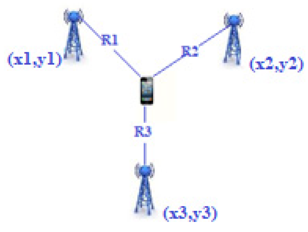
Figure 3. Time of arrival.
This approach, however, has the big flaw of requiring the transmitter and receiver to be synchronized, which is not always feasible. To achieve high accuracy, this issue of the TOA technique can be compensated for by combining it with UWB (ultrawideband, a radio-based communication technology). This technology uses a short pulse duration to filter the signals caused by reflection to improve the overall performance.
3.1.2. Time Difference of Arrival (TDOA)
With this technique, the arrival times of various reference signals are evaluated, and, from the difference in these times, it is possible to determine the location of the target node [9]. The difference in signal arrival time at two reference points is used to calculate the distance difference between the target and the reference points [10]:
where v is the speed of the signal employed, and Δt is the difference in arrival time at each reference point. In two dimensions, this leads to the following form:
where (x1, y1) and (x2, y2) are the known positions of the beacons.
Unlike the TOA, the transmitted messages do not convey a timestamp because the difference in the time of receipt is already sufficient information to guarantee localization. Instead, through the multilateration technique, by comparing the arrival times of the signals in pairs, it is possible to build a system of hyperboles whose intersection determines our position (Figure 4). Unlike TOA, in the TDOA method, not all nodes need to be synchronized; it is sufficient that the anchor nodes are synchronized.
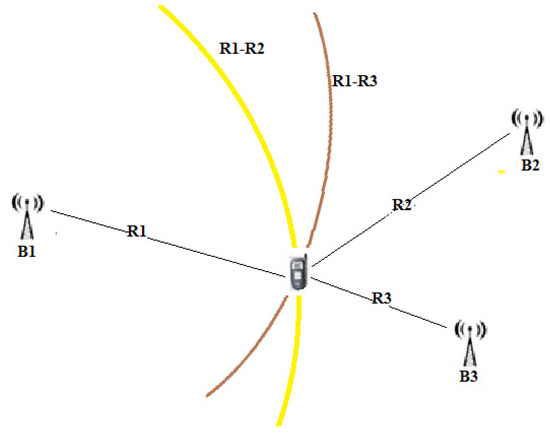
Figure 4. Time difference of arrival.
3.1.3. Round Trip Time (RTT)
The RTT represents the time between sending a signal plus the time required to confirm that signal [11]. In some of its implementations, it is a technology that utilizes the fine timing measurement (FTM) protocol to measure time with picosecond resolution. It allows a mobile device to determine its distance from an access point (AP) by measuring the duration of a time interval of transmission of radio waves traveling back and forth between the transmitter and receiver, which are generally called the initiator and responder. With it, the distance of the target node (R) is obtained with the following equation:
where tRT represents the time of the signal to travel from a node and vice versa, t represents the hardware’s default delay time, and c is the transmitted signal’s speed. This method solves the synchronization problem. Instead of using two local clocks in both nodes to calculate the delay, a single node is used to record the transmission and arrival times. Errors in estimating RTT distance and user location due to factors such as multipath fading occur most often in an indoor environment. The following factors that may be detrimental are related to the topology of the network infrastructure used for the connection between transmitter and receiver:
-
Propagation delay, which depends on the distance between the transmitter and the receiver;
-
Processing delay that depends on the number of nodes on the network. A node can also experience congestion by slowing the connection and increasing the RTT.
3.2. Receiving Angle
Angle of Arrival
This is based on determining the angles between the propagation direction of the received signal and two or more predetermined references [12]. At least two AOA measurements from two different references are necessary to estimate a mobile’s position location (Figure 5). To improve accuracy, three beacons or more are used for position estimation. This measurement can be made using directional antennas or antenna arrays. The position estimation is performed by comparing the carrier phase or signal amplitude across multiple antennas. With AOA, no time synchronization between nodes is required. This technique, however, has limitations because, as distance increases, accuracy decreases. It is affected by the phenomenon of multipath and NLOS.
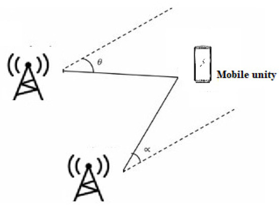
Figure 5. Angle of arrival.
3.3. Connectivity
Received Signal Strength (RSS)
This method is based on the received power of a signal, measured in dBm, and on the relationship between the attenuation of the signal and the distance traveled (Figure 6). Knowing the power with which the signal is emitted and, of course, the power with which the signal arrives at the receiver, it is possible to calculate its attenuation. In fact, since the attenuation of the signal is directly proportional to the distance, with the use of theoretical and empirical models based on the law of signal propagation, it is possible to derive the distance once the attenuation is known [13]. Devices using this technique have the advantage of being low power consumption essential features in the case of WSN (wireless sensor network) nodes, which typically have limited power.
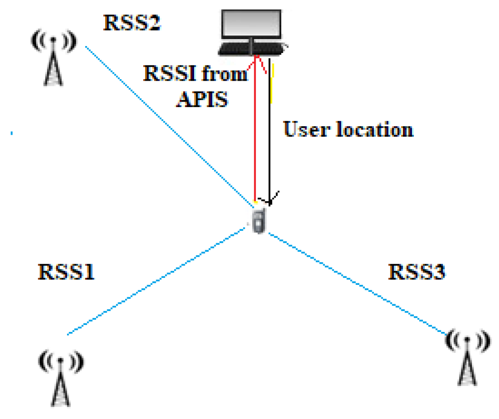
Figure 6. Received signal strength.
The Friis formula can be used to evaluate the signal strength received:
where PR is the received signal power, PT is the transmitted signal power, GR is the gain of the receiving antenna, GT is the transmitting antenna gain, λ is the wavelength (λ = c/f, where c is the speed of wave propagation, and f is its frequency), d the distance in meters, and n the signal propagation constant, also called propagation exponent, dependent on the environment in which we are located.
Considering that the power of the transmitted signal decays with distance, we can modify the previous relationship with the log-normal shadowing model used in wireless communications [14]:
where Pr(d) is the received power at distance d, P0 is the received power measured at reference distance d0, n is the path-loss exponent, and ζσ is the zero-mean Gaussian noise.
Table 1 compares the different signal measurement techniques through their main characteristics.
Table 1. Comparison of signal measurement techniques.
| Technique | Accuracy | Cost | Advantages | Disadvantages |
|---|---|---|---|---|
| TOA | High | High | Scalability, does not require any fingerprint | Needs time synchronization, difficult to implement, produces multipath effects |
| TOP | High | High | No need time synchronization among devices and received nodes, does not require any fingerprint | Requires time synchronization between the received nodes, difficult to implement in narrow bandwidth, multipath effects |
| RTT | High | High | Does not require time synchronization, low complexity | Affected by multipath effects and noise, different processing time delays |
| AOA | Medium | High | No need for any fingerprint, no need for time synchronization, low number of APs | Requires additional directional antennas, decreases in accuracy as distance from source increases |
| RSS | Low | Medium | No need for synchronization, can be used with different technologies, easy to implement | Suffers from multipath effect, noise, can require fingerprint |
4. Localization Methods
In the second phase, through the measured parameters of the signal and the known coordinates of the reference nodes, the coordinates of the unknown nodes can be determined. There are several positioning techniques; among the most important are trilateration, triangulation, multilateration, and fingerprinting.
4.1. Trilateration or True-Range Multilateration
Lateration, also called range measurement, computes the position of an object by measuring its distance from multiple reference positions. It is a technique that calculates the physical position of the target node by knowing the positions of the three fixed non-collinear referent nodes in the 2D space. Finding a location in two dimensions requires distance measurements from three non-collinear points. In three dimensions, distance measurements from four non-coplanar points are required. Using the geometry of the circles, it is possible to determine the positioning of the moving node [15]. Circles are drawn with the coordinates of the reference node as their center and radii equal to the estimated distance, for which, ideally, the target node is located at the point of intersection of the three circles (Figure 7). When more reference points are used than necessary, then we speak of multilateration or true-range multilateration. The circumference can be described through the following equation:
where (xi, yi) are land coordinates of the various centers, and ri is the radius of the i-th circle. Accordingly, the coordinates of the target node can be obtained by solving the following system:
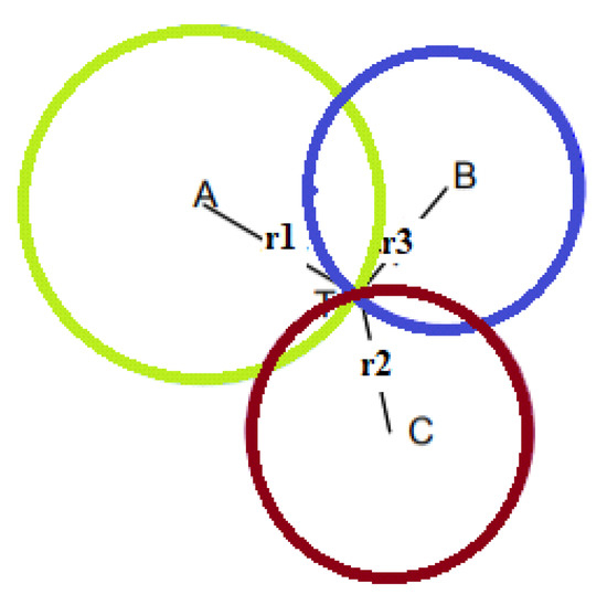
Figure 7. Trilateration.
In practice, since the distance estimated is never perfect, the coordinates of the target node are rarely found at the point of intersection of the three circles; hence, it is likely that it is located within the area of intersection between the circles or even that the circles do not touch. To overcome this drawback, the AML (adapted multilateration) method developed by Kuruoglu et al. can be adopted [16] based on an iterative process applied to the three beacon nodes. Two circles are drawn around two randomly chosen beacon nodes. If the intersection point is unique, the coordinates of this point are acquired. If the circles do not touch, the spokes are increased proportionally to touch each other in one place. If, on the other hand, the two circles touch each other at two points, the one that has a distance from the third beacon closest to the estimate of the distance calculated for this node is chosen. At the end of the iterative process, the average of the coordinates that will determine the position of the target node is calculated.
4.2. Triangulation
Triangulation uses the geometric properties of triangles to compute object locations [17]. When the AOA measurement is available, the triangulation technique can be used to estimate the location of the target node using trigonometric laws [18]. The node at unknown coordinates estimates its angle to each of the two reference nodes and, on the basis of these angles and the positions of the reference nodes, computes its position using simple trigonometrical relationships (Figure 8). The position of the target node can be determined by the intersection of the direction lines of the pair of angles formed concerning the reference nodes (A, B). After obtaining the angles θ1, and θ2, the physical position of T, which represents the target to be located, can then be calculated on the basis of the predetermined coordinates of the reference nodes. In three-dimensional angulation, obtaining a precise position requires one length, one azimuth, and two angle measurements. Triangulation is a complex technique, requiring knowledge not only of the position of beacons but also of their spatial rotation. Therefore, calculations are not more complex than trilateration.
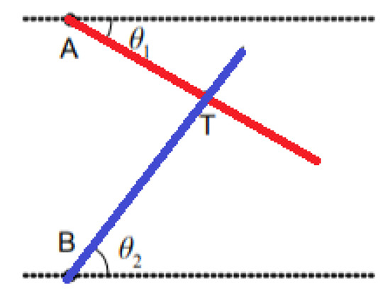
Figure 8. Triangulation.
4.3. Pseudo-Range Multilateration
Pseudo-range multilateration, also known as hyperbolic positioning, is the process of locating an object by accurately calculating the difference in arrival time (TDOA) of a signal emitted by the object to three or more receivers [19]. In this case, the time of emission of the traveling signal is unknown. This technique bases the estimation of the position of a node on the minimization of the difference between the estimated distance via TDOA and the actual distance obtained from the known coordinates. Considering that the time of arrival is proportional to the space traveled by the signal itself, it is possible to identify the position of a target. For example, consider a target that emits a signal in an unknown position with x, y, and z coordinates in an area equipped with a multilateration system with n receivers (P1, P2, …, Pn). The time the signal takes to reach each receiver by the emitter is given by dividing the space by the signal speed assumed as the speed of light c.
Assuming that the point Pn in 3D coincides with the origin of the system, we have that Tn is expressed as
The differences in the time of arrival concerning the reference site are
where (xi, yi, zi) with variables from 1 to n are the known locations of the various receivers. Each of the above equations represents a hyperbola; from the system’s resolution, the emitter coordinates are obtained.
From a graphical point of view, the coordinates of the source can be determined by the intersections of the above hyperbolas, as shown in Figure 9. A hyperbola is defined as a geometric place of the plane having as a constant the difference in distances from the foci that, in our case, are the reference sensor that is the first to receive the signal from the target and the umpteenth sensor that receives the same signal.
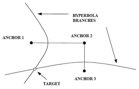
Figure 9. Intersection of hyperboles that identify the position of the target.
In addition, to avoid conflict between the emitters, a minimum separation distance between the various nodes must be ensured by defining a protection zone around each node so that any other node does not infiltrate it.
4.4. Fingerprinting
Fingerprinting is a popular method of localization because of its good accuracy compared to other methods [20]. Traditional fingerprinting is based on RSSI but can also be based on static magnetic field measurements. This technique consists of two phases: a first offline phase of scene analysis and sampling, and a second online phase of pattern matching. In the offline phase, the signals from the different access points are acquired and subsequently stored in a database with the coordinates of the client device. This information can be deterministic or probabilistic. For example, in the online tracking phase, the user’s estimated position is obtained by matching the positions stored in the fingerprint database (Figure 10). Such systems may provide an average accuracy of 0.6 m [21]. Any change in the environment, such as removing or adding furniture, changes the “fingerprint” corresponding to each location; hence, the fingerprint database needs to be updated.
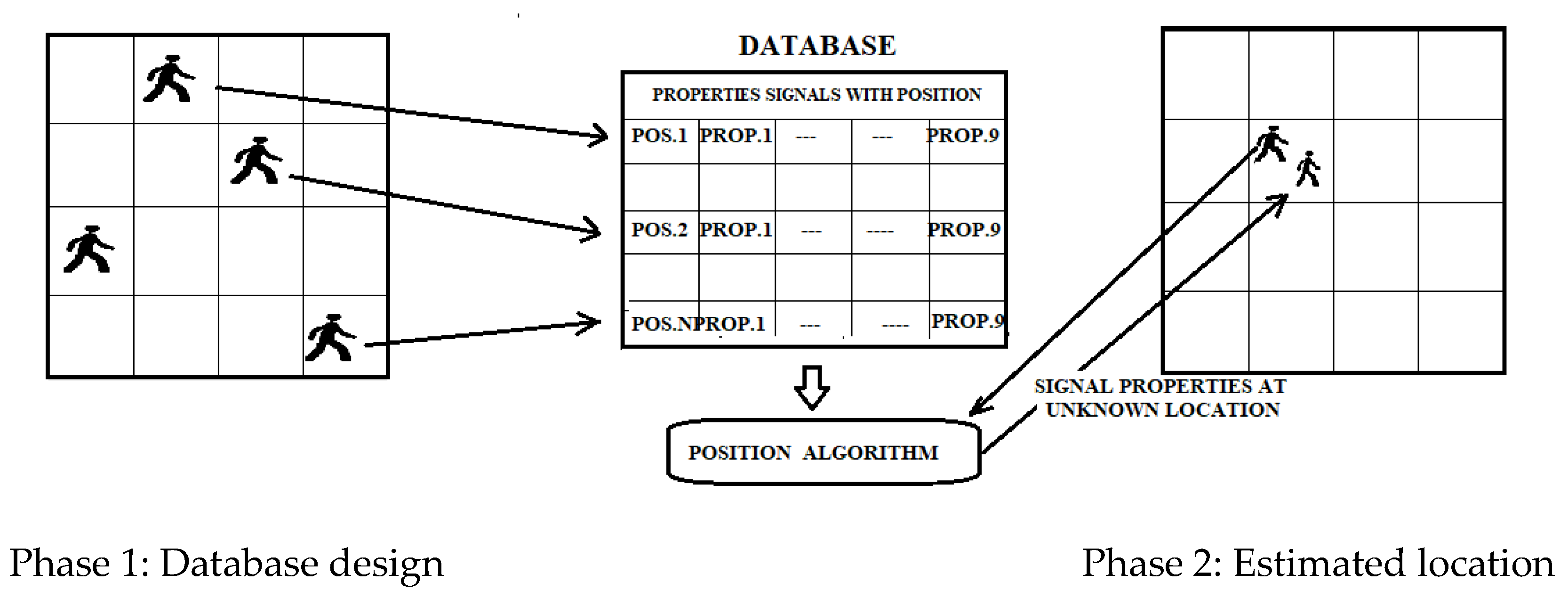
Figure 10. Diagram of the fingerprinting process flow.
5. Signal Technologies
The communication platform used in WSN systems is crucial in assessing that the accuracy of elderly care systems is between 0.5 m and 1 m. The value of the update rate must be at least 5 s. The classification can be made according to the main medium used to determine the position. The technologies used are radiofrequency signals, ultrasound, infrared, optical signals, and inertial measurements.
5.1. Radiofrequency-Based Systems (RF)
Radiofrequency communication is wireless communication with electromagnetic wave frequencies ranging from 3 kHz to 300 GHz [22]. Frequency affects its capabilities such as coverage, penetration, and resistance to obstacles (Figure 11). Therefore, there are three categories of wireless technologies used for different applications: long-distance wireless technology, medium-distance technology, and short-distance technology [23]. RF-based positioning systems can cover long distances because they use electromagnetic waves that are not disturbed by the presence of objects or people. On the basis of this technology, networks such as RFID (radiofrequency identification), WLAN (wireless local area network), Bluetooth, and UWB (ultrawideband) have been created. The first few can be classified as narrowband-based technologies, while the last is a wideband-based technology.
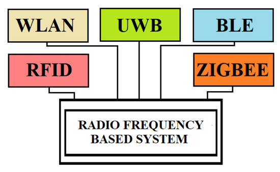
Figure 11. Radiofrequency-based systems.
RFID-based systems use two basic components: readers and tags. Tags can be active or passive depending on the power source. For example, the power supply of a passive tags comes from the electromagnetic energy transmitted by the nearest RFID reader. It cannot send data but only receive it. Active tags are powered by their battery and have a range of action up to 100 m from the reader [24]. Therefore, active RFID tags are helpful for long-range localization and object tracking. However, active RFID technology is unreliable for submeter accuracy and unavailable on many mobile devices. Passive RFID tags do not integrate the battery and backscatter received signal from the base station. Moreover, they are low-cost and require only a chip tag and an antenna. They are suitable for submeter detection and have a detection range of up to 10 m [25].
WLAN often operates according to the standard IEEE 802.11 at 2.4 GHz within the ISM band and has a range of about 50–100 m; however, the 5 GHz is now widely used for transmission due to less interference, less noise, higher constant connection, and higher speed [26].
The above IEEE standard is also known as Wi-Fi from the trademark name of the Wi-Fi Alliance. Wireless local area network (WLAN) technology allows you to connect to a network using radio waves. From an architectural point of view, it can be compared to a local small-scale cellular coverage network with radio transceiver devices such as access points (APs). To increase the connectivity range of a single access point (approximately 100 m) and, thus, be able to cover a larger area, more access points are commonly used, connected with information exchange entirely via radio interfaces, but with a loss in the system’s spectral efficiency. Its wide diffusion is due to mobile devices such as laptops, tablets, mobile phones, and other devices capable of connecting to a wireless network. Wi-Fi technology has an advantage over other technologies thanks to the presence in multiple environments of Wi-Fi access points, and the widespread use of mobile devices enabled by this technology [27]. Therefore, its advantages are as follows: widely distributed hotspots that make indoor positioning services widely usable; wide access freedom, which, thanks to the widespread distribution of existing Wi-Fi infrastructure, does not require network expansion with an apparent reduction in costs; the signals are not severely affected by not line of sight (NLOS). Most WLAN positioning systems are based on RSS, combined with the fingerprinting technique. In general, Wi-Fi positioning techniques can be categorized into four groups: RSSI based, fingerprint-based, AOA-based, and TOF-based. Positioning based on fingerprinting and RSS is the most accurate method but involves building a database, resulting in a more significant workload, and it requires about three or four Apps per 100 m2, making it more expensive. Continuous Wi-Fi scanning consumes a substantial amount of battery power, rendering it disadvantageous for long-term use. This technology is very flexible since, within its radio coverage, nodes can communicate without restrictions. Radio waves can penetrate walls, and senders and receivers can be placed anywhere. Wi-Fi enables the addition of additional users.
BLE (Bluetooth Low Energy) is one of the low-power connectivity standards that operates in the 2.4 GHz ISM band. It can connect devices over a relatively short range, 70–100 m, with 24 Mbps. BLE beacons have the following characteristics: small size, cost-effectiveness, use their battery as a power supply, and can approximately calculate the distance to the beacon, thus estimating the user’s internal location if in the range of more than two beacons [28]. It does not need expensive hardware for accurate localization, and direct LOS is unnecessary. Theoretically, up to 10 cm accuracy can be achieved at distances between beacons and anchors less than 1 m in low-noise environments. BLE is designed with very short ranged wireless transmissions. Adjusting the transmission power makes it possible to extend the range up to 100 m. Although both Bluetooth and Wi-Fi operate in the 2.4 GHz frequency band, there is generally no interference between the signals. Therefore, both technologies can be used in positioning systems to obtain better results by combining their best performances [29]. RSSI and trilateration algorithms are used to determine the exact position of the mobile device [30]. It is a competitive technology thanks to its low energy consumption and good level of accuracy. The latter depends on the Bluetooth node’s stability and indoor propagation’s environmental conditions.
UWB is a radio technology for short-range communications with high bandwidth greater than 500 MHz and a carrier frequency greater than 2.5 GHz, featuring low power consumption [31]. Its large bandwidth allows obtaining a high data transmission speed, short wavelength, and high temporal resolution. Another valuable property of UWB is that signals can easily pass through obstacles. These features have made UWB suitable for indoor wireless positioning. The detection of TOA and time difference of arrival (TDOA), which allow a higher accuracy than other localization algorithms due to the high temporal resolution of UWB signals, where the multipath effect is minimized, are applied to calculate the distance between a reference point and the target. In addition, it is possible to add UWB beacons to existing Wi-Fi infrastructure. The hybrid method combines the availability of Wi-Fi infrastructure, which reduces cost, and the accuracy of UWB when deploying their algorithm; in such hybrid systems, the localization error is limited to 20 cm [32].
ZigBee is a specification based on the IEEE 802.15.4 standard [33]. It uses the 868 MHz bands in Europe, the 915 MHz bands in the United States and Australia, and 2.4 GHz in other regions. ZigBee technology is mainly used for applications belonging to integrated systems provide low transmission speed and low consumption. The ZigBee protocol allows the network to have a reduced expenditure of energy resources by exploiting only the energy contained in the battery incorporated in the individual nodes.
The characteristics of this protocol are IEEE 802.15.4 standard, a speed of 250 kbps, coverage of 10–100 m, and type mesh. It is a short-range communication standard such as Bluetooth and Wi-Fi, which covers a range of 10 to 100 m but differs from those used for high-speed data transmission communication.
The ZigBee IEEE 802.15.4 standard defines two distinct types of devices: FFD (full function device) nodes that can perform all the functions defined by the ZigBee standard and RFD (reduced function device) nodes that can perform only a limited number of functions; in particular, they are nodes that cannot forward traffic to the other nodes, but only act as sources or final recipients of traffic. Communication equipment of the ZigBee protocol is divided into three types: coordination equipment, routers, and terminals. The coordinator is an FFD and is responsible for the overall management of the network, starting the network, setting the parameters of the network, and transferring the packets of the application. It can also be used as a router. The router is used in tree and mesh topologies to expand network coverage. It is usually located either in the central area of the network. Its function is to find the best route to the destination to transfer a message. It can perform the same functions as the coordinator except for the start of the network. The terminal device can be an RFD responsible for collecting and transmitting data. ZigBee nodes consume almost no energy when at rest. ZigBee technology provides three structures: star, tree, and mesh. The star structure is the simplest and consists of a coordinator and a few end devices. The end devices are all connected to a single coordinator node, and all communications pass through this coordinator. The tree topology consists of a coordinator, a few routers, and end devices. Routers allow extending network coverage; end devices are connected in groups to each router and can only communicate with their coordinator. In the case of disabling the latter, the nodes connected to it remain isolated and cannot communicate even with the nearest nodes. The mesh topology, a peer-to-peer network, consists of a coordinator, several routers, and end devices. A mesh topology is self-healing, which means that the node will find an alternative path to the destination during transmission if a path fails. The range of the network can be easily changed by adding or removing multiple devices. Figure 12 shows the three topologies. Commonly, the RSS signal is used to estimate the distance between two or more ZigBee sensor devices [34].
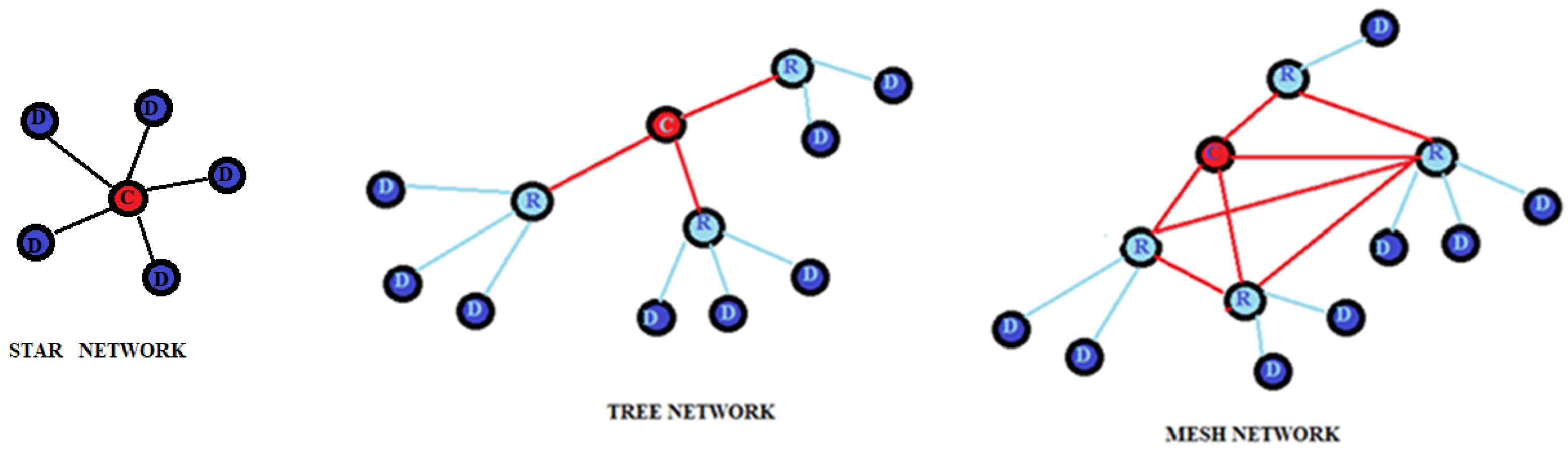
Figure 12. Network topologies.
5.2. Ultrasound-Based Systems
Ultrasonic systems are most commonly used in short-range measurement [35]. The signals have several advantages, such as a slow propagation speed, a negligible penetration in walls, and a low cost of the transducers. They do not interfere with electromagnetic waves and have a relatively short range. Instead, they use building material and air as a propagation medium. The accuracy achieved by ultrasound-based systems is typically a few centimeters. These characteristics are attractive for use in indoor positioning systems. The distance between the beacon and the target node can be calculated by measuring the time of flight (TOF) of the ultrasonic signal, while the Friis formula can be used to evaluate the power budget and the SNR at the target. Using ultrasonic signals, the measurement of time is more accessible than in the case of radio waves due to the lower speed of the acoustic waves and, therefore, the lower temporal resolution required for the measurement itself. The TOF measurement requires a correct temporal synchronization of the network nodes [36].
The target coordinates can be estimated by multilateration concerning some beacons distributed in known places. These systems are called acoustic measurement systems because the systems function using sound waves. Ultrasound is stealthy for the human ear compared to the sound wave. Additionally, this system is associated with RF technology to fulfill the synchronization requirement [37]. Ultrasound has, in addition, several advantages over electromagnetic waves when the application of implantable devices in healthcare is considered. The presence of water in the human body produces attenuation of the RF waves; therefore, it is necessary to increase the transmission power. This increase can be translated into soft-tissue heating because of absorption. This factor increases the size and weight of an implantable sensor. On the other side, the choice of ultrasound technology allows for the creation of implantable sensors at the level of micro-dimensions and low energy consumption [38] due to the relatively low attention to transmitting power to implanted sensors encountered in the human tissues. Furthermore, they are not affected by interference, in the transmission of data for patient monitoring, due to the presence of other electromagnetic devices.
5.3. Infrared-Based Systems (IR)
Infrared (IR) radiation is electromagnetic radiation, the wavelength between 700 nm and 1 mm is greater than that of the visible spectrum but less than that of radio waves [39]. Its main advantage is its wide availability since many devices are equipped with IR sources. However, as they require line-of-sight communication and fail to penetrate opaque obstacles such as walls, their use is limited in individual rooms. It is a very reliable system as light cannot pass through the walls; hence, it is impossible for a tag to detect light from an anchor without being in the same room. It is, however, subject to interference from other sources of IR devices or possibly blinded by direct sunlight. For precise localization, many anchors are required, and we can have difficulties due to the low quality of the signal strength measurements required to calculate the position. Mobile node localization can be used as a measurement method for estimating the angle of arrival of the IR signals [40]. These systems can be divided into two types: direct infrared systems and diffuse infrared systems. The former uses a point-to-point data transmission standard achieving low-power communication. It requires line of sight (LOS) communication or a very short distance between the devices. The latter has a stronger signal than direct IR; it has a more extended reach (9–12 m). It uses wide-angle LEDs, which emit signals in many directions [41]. Another system tested is based on a single photodiode (PD) and multiple LEDs; it uses the angular diversity transmitter, which consists of multiple LEDs and a biconvex lens [42]. Furthermore, systems based on mixed IR and ultrasound [43] or acoustic signatures have been proposed [44].
5.4. Magnetic Field-Based Systems
This technology is used for low-frequency localization. It is based on a platform with a reference station that radiates a magnetic field and a magnetic sensor capable of receiving the radiated field. It is a system that measures position using the Earth’s magnetic field disturbances caused by steel structural elements in a building. Their presence deforms the geomagnetic field in a way that varies spatially but is temporally stable. In known positions, land variations of the geomagnetic field in the indoor environment are recorded to build magnetic maps to be used as fingerprints to identify the positions of an unknown target [45]. It is a method that combines the magnetic field measured by the sensor when the user is in a specific position with the fingerprints present in the magnetic map to estimate the user’s position. However, the accuracy of the location of the magnetic fingerprint can be influenced by the smartphone’s orientation and affected by geomagnetic storms. In addition, it depends on the accuracy of the localization of the magnetic field, the density of fingerprints, and the quality of the acquisition and maintenance process of magnetic maps. Therefore, the current magnetic field positioning technology is mainly combined with other indoor positioning technologies such as Wi-Fi [46] or inertial sensors (IMU) [47] to improve the accuracy. A significant advantage of this type of system is that it offers high accuracy and is not affected by most obstacles; hence, multipath or non-line-of-sight (LOS) errors are avoided. To these must be added the advantages of achieving safety, reliability, and a low cost without additional infrastructure requirements.
The system can use the environmental magnetic fields produced by iron inside reinforced concrete structures of modern buildings that create local variation in Earth’s magnetic field (geomagnetism). Generally, a nonuniform magnetic field produces different magnetic observations depending on the path used. Therefore, positioning can be determined using fluctuations in these environmental magnetic fields. An optimized compass chip inside a smartphone can sense and record these magnetic variations to map indoor locations [48]. Magnetic fields can be generated by a coil powered by alternating current (AC) or pulses of direct current (DC). Electromagnetic fields can also be used to obtain a position by combining the use of electric fields and magnetic fields. The two sources of fields are static charges that produce electric fields and currents which produce magnetic fields. Oscillating charges produce both magnetic and electric fields.
5.5. Optical System
Optical positioning systems can be divided into two main categories: systems in which a moving sensor must be located, whereby reference information is required, and systems in which fixed cameras detect images of moving objects without reference information. In the first case, it is possible to use LEDs that emit light as markers and a series of sensors photodiodes mounted in predefined positions that measure the angle of arrival of the light so that each segment of the space of interest falls within the field of vision of two units [49]. The data collected by the fixed sensors allow for calculating the position of the marker. In the second case, the images acquired by the cameras are combined with computer vision technologies to obtain the object’s positioning [50]. Multiple static cameras can track objects with a high update rate. The obtained accuracies are of the order of tens of micrometers, and the cost of the system increases.
5.6. Inertial System
An inertial system represents the positioning solution based on an inertial measurement unit (IMU) sensor. IMUs combine accelerometers (for measuring linear acceleration), gyroscopes (for measuring rotational speed), and optionally, a magnetometer (for measuring magnetic direction). This information can accurately determine orientation, velocity, and position [51]. This technique qualifies for accuracy, energy, and efficiency, provided that the inertial sensor is attached to the subject’s body. However, the measurements are prone to errors and require using Kalman-type filters. In addition, its cost is relatively high and often requires implementing the network infrastructure. By processing signals from these devices, it is possible to track the position and orientation of a device. The double integration of measured acceleration provides the relative position of an object concerning an initial position. Absolute positioning information may be obtained by fusing INS with complementary sensors. The signal-less localization method is based on mobile sensors such as accelerometer, gyroscope, magnetometer, and barometer, to track users by continuously estimating their displacement using dead reckoning [52]. With this technique, a sensor node uses its previous calculated position for localization at successive intervals. Although dead reckoning can provide the best available information about the current location with simple algorithms, it is subject to significant approximation errors. Another hybrid solution is to host the fake Wi-Fi printing with inertial sensors, overcoming the drawbacks of standalone solutions [53]. Figure 13 shows an architectural schema of an IPS application.
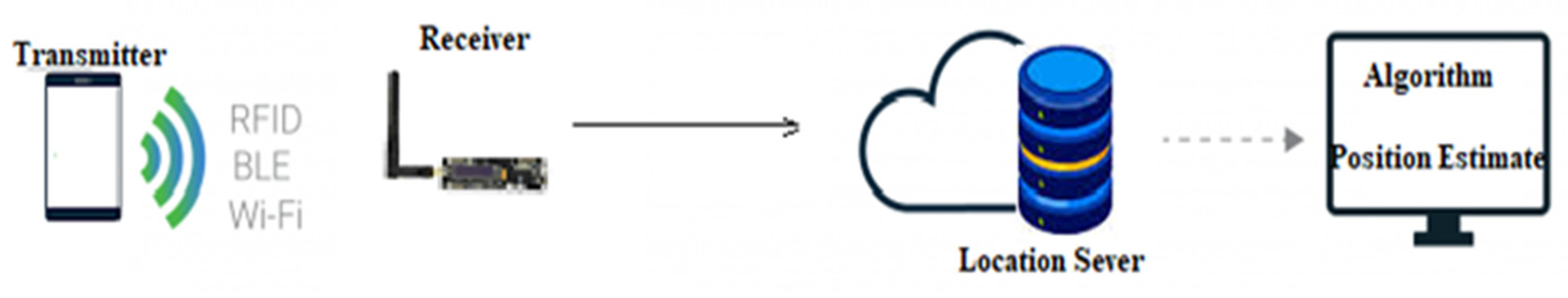
Figure 13. Architecture of IPS System.
Table 2 compares related indoor localization systems.
Table 2. Comparison of indoor localization systems.
| Technology | Measure Method | Cost | Advantages | Disadvantages | Accuracy (m) |
|---|---|---|---|---|---|
| RFID | Proximity, RSS TOA, TDOA, AOA | High | Does not require LOS between TR and RT, simultaneous and fast reading of multiple tags | Small coverage, multipath effect and signal fluctuation, limited capabilities of passive tags | 0.5 (passive) 1 (active) |
| WLAN | RSS, TDOA | Medium | Does not require LOS, presence in multiple buildings, medium scalability | Complex methodology, system redesign in case of changes in the environment | 10–50 |
| Bluetooth | TDOA, RSS | Low–medium | Good accuracy, no need additional infrastructure, does not require LOS, present in most smartphones | RF interference, limited coverage and mobility | 2–15 |
| UWB | TDOA | High | Low energy consumption, high accuracy, passes through walls and any other obstacles | Needs time synchronization, limited coverage, performance degrades in NLOS. | 0.1–1 |
| ZigBee | RSS, AP ID | Low | Low power consumption | Requires special equipment, vulnerable to interference caused by a wide range of signal types | 1–5 |
| Ultrasound | TOA, TDOA | Medium | Good accuracy, not affected by multipath | Interference by high-frequency sound, loss of signal for obstruction | 0.01–0.1 |
| Infrared | AOA, TOA, TDOA | Medium | Low power, no multipath effect, medium accuracy | Does not penetrate walls, requires LOS, sunlight interference, short range | 5–10 |
| Magnetic | AOA, TOA | Medium | Medium power consumption | Requires magnetic field mapping, errors increase with the size of the fingerprinting map | 1–3 |
| Optical | Scene analysis, proximity | Medium | Performance improvement by fusion of image data with data from other sensors | The transformation from the image space into the object space requires additional depth information | 0.1 |
| Inertial | Dead reckoning | Low | Great reliability, reduced size | Cumulative errors, high complexity | Error range 0.5–2% total traveled distance |
This entry is adapted from the peer-reviewed paper 10.3390/s22218119
References
- Huichao, L.V.; Feng, L.; Yang, A.; Lin, B.; Huang, H.; Chen, S. Two-dimensional code-based indoor positioning system with feature graphics. IEEE Photonics J. 2019, 11, 6800115.
- Xu, H.; An, F.; Wen, S.; Yan, Z.; Guan, W. Three-Dimensional Indoor Visible Light Positioning with a Tilt Receiver and a High Efficient LED-ID. Electronics 2021, 10, 1265.
- Subedi, S.; Pyun, J.Y. Practical Fingerprinting Localization for Indoor Positioning System by Using Beacons. J. Sens. 2017, 2017, 9742170.
- Obeidat, H.; Shuaieb, W.; Obeidat, O.; Abd-Alhameed, R. A Review of Indoor Localization Techniques and Wireless Technologies. Wirel. Pers. Commun. 2021, 119, 289–327.
- Gezici, S. A survey on wireless position estimation. Wirel. Pers. Commun. 2008, 44, 263–282.
- Clarify, A.; Al-Salman, A.; Alsaleh, M.; Alnafessah, A. Ultra-Wideband Indoor Positioning Technologies: Analysis and Recent Advances. Sensors 2016, 16, 707.
- Wang, J.; Ghosh, R.; Das, S. A survey on sensor localization. J. Control Theory Appl. 2010, 8, 2–11.
- Ma, Z.; Ho, C.K. TOA localization in the presence of random sensor position errors. In Proceedings of the IEEE International Conference on Acoustics, Speech and Signal Processing (ICASSP), Prague, Czech Republic, 22–27 May 2011; pp. 2468–2471.
- Wu, P.; Su, S.; Zhen Zuo, Z.; Guo, X.; Sun, B.; Wen, X. Time Difference of Arrival (TDoA) Localization Combining Weighted Least Squares and Firefly Algorithm. Sensors 2019, 19, 2554.
- O’Keefe, B. Finding Location with Time of Arrival and Time Difference of Arrival Techniques; ECE Senior Capstone Project 2017, Tech Notes; Tufts University: Medford, MA, USA, 2017.
- Gentner, C.; Ulmschneider, M.; Kuehner, I.; Dammann, A. WiFi-RTT Indoor Positioning. In Proceedings of the 2020 IEEE/ION Position, Location and Navigation Symposium (PLANS), Portland, OR, USA, 20–23 April 2020; pp. 1029–1035.
- Hou, Y.; Yang, X.; Abbasi, Q.H. Efficient AoA-Based Wireless Indoor Localization for Hospital Outpatients Using Mobile Devices. Sensors 2018, 18, 3698.
- Al-Bawri, S.S.; Islam, M.T.; Mandeep Jit Singh, M.J.; James, M.F.; Narbudowicz, A.; Max, J.; Ammann, M.J.; Dominique, M.; Schreurs, M.P. DMMP. RSS-Based Indoor Localization System with Single Base Station. Comput. Mater.Contin. 2022, 70, 5437–5452.
- Wojcicki, P.; Zientarski, T.; Charytanowicz, M.; Lukasik, E. Estimation of the Path-Loss Exponent by Bayesian Filtering Method. Sensors 2021, 21, 1934.
- Pande, S.; Ibwe, K.S. Robust Trilateration Based Algorithm for Indoor Positioning Systems. Tanzan. J. Sci. 2021, 47, 1195–1210.
- Kuruoglu, G.S.; Erol, M.; Oktug, S. Localization in Wireless Sensor Networks with Range Measurement Errors. In Proceedings of the Fifth Advanced International Conference on Telecommunications, Venice, Italy, 24–28 May 2009; pp. 261–266.
- Javed, Y.; Khan, Z.; Asif, S. Evaluating Indoor Location Triangulation Using WiFi Signals. In Advances in Internet, Data and Web Technologies; EDIT 2019, Lecture Notes on Data Engineering and Communications Technologies; Barolli, L., Xhafa, F., Khan, Z., Odhabi, H., Eds.; Springer: Cham, Switzerland, 2019; Volume 29.
- Leelavathy, S.R.; Sophia, S. Providing Localization using Triangulation Method in Wireless Sensor Networks. Int. J. Innov. Technol. Explor. Eng. (IJITEE) 2014, 4, 47–50.
- Sestrem de Oliveira, L.; Kerusauskas Rayel, O.; Paulo Leitao, P. Low-Cost Indoor Localization System Combining Multilateration and Kalman Filter. In Proceedings of the IEEE 30th International Symposium on Industrial Electronics (ISIE), Online, 20–23 June 2021.
- Yu, X.; Wang, H.Q.; Wu, J.Q. A method of fingerprint indoor localization based on received signal strength difference by using compressive sensing. J. Wirel. Com. Netw. 2020, 2020, 72.
- Kotaru, M.; Raj Joshi, K.; Bharadia, D.; Katti, S. SpotFi: Decimeter Level Localization Using WiFi. In Proceedings of the 2015 ACM Conference on Special Interest Group on Data Communication, London, UK, 17–21 August 2015.
- Clegg, F.M.; Sears, M.; Friesen, M.; Scarato, T.; Metzinger, R.; Russell, C.; Stadler, A.; Miller, A.B. Building science and radiofrequency radiation: What makes smart and healthy buildings. Build. Environ. 2020, 176, 106324.
- Liu, J. Survey of Wireless-Based Indoor Localization Technologies; Department of Science & Engineering, Washington University: St. Louis, MO, USA, 2014.
- Zhang, J.; Tian, G.Y.; Marindra, A.M.J.; Sunny, A.I.; Zhao, A.B. A Review of Passive RFID Tag Antenna-Based Sensors and Systems for Structural Health Monitoring Applications. Sensors 2017, 17, 265.
- Chen, C.; Chen, Y.; Lai, H.; Han, Y.; Liu, K.J.R. High accuracy indoor localization: A WiFi-based approach. In Proceedings of the IEEE International Conference on Acoustics, Speech, and Signal Processing (ICASSP), Shanghai, China, 20–25 March 2016; pp. 6245–6249.
- Roy, P.; Chowdhury, C. A survey on ubiquitous WiFi-based indoor localization system for smartphone users from implementation perspectives. CCF Trans. Pervasive Comp. Interact. 2022, 4, 298–318.
- Liu, F.; Liu, J.; Yin, Y.; Wang, W.; Hu, D.; Chen, P.; Niu, Q. Survey on WiFi-based indoor positioning techniques. IET Commun. 2020, 14, 1372–1383.
- Daniş, F.S.; Cemgil, A.T. Model-Based Localization and Tracking Using Bluetooth Low Energy Beacons. Sensors 2017, 17, 2484.
- Subedi, S.; Hwang, S.S.; Pyun, J.Y. Hybrid Wireless Indoor Positioning System Combining BLE Beacons And WiFi Apps. In Proceedings of the International Conference on Information and Communication Technology Convergence (ICTC), Jeju Island, Korea, 21–23 October 2020; pp. 36–41.
- Mussina, A.; Aubakirov, S. RSSI Based Bluetooth Low Energy Indoor Positioning. In Proceedings of the IEEE 12th International Conference on Application of Information and Communication Technologies (AICT), Almaty, Kazakhstan, 17–19 October 2018; pp. 1–4.
- Zuin, S.; Calzavara, M.; Sgarbossa, F.; Persona, A. Ultra-Wide Band Indoor Positioning System: Analysis and testing of an IPS technology. IFAC-Pap. Online 2018, 51, 1488–1492.
- Monica, S.; Bergen, F. Hybrid Indoor Localization Using WiFi and UWB Technologies. Electronics 2019, 8, 334.
- Alvarez, Y.; Las Heras, F. ZigBee-based Sensor Network for Indoor Location and Tracking Applications. IEEE Lat. Am. Trans. 2016, 14, 3208–3214.
- Yan, D.; Kang, B.; Zhong, H.; Wang, R. Research on positioning system based on Zigbee communication. In Proceedings of the 2018 IEEE 3rd Advanced Information Technology, Electronic and Automation Control Conference (IAEAC), Chongqing, China, 12–14 October 2018; pp. 1027–1030.
- Jahren, S.E.; Aakvaag, N.; Strisland, F.; Vogl, A.; Liberale, A.; Liverud, A.E. Towards Human Motion Tracking Enhanced by Semi-Continuous Ultrasonic Time-of-Flight Measurements. Sensors 2021, 21, 2259.
- Carotenuto, R.; Merenda, M.; Iero, D.; Della Corte, F.G. An indoor ultrasonic system for autonomous 3D positioning. IEEE Trans. Instrum. Meas. 2019, 68, 2507–2518.
- Qi, J.; Liu, G.-P. A Robust High-Accuracy Ultrasound Indoor Positioning System Based on a Wireless Sensor Network. Sensors 2017, 17, 2554.
- Santagati, G.E.; Melodia, T. Sonar Inside Your Body: Prototyping ultrasonic intra-body sensor networks. In Proceedings of the IEEE Conference on Computer Communications (INFOCOM), Toronto, ON, Canada, 27 April–2 May 2014.
- Popoola, O.R.; Popoola, W.O.; Ramirez-Iniguez, R.; Sinanović, S. Design of improved IR protocol for LED indoor positioning system. In Proceedings of the 13th International Wireless Communications and Mobile Computing Conference (IWCMC), Valencia, Spain, 26–30 June 2017; pp. 882–887.
- Arbella, D.; Ljubic, S. Indoor Localization Based on Infrared Angle of Arrival Sensor Network. Sensors 2020, 20, 6278.
- Le, G.D. Localization with Symbolic Precision Using Diffuse Infrared Radiation. In Proceedings of the SCC 2015, 10th International ITG Conference on Systems, Communications and Coding, Hamburg, Germany, 2–5 February 2015; pp. 1–6.
- Taylor, M.T.; Hranilovic, S. Angular diversity approach to indoor positioning using visible light. In Proceedings of the IEEE Globecom Workshops (GC Wkshps), Atlanta, GA, USA, 9–13 December 2013; pp. 1093–1098.
- Carotenuto, R. A range estimation system using coded ultrasound. Sens. Actuators A-Phys. 2016, 238, 104–111.
- Fedele, R.; Della Corte, F.G.; Carotenuto, R.; Praticò, F.G. Sensing Road pavement health status through acoustic signals analysis. In Proceedings of the 13th Conference on Ph.D. Research in Microelectronics and Electronics (PRIME), Taormina, Italy, 12–15 June 2017.
- Chen, C.H.; Chen, P.W.; Chen, P.J.; Liu, T.H. Indoor Positioning Using Magnetic Fingerprint Map Captured by Magnetic Sensor Array. Sensors 2021, 21, 5707.
- Wang, E.; Wang, M.; Meng, Z.; Xu, X. A Study of WiFi-Aided Magnetic Matching Indoor Positioning Algorithm. J. Comput. Commun. 2017, 5, 91–101.
- Putta, R.; Misra, M.; Kapoor, D. Smartphone based indoor tracking using magnetic and indoor maps. In Proceedings of the IEEE Tenth International Conference on Intelligent Sensors, Sensor Networks and Information Processing (ISSNIP), Singapore, 7–9 April 2015; pp. 1–6.
- Carbone, P. Magnetic Field Based Positioning Systems. Tech Rxiv 2021.
- Nasir Khan, M.; Jamil, M.; Gilani, S.O.; Ahmad, I.; Uzair, M.; Omer Gőzse, H. Photo detector-based indoor positioning systems variants: A new look. Comput. Electr. Eng. 2020, 83, 106607.
- Morar, A.; Moldoveanu, A.; Mocanu, I.; Moldoveanu, F.; Radoi, I.E.; Asavei, V.; Gradinaru, A.; Butean, A. A Comprehensive Survey of Indoor Localization Methods Based on Computer Vision. Sensors 2020, 20, 2641.
- El-Sheimy, N.; Youssef, A. Inertial sensors technologies for navigation applications: State of the art and future trends. Satell. Navig. 2020, 1, 2.
- Lu, C.; Uchiyama, H.; Thomas, D.; Shimada, A.; Taniguchi, R. Indoor Positioning System Based on Chest-Mounted IMU. Sensors 2019, 19, 420.
- Han, B.B.; Zhao, L. An indoor positioning algorithm based on WiFi fingerprint and inertial navigation system. In Proceedings of the 36th Chinese Control Conference (CCC), Dalian, China, 26–28 July 2017; pp. 6067–6072.
This entry is offline, you can click here to edit this entry!