Your browser does not fully support modern features. Please upgrade for a smoother experience.
Please note this is an old version of this entry, which may differ significantly from the current revision.
Subjects:
Energy & Fuels
The use of piezoelectric-energy harvesting has grown in popularity during the previous two decades. Several implantable energy-harvesting technologies are being developed by scientists to power portable gadgets and medical equipment. Thanks to new technologies, researchers have been able to fabricate highly flexible piezoelectric devices and electronics, paving the way for the development of biocompatible and long-lasting harvesters.
- energy harvesting
- piezoelectric materials
- fluid flow
- wind flow
1. Introduction
Power and electricity generation from piezoelectric materials has been studied for the last few decades [60]. To improve energy harvesting, different techniques have been reviewed. Piezoelectric devices are most broadly used for their simplicity and for being lightweight [61]. In energy harvesting, the energy production from fluid movement is essential. The mechanical energy of fluids is transformed into electrical energy through piezoelectric materials. Different piezoelectric materials can operate and accumulate this energy directly [62]. High-density kinetic energy is relatively available in flowing media, so the K.E of fluids can provide an opportunity to be the power source of electronic devices. Piezoelectric transducers are widely used to transform fluid kinetic energy into valuable electrical energy. Due to the importance of fluid movement in daily life, such as wind and water, energy harvesting from these sources is essential. Energy harnessing from fluid flow has a prominent probability in channels and pipelines [63,64]. Below, the energy harvesting from water and wind is discussed.
2. Wind Flow
Renewable and green energy resources are significant provocations we face nowadays. Vibrations very commonly produce electrical energy by using piezoelectric transducers [65]. Within the energy sources, wind is the encouraging source that is massively used on a large scale for energy production, but less attention is paid on a small scale [66]. Wind energy is inextinguishable and exists almost everywhere in the surroundings. Wind helps in alternative power supplies such as self-driven or automatic wireless sensor networks (WSNs) that need sophisticated monitoring software. Maximizing wind energy usage can generate more power and, hence, reduce the energy crisis. Windmills and wind turbines are commonly used for power generation. The boundary-layer effect and physical hindrances like trees, buildings, and smooth surfaces cause a correspondingly low speed of wind near the surface and act as limitations of energy harvesting [67,68]. In [69], the power generation from wind is illustrated as the impact force generated on the piezo film when power-carrying wind strikes it. An induced electric charge is produced when the wind force generates stress waves in piezo film and a resulting strain in the piezoelectric components. Furthermore, this rectified electric current can be stored in the capacitor, and the stress that produces the current is time dependent.
where ρair is the density of air which is approximately equal to 1.225 kg/m3 at room temperature. At wind speed ν, suppose that the flow is laminar [69].
Some challenges were encountered while recording the wind energy on a micro-power scale for generating sensor nodes: (i) in the region with shunted speed and periodic wind patterns, sensor nodes can be distributed; (ii) sometimes, wind energy harvesters are required to be utilized at a tiny cut-in wind speed (e.g., lower than 2 m/s); and (iii) the voltage level required by electronic devices so that from 1 to 3 V should be delivered by low-speed wind power energy harvesters [70]. The above-indicated challenges can be addressed by the small voltage and maximized power density vibrational frequencies of a piezoelectric energy harvester rather than the low voltage and speed of electromagnetic energy harvesters [71,72,73]. There are several ways by which energy can be harvested from wind, including windmills and wind-turbine-style harvesters, flutter-style harvesters, vortex-induced vibrations, and galloping.
2.1. Windmills and Wind-Turbine-Style Harvesters
Because of wind availability and its continuous mechanical energy, harvesting energy from wind seems more attractive than from many other sources. Tien and Goo proposed a single PZT composite cantilever windmill harvester concept in 2010 [74]. A standard fan with exciter teeth was attached to the turbine’s shaft to gather energy. A different harvester model was built in a wind tunnel with several bimorphs installed. Yang et al. [75] also presented a novel windmill harvester design with a rotating fan polygonal arrangement. It consists of 12 piezoelectric bimorphs and 3 steel balls inside the polygon. As shown in Figure 2, power will be produced when the wind rotates the windmill, resulting in the piezoelectric energy harvesters being stuck with the steel balls.
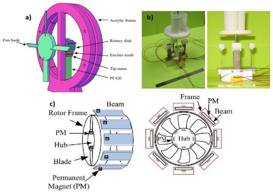
Figure 2. (a) Windmill with exciter teeth; (b) piezomagnetic windmill with no contact; (c) multi-magnet windmill with no connection [76].
Power generation by centimeter-scale windmills was inspected by Rancourt et al. [76]. An electromagnetic transduction mechanism was used to produce power. Three propellers with a diameter of 4.2 cm and four blades having different pitch angles were tested as prototypes in the wind tunnel. This experiment’s result shows that the “Schmitz theory” of substantial wind turbines applies to the smallest-scale wind turbines, but there is a sharp decline in the power generation at low wind speed because of frictional losses in internal electric resistance and the generator. Similarly, several other studies on windmills and wind turbines were accomplished by Bansal et al. [77], Howey et al. [78], Priya et al. [79], Karami et al. [80], Bressers et al. [81], Chen et al. [82], and numerous others.
Their studies show that all of them use windmills and turbines having different numbers of bimorphs. Some of them change the alignment of these bimorphs from circular to perpendicular. Compared to circular arrays, they were far easier to fabricate and were space efficient. Still, their drawback was that dissipation of kinetic energy occurs and mechanical damage is caused by the fatigue issues of piezoelectric cantilevers. So, to reduce this issue, a few introduced magnetic interaction by using a magnet at the tips of transducers. High output power, small cut-in wind speed, and a hefty operative range of wind speed can be obtained by both conventional and non-uniform parametric excitation techniques. Figure 3 and Figure 4 show the schematics and graphs of small-scale windmills and wind turbines.
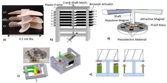
Figure 3. (a) Testing of three propellers with different pitch angles; (b) pictorial view of rectangular piezoelectric windmill; (c) schematic of optimized three-fan blades in rectangular piezoelectric windmill; (d) contactless piezoelectric wind-turbine schematic featuring magnetically driven piezoelectric elements; (e) unregular piezoelectric wind-turbine schematic with parallel and circular configurations [83].
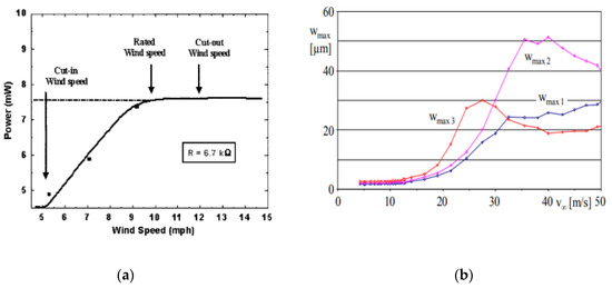
Figure 4. (a) Wind speed for the piezoelectric windmill with the variation in power; (b) at a wind speed of 40 m/s, measured voltage and power vs. external load using Series 1 and 2 cantilevers, with index “short” indicating L/D = 2.125 and “long” showing L/D = 5.057 [83].
2.2. Flutter Style Harvesters
Flutter is an evanescent structure aeroelastic instability in an exceedingly fluid flow. Different kinds of flutters can depend on categorizing their excitement and nourishment mechanisms [84]. Flutter-style harvesters are the second most detailed layouts from energy harvesting to the flowing fluid. Several problems related to windmill-style harvesters using harvesters containing the flutter style were observed, including intricacy, high production, and maintenance price, and small-scale loss of scalability because of both friction and viscous drag [85]. There might be different types by which flutter-style harvesters can be possible, such as model convergence flutter, crossflow flutter, dual cantilever flutter, movement-induced excitation, and extraneously induced excitation.
Model convergence flutter is based on airfoil and aeroelastic flutter with coupled pitch-plunge movements. Using the electromagnetic transduction mechanism, Bade, McKinney, and Delauries studied energy harvesting based on airfoils a few decades ago [86]. Bryant and Garcia [87,88] and co-authors are one of the initial companies to study the viability of capturing piezoelectric energy using flapping wings [89,90,91]. Bryant and Garcia [88] initially characterized the wing flutter-based ecological generator in both practical and theoretical wind tunnel findings, and it was then examined in a more comprehensive theoretical modeling manner [91,92]. The impacts of different system architectural aspects on wind velocity were evaluated using experimental and analytical parameter assessments. Reference [92] released research on energy harvesting performance that discovered that peak power intensities and power collection efficiencies of flutter energy harvesting devices emerge at the smallest winds evaluated owing to the device’s restricted sweep range. Resultant load, area of the device, and power accessible in the flow rose as the wind speed maximize, while power density and power separation efficiency declined. Erturk and his colleagues [93,94] were also among the first to investigate the utilization of flow energy in aeroelastic wing hinges. Both theoretical and experimental evidence has shown that optimal demand corresponds to the most incredible chatter rate because of the related maximum damping effect during the power extraction process. Bryant and Garcia’s [95] aerodynamic nonlinearity enables oscillations of the large-amplitude limit cycle that surpass flutter velocities and energy acquisition throughout a broader spectrum of wind speeds. Sousa et al. studied the conceptual and applied benefits of leveraging nonlinearities in the geometry of the piezo aeroelastic energy harvesting technique. Free-play nonlinearity has been studied theoretically and empirically and was proven to lower by 2 m/s in reduced wind speed and maximize electricity production [96]. Dias and colleagues then developed a three-dimensional airfoil-based hybrid aeroelastic harvester with integrated inductive and piezoelectric couplings. The 3DOF architecture has improved harvester productivity by implementing a wider design domain and a broader operational optimization parameter [96]. Boragno et al. also discussed their model convergence-based flutter-based energy harvesting experiment. The investigation was carried out on wing mass, elastic constants, the center of gravity’s position, and the elastomers’ elastic adhesion point that were used to support the two wings to give them bending and torsion rigidity simultaneously. It was concluded that self-sustained oscillation with properly tunned parameters is suitable for energy harvesting, as shown in Figure 5.
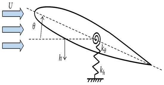
Figure 5. Schematic of an airfoil going through model convergence flutter.
Energy harvesters rely on crossflow flutter. The genuine fluttering leaves of a tree subjected to background fluxes inspired this piece. Li and Lipson [97] proposed a device consisting of a polyvinylidene fluoride or polyvinylidene difluoride stock, a plastic pivot, and a three-dimensional polymer “leaf”. The vertical and the horizontal stalk leaf were examined as two alternative layouts with various stalk axis orientations. The highest power density of 615 W was attained with a linked dual-membrane stock of 72 × 16 × 0.41 mm at 8 m/s on a 5 M power, while the highest power density of 2036 W/m3 was attained at 7 m/s on a 30 M force, using a unimorph-limited stem measuring 41 × 8 × 0.205 mm. Like the airfoil-based piezo aeroelastic energy harvester, the upright stalk bends as the leaf experiences paired twisting and torsional movements around the joint, resulting in modal convergence flutter. Piezoelectric materials like PVDF and their copolymers are significant and promising. However, their applications are restricted because of the much-decreased piezoelectricity. As a result, several initiatives to enhance piezoelectricity have been made, broadening the range of applications for it. Other preparation techniques include electrospinning, hot pressing, and solution casting. Processes such as stretching, adding fillers, heat treatment, poling, and nanofiller alignment by electric field/magnetic field have been developed, and the impact of the parameters has been examined to enhance the development of piezoelectric β-phase and the α-to-β phase transition. However, since it is still unclear how crystallinity arises, further research is required [98]. Different leaf shapes, leaf areas, short, long, and narrow-short stalk scales, monolayer, adherent dual-layer, and air gaps dual-layer PVDF arrangements were assessed and contrasted. The leaf’s equilateral triangle, square, and circular forms showed equivalent and maximum power, and the cut-in wind speed rose with the performance of the area of the leaf [99]. It has a parallel-flow asymmetric structure in which a torsional motion of the stalk around axis x was generated by the distance between the stalk and leaf axes. It is an energy extractor dependent on modal convergence flutter; however, because of Li and Lipson’s and Li’s constructs’ similarities, this part of the crossflow flutter contains its recommendations. Because the PVDF functioned in part of the d32 mode, wherein has a less piezoelectric transformation rate, it was determined that electrical d32 power from bending in a linear flow arrangement served solely as an auxiliary small-value gain as a result of folding. Although substantially less than a crossflow equivalent harvester, the production was comparable to a parallel-flow flapping-leaf harvester. De Marqui Jr. et al. also conducted studies about energy gathering from crossflow flutter [100]. For divided electrodes, torsional movements of the linked modes became very considerable, which was related with enhanced broadband productivity and greater flutter speed.
Hobeck et al. proposed another study on a novel type of flutter called a “dual-cantilever flutter”. Two cantilevers of 14.6 × 2.54 × 0.0254 cm3 were exposed to wind flow to experience the large amplitude and persistent vibration in the experimental setup of a wind tunnel. The highest power of 0.967 mW was obtained at 13 m/s. If the distance is small, between 0.25 cm and 1 cm, the cantilever produces enough power in the range of 3 m/s to 15 m/s. This determined that the “dual-cantilever flutter” is responsible for strong energy-scavenging methods for nonlinear flowing fluid [101].
Movement-induced excitation (MIE) is an immersed-shape self-excited flutter followed by twisting fragility at resonance, as shown in Figure 6. Negative damping and structural deformation through divergence occur at critical flutter speed. The seminal work demonstrates that self-generated MIE flutter and self-supported flutter. The seminal work was further illustrated in [102,103]. Critical flutter speed, the relation of flutter frequency, and a two-dimensional complaint beam in viscous flow were explained based on scaling laws, as shown below in the equation.
where ω is flutter frequency, Uc is the critical flutter speed, ρf is the density of the fluid, and ρs is the density of the beam. Similarly, Uc is the flow speed, h is the thickness of the beam, L is the beam length, and Y is the elastic modulus of the beam. Recently, experimental verification on scalable rules for rectangular, tri-directional beams was followed in [104].
where µ is the mass ratio, the above Equation (1) shows that the fraction of the non-dimensional weight is enormous. For an adequately minor mass ratio, dense effect and added mass are responsible for controlling the beam flutter motions compared to the estimated model displacement [105].
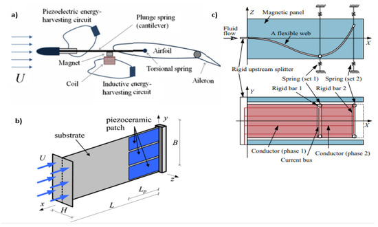
Figure 6. (a) Airfoil-based hybrid harvester; (b) T-shaped harvester; (c) electric current induction having a magnetic field in the flutter mill.
2.3. Vortex Induces Vibrations
Vortex-induced vibration (VIV) was priorly investigated in water flow rather than wind flow. When bluff bodies are subjected to an external force resulting in periodic abnormalities in the flow, vortex-induced vibration (VIV) emerges. The oscillations in the underwater cylinder are an excellent illustration of vortex-induced vibration. Because of its considerable curvature, this limit layer might segregate from the body at numerous locations. The pressure distribution along the surface is then changed by the generation of vortices [106]. Akaydin et al. [107] suggested a novel self-excited vortex-induced vibrational energy harvester to boost output power. Unlike in earlier occurrences, PZT was used to cover the end area of the cylinder, which was an aluminum cantilever’s free end connected. The aeroelastic efficiency was raised from 0.032% to 2.8% compared to the prior design. The finding was that the altered arrangement of the cylinder connection to the cantilever end and the substitution of PZT for PVDF considerably improved the power extraction. Due to vortex shedding, regular oscillations are generated in the path perpendicular to the flowing wind.
Weinstein et al. [108] developed an energy scavenger with tunable abilities for resonance to overcome the short operating range of VIV-based harvesters and presented a resonance-tuning-capable energy harvester. An aerodynamic fin was used to affix the piezoelectric cantilever to the head of a cylinder body. The resonant frequencies of the harvester might be fine-tuned by directly altering the mass locations. Weinstein et al. [108] proposed an energy-harvesting device ranging from 2 to 5 m/s. Their research was centered on the means of a piezoelectric beam affixed to the tip of a cylinder to capture energy from the VIV phenomena. Gao et al. reported a spherical prolongation to a piezoelectric cantilever (PEC) is used in a wind-energy collecting device. This model was constructed to generate electricity from VIV using a nonlinear distributed 192-parameter model, confirmed by the experimental data of Akaydin et al. Using a flexible piezoelectric beam, Goushcha et al. [109] collected the vibration energy based on the VIV. The topic of fluid flow energy extraction through the VIV of a circular cylinder in a dual-mass configuration was examined by Xu-Xu et al. [110]. Wang with his colleagues [111,112,113] created energy harvesters in the shape of a flow path, which they claimed were operated by a bluff body in the stream producing a vortex and shedding it. The diaphragm is attached to a piezoelectric patch or a magnet and coil for energy transmission. The effects of different bluff body shapes on wind harvesters were studied by Tam Nguyen et al. [114]. A 0.2 mm broad polydimethylsiloxane (PDMS) diaphragm was implanted in the prototype, and a PVDF sheet was bonded up to the flow network’s peak. The prototype measured an average power of 0.59 nW and a 14 mV open-circuit voltage at a wind velocity of 20.7 m/s. Wang et al. [115] utilized computational fluid dynamics modeling to highlight the importance of establishing the area of synchronization for VIV energy harvesting. Lately, the so-called vortex bladeless wind generator has been used in conjunction with VIV to capture wind energy on a big scale.
3. Galloping
Various investigations have proven the likelihood of extracting meaningful energy from the surrounding flow for the significant galloping vibration. The studies of mainly transverse and torsional energy collection during galloping are discussed. The aeroelastic instability phenomena of transverse galloping have only recently been used to get vibrations inside the structure for energy gathering. Galloping, in comparison to VIV, has the characteristics of enormous oscillation amplitude and the capability to oscillate in an unbounded range of wind speeds, which is desirable for energy harnessing [116]. Several research studies have shown transverse galloping energy extraction’s analytical and theoretical feasibility. Barrero-Gil et al. published analytical research to demonstrate the feasibility of cross-country galloping as an energy source. Using a 1DOF model, theoretically, Barrero-Gil et al. looked at the possibility of using galloping to generate energy. There was no particular type of energy harvesting suggested. The aerodynamic force was calculated using a cubic polynomial depending on the quasi-steady hypothesis. Theoretically, a very effective bluff body was determined to have a higher A1 aerodynamic coefficient and A3’s small significance level. The mass-damper parameter must be set to a minimal value for the mechanical damping [117].
Rather than utilizing a polynomial fitting, Sorribes-Palmer and Sanz-Andres [118] extend the research by accumulating the aerodynamics curvature parameter straight-forwardly by investigation records. Sirohi and Mahadik [119] presented a galloping energy harvester with two 161 × 38 × 0.635 mm3 cantilever beams and a prism 251 mm in length linked to the outer end and a 40 mm symmetrical triangular cross-section in every boundary. Directly acquiring from the experiment has eliminated the difficulties involved with polynomial fitting, such as incorrect dynamic reactions caused by erroneous polynomials. Sirohi and Mahadik [120] devised alternative galloping with an energy harvester, such as a D-shaped cross-section coupled to the composite piezoelectric beam. The tip body has a diameter of 30 mm and a length of 235 mm, while the cantilever has a volume of 90 38 0.635 mm3. An axial fan was used to create the wind flow, which had a highly turbulent profile. With a 10.5 mph wind velocity, the power density of 1.14 mW was produced.
Abdelkefi et al. [121,122] examined the topic with an energy harvester of a galloping square cylinder in a theoretical study. They discovered that when the load resistance grew, the commencement of galloping and output electrical power improved, but the displacement was reduced. An ideal load for higher Reynolds provided maximum power output, the maximum beginning of galloping, and minimizing distance simultaneously. According to Yang et al. [123], and Daqaq [124], once all energy harvesters are configured effectively, a bluff body with a squared section generally outperforms D-shaped and equilateral three-sided objects at high wind speeds. Using the Weibull probability density function, wind data were fitted, and Bibo and Daqaq [124,125,126] included actual wind-data figures in the results of energy harvesters that are in motion (PDF). Vicente-Ludlam et al. [127] discovered that by adjusting the output tolerance to loads in the appropriate adjustable, the power and efficiency for each wind-velocity generation productivity might be maintained throughout a broader range of wind speeds, as shown in Figure 7. Putting an impact bump stop onto a galloping harvester was discovered to extend its durability significantly during electromagnetic energy collection by a dual-mass galloping.
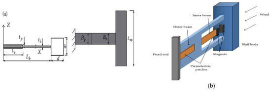
Figure 7. (a) Schematic of galloping with an energy harvester square bluff body; (b) at low wind speed, power enhancement through 2DOF piezoelectric galloping energy harvester [128].
Figure 8 below shows that when the speed of flow increases from the critical value, transverse fluctuation becomes the cause to interrupt the bluff body exposed through the airflow, and this phenomenon is known as galloping. There are twin galloping bluff bodies in the wake form of PEH; one is connected to the loose at the beam’s tip, and the other is attached in its front. A primary rule for the front bluff body depends on the certainty that variations are produced in the spacing distances [129,130,131]. Much research has been taking place to investigate the impact of various factors on galloping manufacturing [132,133].
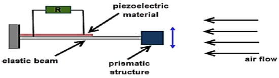
Figure 8. Example of PEH-based Galloping [134].
All the methods and techniques of energy harvesting from wind are described in Table 1 below:
Table 1. Piezoelectric Devices in Wind Flow.
| Windmill and Wind Turbine Energy Harvesting Devices | |||||||||
| Sr No. | Device | Transducer Type | Power Density (mW/mm3) | Dimensions | Cut-In Wind Speed (m/s) | Cut-Out Wind Speed (m/s) | Wind Speed (m/s) | Relevant Information | References |
| 1. | Fan-type windmill | Piezoelectric bimorph | 0.01042 | 114 mm diameter × 60 mm width, 60 × 20 × 0.6 mm3 each beam | - | - | 4.47 | - | [134] |
| 2. | Vane-type vertical windmill | Piezoelectric bimorph | 7.38 × 10⁻⁶ | 96 × 107 × 66 mm3 generator, 178 mm vane diameter | - | - | 4.47 | - | [135] |
| 3. | Fan-type windmill | Piezomagnetic generator PZT-5A |
- | 31 mm diameter | 0.9 | - | 0.9 | - | [136] |
| 4. | Fan-type windmill using impact-induced resonance | Piezoelectric unimorph PZT ceramic |
- | 31 mm diameter | - | - | Not specified (fan with the speed of 200 RPM rotation) | - | [137] |
| 5. | Contactless windmill, Savonius turbine | Piezomagnetic generator | 1.9 × 10⁻⁷ | 165 × 165 × 229 mm3 | - | - | 4.02 |
|
[137] |
| 6. | Small-scale windmill and turbine | Piezoelectric material. Contact via mechanical stopper |
0.00267 | 5.08 × 11.6 × 7.62 cm3 | 2.1 | 6.2 | 5.4 | [138] | |
| Flutter Energy Harvesting Devices in Wind Flow | |||||||||
| Sr No. | Device | Transducer Type | Power Density (mW/mm3) | Wind Speed (m/s) |
Cut-In Wind Speed (Flutter speed) (m/s) | Cut-Out Wind Speed (m/s) | Dimensions | Relative Information | References |
| 1. | Rigid flap with revolute joint | Bimorph_ PZT | 6.3 × 10⁻⁵ | 7.9 | 2.6 | - | 283.7 × 136 × 0.9 mm3 | - | [138] |
| 2. | The piezoelectric film with plastic extension | Rectangular film PVDF |
0.0524 µW/mm3 | 2 | - | - | 22 × 13 × 0.2 mm3 | - | [138] |
| 3. | Piezoelectric grass | Bimorph | 0.0038 | 11.5 | - | - | Four 101.6 × 25.4 × 0.406 mm3 beams | - | [139] |
| 4. | Inverted flag | Piezoelectric membrane | 0.00347 | 9 | - | - | 60 × 120 × 0.2 mm3 | - | [139] |
| 5. | Modal convergence flutter with flat plate | Piezoelectric | Stiff host: 6.078 Compliant host: 4.696 |
Stiff host: 26 Compliant host: 25 |
Stiff host: 17.3 Compliant host: 15.2 |
Stiff host: 29 Compliant host: 29 |
Flat plate tip: span 6 cm, chord 3 cm, thickness 0.79 mm. Cantilever: 7.6 × 2.5 × 0.0381 cm3 |
|
[139] |
| 6. | Dual cantilever flutter | Piezoelectric | 0.845 | 13 approx. | 3 approx. | - | Two identical cantilevers: 14.6 × 2.54 × 0.0254 cm3 | Efficient power generation with high operational wind speed | [140] |
| Micro Scale Piezoelectric Wind Energy Harvesters | |||||||||
| Sr No. | Transducer | Mechanical Mechanism | Size (mm) | Peak Power | Voltage | Wind Speed(m/s) | Power Coefficient Cp (%) | Normalized Power Density (μW × s/ (mm3 × m)) | References |
| 1. | Piezoelectric | Aeroelastic | 2 × 1.65 × 0.005 | 34 nW | 25 mW | 5.2 | 0.012 | 0.39 | [140] |
| 2. | Piezoelectric | Rotational | 47 × 20 × 0.5 | 613 µW | 13 V | 200 r/min | - | - | [141] |
| 3. | Piezoelectric | Aeroelastic | 75 × 20 × 0.004 | 0.98 µW | 1.2 V | 3.9 | 0.002 | 0.041 | [141] |
| 4. | Piezoelectric | Rotational | ϕ = 53 | 7.5 mW | 5 V | 4.47 | 6.32 | - | [142] |
| 5. | Piezoelectric | Aeroelastic | 23 × 4 × 0.130 | 0.64 µW | 1.6 V | 15 | 3.4 × 10⁻⁴ | 0.004 | [143] |
| 6. | Piezoelectric | Aeroelastic | 58 × 10 × 0.202 | 30 µW | 4.3 V | 5 | 0.06 | 0.05 | [144] |
| 7. | Piezoelectric | Aeroelastic | 3 × 8 × 0.035 | 2.27 µW | 965 mV | 16.3 | 0.004 | 0.17 | [144] |
| 8. | Piezoelectric | Aeroelastic | 69 × 37 × 0.24 | 3.3 V | 1 mW | 2 | 8.1 | 0.81 | [145] |
| Macro Scale Piezoelectric Wind Energy Harvesters | |||||||||
| Sr No. | Transducer | Mechanical Mechanism |
Size (mm) | Voltage | Power Peak | Wind Speed(m/s) | Power Co-efficient Cp (%) | Normalized Power Density (μW × s/ (mm3 × m)) | References |
| 1. | Piezoelectric | Aeroelastic | 76.7 × 12.7 × 2.2 | 8.8 V | 155 µW | 6.7 | 0.09 | 0.01 | [145] |
| 2. | Piezoelectric | Rotational | ϕ = 80, t = 170 | 80 mV | 2 µW | 14 | 2.4 × 10⁻⁵ | 1.7 × 10⁻⁷ | [146] |
| 3. | PZ | Aeroelastic | 90 × 10 × 0.6 | 12 V | 145 µW | 3.5 | 0.63 | 0.08 | [147] |
| 4. | PZ | Rotational | 325 × 36.2 × 0.267 | 30 V | 1.14 mW | 4.96 | 0.15 | 0.077 | [148] |
Many bluff body designs were studied to increase the wake flow’s pressure from the vortex. Researchers conducted computational fluid dynamics (CFD) models to understand better vortex formation and how it affects the harvester efficiency. When a half-reversal velocity occurs when the river passes, the bluff body velocity difference occurs because of fluid pulls causing the vortex to form. Viscous shearing between the solid object and the fluid layer generates friction drag. Maximizing the velocity ratio, k, generates an inner kinetic energy reduction throughout the bluff body’s longitudinal distance.
As a result, the length is reduced by using a bluff body with a cuboid form. Because of the steep flow detachment point, the primary edge might move toward the inflow area, increasing vortex pressure. According to CFD simulation results, the vortex pressure in the wake of a cuboid-shaped bluff body reaches 84 Pa at 2 m/s air flow (Figure 9c). This is roughly four times larger than a cylinder-shaped bluff body, as seen in Figure 9a. The simulation’s outcomes indicate the shedding of an additional vortex that flows following the primary vortex (Figure 9a,c). It was supposed to be more dampening, which would result in poor harvester performance [148]. Table 2 shortlists all the techniques that help in energy harvesting in wind flows from piezoelectric devices.
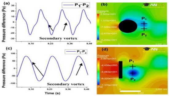
Figure 9. (a) Comparison of vortex pressure in the cylindrical bluff body wake; and (b) associated pressure difference; (c) when a vortex is present in the cubical bluff body wake; and (d) associated pressure difference [148].
Table 2. Techniques of PEH in Wind Flow.
| Ref. | Technique | Brief Title | Highlights | Authors |
|---|---|---|---|---|
| [149] | VIV | Flow-induced based on PEH | Utilizing a one-dimensional approach to investigate the function of an adaptable piezoelectric cylinder, the produced power | Xie et al. |
| [150] | VIV | Tree-simulated piezoelectric | Four cylindrical linear arrays connected to piezoelectric actuator were tested in the wind. | Hobbs and Hu. |
| [151] | VIV | Designing of fluid K.E harvesters | The harvester was optimized using a cuboid-shaped bluff body and a 1 μ W output power. | Wen et al. |
| [151] | VIV | Air conditioners containing piezoelectric | A piezoelectric energy-harvesting system was offered based on VIV with a fin for use in turbulent airflow. | Weinstein et al. |
| [151] | VIV | Cylindrical extension on piezoelectric cantilevers | A wind-driven cylinder with a piezoelectric beam attached to the edge has been described as an energy harvester. | Gao et al. |
| [151] | VIV | Piezoelectric analysis with non-uniformity | Investigating a piezoelectric cantilever ray connected to the radial cylinder subjected to nonuniform distribution structure. | Dai et al. |
| [152] | VIV | Fluidic energy with flexible beam | By the usage of flexible beam piezoelectric harvesting vibrational energy construct of VIV. | Dunnmon et al. |
| [152] | VIV | Circular cylinder of VIV | Enhancing the efficiency of dual-mass development compromises on a circular cylinder. | Dunnmon et al. |
| [152] | Flapping | Oscillations in the aeroelastic limit cycle | In a wind s velocity of 27 m.s-1, piezoelectric plates were put on a floppy sheet. | Dunnmon et al. |
| [153] | Flapping | Cross flow fluttering by the usage of wind harvesters | Wind energy was turned into electrical energy by a swinging leaf dependent on aeroelastic fluttering. | Li et al. |
| [154] | TIV | TIV comprising of artificial piezoelectric grass | TIV was studied using a piezoelectric grass and a variable structure model. | Hobeck and Inman |
| [154] | TIV | TIV with a mathematical framework | TIV force of a unimorph cantilever was given by scattered a computational model. | Hobeck and Inman |
| [155] | TIV | Micromachined piezoelectric harvesting | 2W of energy is produced by a MEMS piezoelectric and a Helmholtz oscillator that includes a packed harvester. | Matova et al. |
| [156] | TIV | Unsteady flows for piezoelectric | Flexible piezoelectric cantilever beams were positioned in turbulent boundary layers to generate 0.06 W. | Akaydin et al. |
| [156] | TIV | Wake of a cylinder | Applying piezoelectric beams, the greater Reynolds values were used to study the effects of radial cylinders. | Akaydin et al. |
| [157] | TIV | Turbulent boundary layers in piezoelectric transducers | In a turbulent boundary layer, several piezoelectric beams were examined. | Goushcha |
| [158] | FIV | In axial flows, the performance of piezoelectric flags | A nonlinear variant of the FIV was proposed for a moving plate in an axial flow using piezoelectric patches. | Michelin and Doare. |
| [159] | FIV | Piezoelectric cantilever of T-shaped | Depending on the aeroelastic oscillation, a T-shaped piezoelectric cantilever was demonstrated. | Kwo |
| [160,161] | FIV | Single piezoelectric generator of aerodynamic | A piezo-aeroelastic energy harvesting system that depends on flutter was studied. | Bibo and Daqaq. |
| [162] | FIV | Aeroelasticity nonlinearity | Piezoelectric transmission and airfoil form nonlinear investigation methods. | Dowell et al. |
| [163] | FIV | Piezoaeroelastics analysis | To prevent pressurized collapse of piezo-aeroelastic harvesters, a nonlinear model was investigated. | Abdelkefi et al. |
| [164] | Galloping | Low-power sensors containing wind harvesters | In an air velocity of 11.6 miles per hour, a galloping-based piezoelectric yielded a captured energy of moreover 50 mW. | Sirohi and Mahadi. |
This entry is adapted from the peer-reviewed paper 10.3390/en15197424
This entry is offline, you can click here to edit this entry!