Your browser does not fully support modern features. Please upgrade for a smoother experience.
Please note this is an old version of this entry, which may differ significantly from the current revision.
In this manuscript, an effort is made to comprehensively deliberate/review the issues with the emergence of a high-voltage and high-power SST and related state-of-the-art investigations, mainly focusing on high-voltage power devices, high-power and high-frequency transformers, AC-AC topologies, and the application of SSTs in distribution systems.
- SST
- AC-AC converter
- distribution transformer
- DC-DC converter
1. Introduction
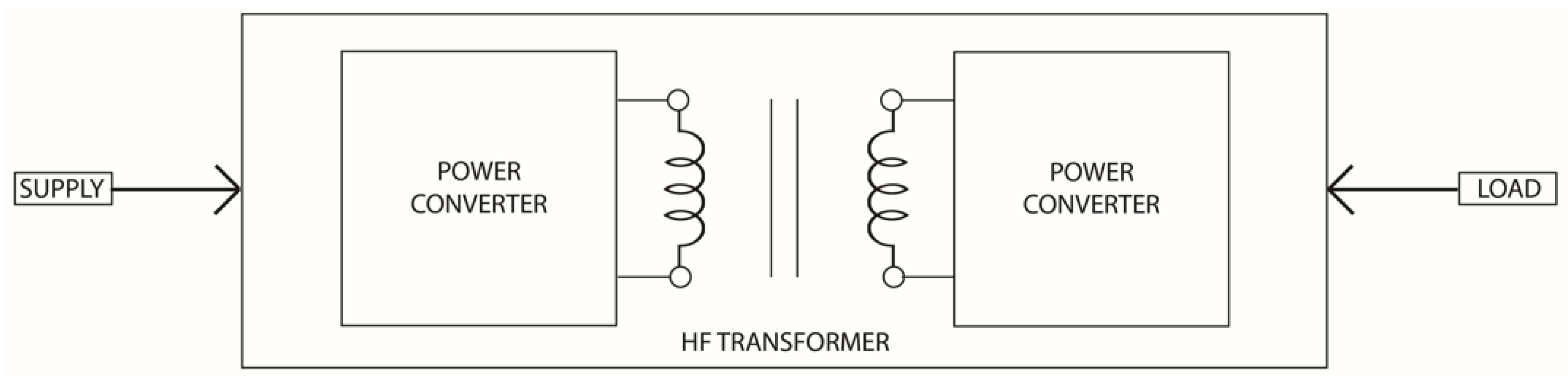
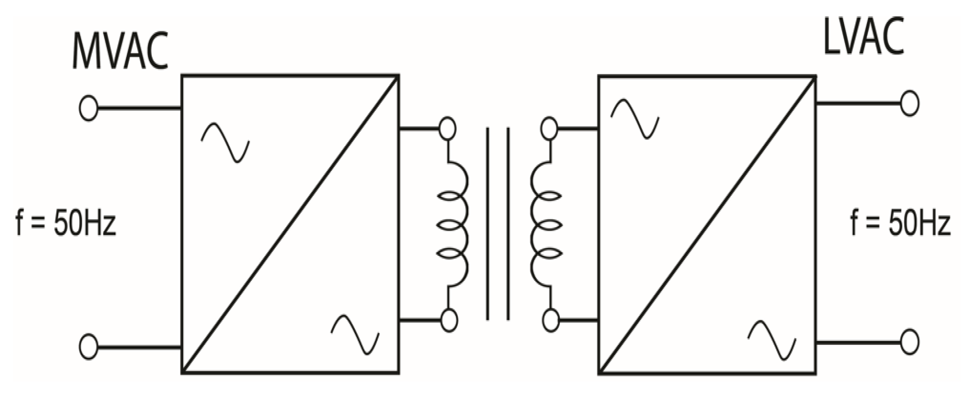
The Solid State Transformer (SST) is now considered to be the most suitable and appropriate conversion device to replace the traditional prevailing transformer. In this device, the weight/volume savings, extensive efficiency enhancement and above all, the cost economization are taken to be the hallmarks. Several topologies, arrangements and uses of SST technology have been, and continue to be, anticipated and evaluated [1]. Conceptually, Figure 1 illustrates the basic concept diagram of the SST, which involves a combination of high-frequency transformer and power electronics components.
From a practical aspect, the SST configuration comprises of three main stages (i.e., a rectifier, isolation through the HF transformer and finally the DC-AC converter to reproduce line frequency AC). Figure 2 illustrates such an arrangement from a practical perspective.
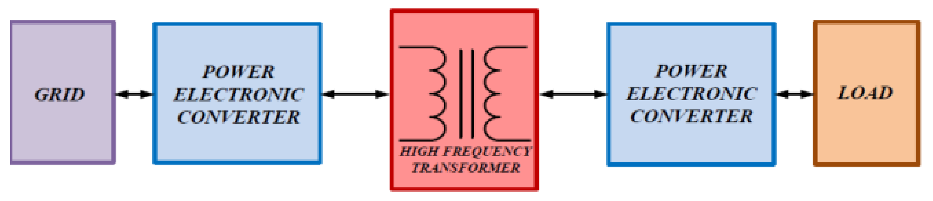
Figure 2. Practical Topology of SST [4].
The most promising and practical three-stage structure contributing to the anticipated solution is shown in Figure 3. This circuit contains low-voltage and medium-voltage DC buses and a completely decoupled arrangement between two AC sources with reactive power compensation capability.
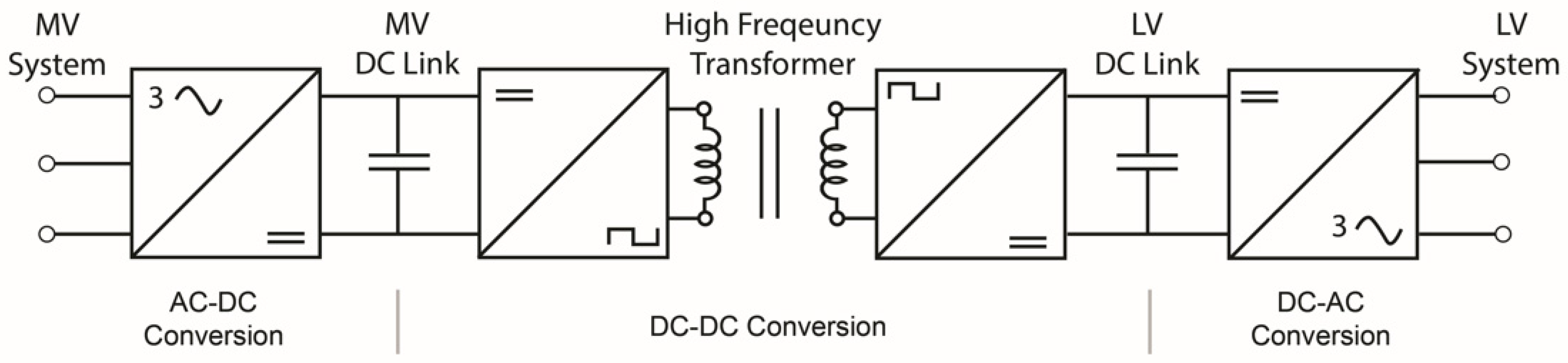
Figure 3. Elaborative Applied Topology of SST [5].
To date, the fabrication of SSTs is in the research and development phase. In fact, the invention of the SST comprises a practical semiconductor scheme, adopted to achieve a high power density at high frequencies, resulting in a reduction of size and cost. The weight and size may be up to three times smaller than that of the equivalent traditional transformer. Moreover, it is more environmentally responsible as no fluid/liquid dielectric is incorporated for cooling and other related purposes [6]. SSTs can be made operational/functional with a refined state-of-the-art communication interface incorporating elements such as smart metering, diagnostics and space control. SSTs are also considered for use in single-wire earth return transmission systems [7]. As the SST is the combination of a powered electronic circuit and a HF transformer, the voltage regulation, voltage dip/sag protection, fault segregation and DC output are some of its main features [8]. Consequently, SSTs will be used as energy routers/drives incorporating both AC and DC interfaces in impending distribution systems. The advantages of SST comprise their reduced weight, compact volume, active controllable devices, voltage sag and outage compensation, direct regulation of voltage, isolation of fault, power factor correction, harmonic isolation, cost-effectiveness and environmental friendliness [9].
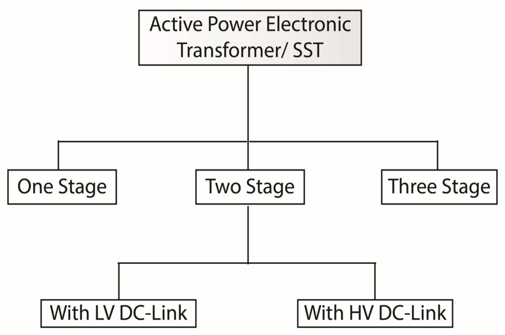
SSTs are not yet commercialized and are still in the exploration stage [10]. Many firms and research organizations/establishments are undertaking research in this area and are committed to testing prototypes to suit them in particular applications. It is estimated that the SST market will be commercialized in a year or so and exhibit a remarkable growth rate in the coming years [11]. The concept of SST was first presented by McMurray [12] in 1968; this introduction was generally based on solid state switches using high-frequency isolation. SSTs were noted in the National Science Foundation (NSF) Generation-III Engineering Research Centre (ERC) as “Future Electric Energy Delivery & Management (FREEDM) Systems” which came into existence in 2008 and again in 2010; the proposal of SSTs was acknowledged as one of the ten most promising technologies in the appraisal of the Massachusetts Institute of Technology (MIT) [13]. The selection of the most suitable topology for SST execution is the main challenge, which can be tackled by analyzing several of the existing latent, possible and promising topologies which can provide the unidirectional power course. In this scenario, a number of available topologies for SSTs (including a general AC-AC power converter) have been deliberated and studied [14]. Some of these topologies and configurations are not in support of the parameters of bi-directional power flow. Effort has been undertaken to categorize SST topologies and to earmark the most befitting one as per obvious and explicit needs [15]. Figure 4 illustrates the general classification of SST topologies [16][17].
1.1. Single-Stage SST
There are several single-stage topologies (direct AC-AC conversion) which facilitate a unidirectional power flow; however, the lack of a DC link is still taken as the major drawback of these topologies, which is evident in Figure 5. Here, the combination of storage elements and power flow improvement would definitely require additional devices/procedures, resulting in an increase in system complexity and size as well as cost of the overall system. Nevertheless, due to its simple and brief configuration, it currently does present a promising cost-efficient and lightweight solution [18][19].
1.2. Two-Stage SST
The direct current link of this design may not be considered viable for distributed energy storage (DES) as well as distributed energy resource (DER) integration, due to the high energy voltage and the absence of arrangement for isolation from the grid [19][20]; however, the fabrication under this arrangement may not be practically viable in SST applications. This arrangement also possesses two-stage conversions, where galvanic isolation along with a voltage step-down process is addressed in the DC-DC converter stage. In one of these two arrangements, a low voltage DC link does not exist. Figure 6 illustrates a two-stage SST topology [21].
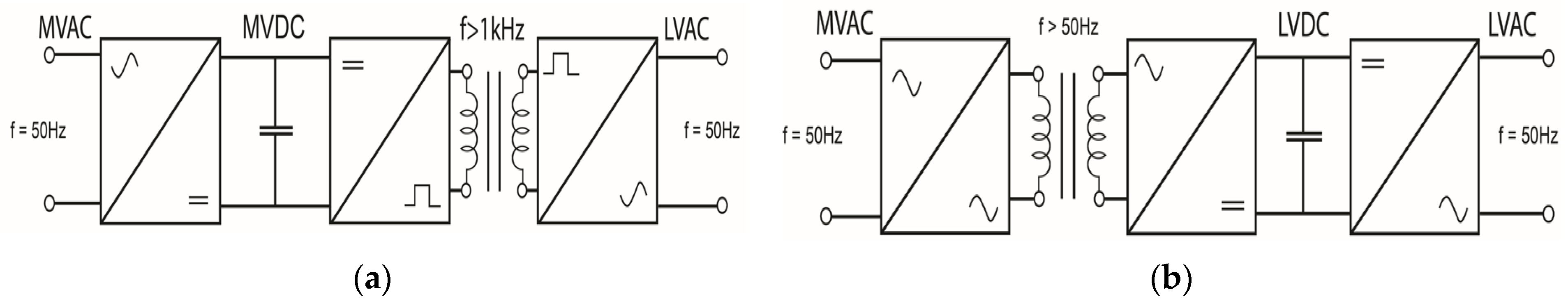
Figure 6. A Two-stage SST (a) with medium voltage direct current (MVDC) Link. (b) With LVDC Link [21].
1.3. Three-Stage SST
A three-stage structural design with two DC links, is the most workable, practical and realistic solution due to its high flexibility and control performance. It ensures numerous functions that are enviable when compared to SST functions. This configuration encompasses the conversion of AC voltage at the input to a corresponding DC voltage, resulting in a medium voltage direct current (MVDC) link. Then, this MVDC is processed to change into HF AC voltage, which is routed through to the medium-frequency transformer. At this stage, the voltage level is condensed, rectified once more to a low-voltage DC level and finally constitutes a low-voltage DC link. At a further stage, this obtained low-voltage direct current (LVDC) is transformed once more in order to achieve 50 Hz AC voltage. The diagrammatic representation of this topology with three distinct stages is illustrated in Figure 7. The MVDC is considered to be a viable one for renewable energy sources connected with SSTs [22].
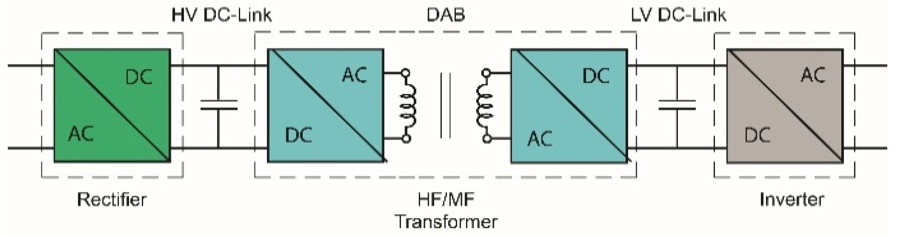
Figure 7. Three-stage SST topology [22].
2. Three Topologies and SST Applications
2.1. Solid State Transformer Architecture
The most suitable and appropriate configuration, competent enough to support additional/supplementary missions/functionalities as opposed to a regular transformer, was identified. These functionalities included: (1) on-demand reactive power support to the grid, (2) voltage regulation, (3) power quality and (4) the current limiting, restraining and provision of DC bus. The configurations considered were bi-directional, dictating a minimum requirement of substituting a regular existing transformer. A critical, influential and significant analysis of three main topologies for the implementation of a SST was deliberated, and the following conclusions were reached:
A single-stage SST topology is a configuration without a DC link, which restricts its operation of the integration of renewable energy sources, as well as energy storage devices. The deficiency of such a DC link exhibits no planning in terms of voltage regulation coupled with reactive power compensation [23]. Therefore, no arrangement existed for input power factor correction. In these circumstances a single-stage topology is not given due deliberation for the contestants of SST applications for future grid requirements [24][25][26].
A two-stage SST with a high HVDC link is considered to be least suitable arrangement, for the reason that it is lacking an isolation arrangement from the grid. Therefore such a topology does not comply with or conform to smart grid requirements. Moreover, this DC link is not in place for DES and DER. Furthermore, the necessity of the huge size of filters for eradicating large ripple currents is considered to be the foremost and key shortcoming for attaining the voltage regulation and henceforth, practically not possible in SST applications. The DC-AC converter part of such arrangement is a double phase inverter [27][28].
The most feasible, appealing and practical topology of the SST is a three-stage configuration (i.e., topology with high voltage (HV) as well as with low voltage (LV) DC links). These links are meant to enhance the ride-through competency of SSTs, thereby allowing the improvement of power quality at the input as well as output ends. This three-stage topology offers all the preferred SST functionalities, simplifying the control design. The LVDC link contributes to all of the anticipated SST functionalities, including the interfacing of distributed energy resource (DER) and distributed energy storage (DES) . The structural design of this topology comprises a distinct rectifier, an isolated DC-DC converter (i.e., a high frequency inverter, high frequency medium power transformer and a rectifier) and DC-AC converter stages. This topology offers tremendous advantages over the other topologies, including high flexibility and control performance, and it is weighed as the most workable, practical and realistic solution [29][30][31][32].
2.2. Transformer-Isolated DC-DC Converter
The transformer-isolated DC-DC converter as an entity and the SST as a scheme; both of these arrangements make use of HF inverter at the input side of the MPHF transformer in order to produce AC voltage. Transformer-isolated converters are incorporated primarily for the establishment of galvanic isolation, to enhance safety, to raise noise immunity and to avoid the transmission of voltage transients to the output. With fragmentary technological progression in power electronics, exploration in this arena is very vigorous and rationalized, and numerous research manuscripts are circulated [33][34][35][36].
Power conversion using high-frequency inverters are achieving improved consideration in scheming high-frequency power distribution arrangements. Researchers (academic/industrial) and investigators are carrying out extensive research on the design of HF inverters in different configurations/topologies. In a bridge arrangement, the vital structures proposed are the full bridge (FB) and half bridge (HB) inverter in step down mode and step up mode; performance concerning efficiency and total harmonic distortion (THD) were deliberated through experimental results [37][38].
2.3. High Frequency DC-AC Inverter
The literature survey emphasizes the importance of HB configuration in terms of output voltage, number of bridges, number of switches, etc. The advantages of the HB arrangement are as follows: (1) the output voltage is halved compared to the full bridge (FB) voltage requirement (i.e., step down), (2) the number of bridges required is halved as compared to the FB topology (3) the sufficient simplification of a power scheme layout, (4) the reduction in the complexity of control and protection circuitry, coupled with the reduced converter price [39][40][41][42][43].
A number of researchers have worked on the design of inverter in the FB configuration, whereas very few have based their studies on HB topology [44][45][46].
2.4. Embryonic Development—HFHP Isolated DC-DC Module
A transformer-isolated DC-DC converter stage in high frequency perspective is considered to be the most significant and vital element of the SST system [47][48][49]. Conventionally, the frequently used practical devices in practice are the high voltage IGBTs, based upon three-level NPC topology; however, the 1.7 kV IGBT with low cost can also be incorporated for certain applications [50][51][52][53]. With the emergence of wide-band gap devices, the DC-DC stage working frequency is escalating, even up to 50 kHz. The DAB converter undergoes the most frequently used topology with high performance [54][55][56][57].
The LLC unregulated resonant converter (DCX) is already in practice by ABB. System efficiency has improved gradually. From the magnetic aspect, the nano-crystalline and MnZn ferrite are the most tremendous and frequently used core materials, because of their enlarged working frequency [58][59][60]. The transformer structures most commonly adopted are still the UU core shape and EE core shape [61][62][63]. Litz wire is used in almost all the transformer windings, in order to reduce the frequency current conduction loss. Most transformers use dry-type insulation; whereas ABB is already switching to oil-immersed insulation owing to its 15 kV medium voltage application [64][65][66][67].
3. Transformer as Galvanic Isolator of the DAB/DHB
In comparison to conventional transformers, the SST incorporates power electronic converters using a HF transformer. Power switches such as MOSFET, IGBT, etc., are widely used [68][69][70][71]. The HF transformer plays a vital role in design and functionality. It deals mainly with the efficiency aspect, depending on the operating condition, and wire/core selection [72]. Although the high operating frequency contributes to the compactness and density of the transformer, there are many more limitations/restrictions which must be taken into consideration, such as insulation, power loss and costs [73][74][75][76].
There are two kinds of losses which contribute to total transformer losses; these include the core losses (no load loss) and the winding/copper losses (load loss) [77][78][79][80]. HF transformers in SSTs primarily cater to the performance and overall efficiency; that is why the selection of suitable materials, along with the optimization of the design, is imperative in meeting all of the requirements for the operating conditions [79][80][81]. Various types of core material characteristics are also momentarily abridged [82][83][84][85]:
-
Nano-crystalline (FT-3M): Possesses saturation flux density, Bmax,1.23 (T), Curie temperature Tc 570 (°C) and maximum operation temperature.150 (°C).
-
Ferrite (3F3): Possesses saturation flux density, Bmax, 0.45 (T), Curie temperature Tc 200 (°C) and maximum operation temperature. 120 (°C).
-
Super-alloy: Possesses saturation flux density, Bmax 0.79~0.87 (T), Curie temperature Tc 430 (°C) and maximum operation temperature. 125 (°C).
-
Amorphous (2605SA): Possesses saturation flux density, Bmax 1.57(T), Curie temperature Tc 392 (°C) and maximum operation temperature. 150 (°C).
4. Applications of SST and DC-DC Converter
Transformers are installed at the ends of generating stations. Distribution substations are used in the transportation of electric power at long distances in order to lower the voltages required by homes, businesses and other utilities (i.e., with the key function of reducing the high voltages) [83][84][85][86]. Currently existing transformers operate only in one direction, and some of the services provided by the SST structure comprise the safety of load and the power system from power supply disorders, the sag compensations, the load transients and harmonic regulations, the unity input power factor (PF) in reactive load, the sinusoidal input current in the case of non-linear loads, the safety against output short circuit, the operation on distributed voltage level, the amalgamation of energy storage and the medium frequency isolation [87][88][89][90][91][92][93][94].
To implement this technology in a befitting manner, tremendous efforts have been carried out to design and structure the SST and observe its impending application in the distribution system [95][96][97].
The applications and uses of the SST in certain spheres are much more striking and appealing [98]. Some examples of these applications include: (1) The locomotive and related traction system as a significant and momentous weight reduction mechanism; this results in the enhancement of efficiency and a reduction in EMC/harmonics (2) The desired energy generation as a means for cheaper offshore platforms. (3) Smart grid applications for the dynamic adjustment of energy distribution. (4) Integration with other energy systems. (5) Applications between generation sources and load/distribution grids to attain a unity power factor from energy transportation. (6) The controlling of active power between two distribution grids and action as a reactive power compensator for both grids. (7) Linkage between the MV and LV grid to control the amount of reactive power flow. (8) Action as an interface for distributed generation and smart grids [99][100][101][102]. Diverse applications/usages lead to different requirements.
In a high-power conversion scenario, the DAB DC-DC converter is found to be the most viable and promising elucidation, which is in-fact a galvanically isolated DC-DC conversion device [103][104]. The various characteristics and applications of the isolated DC-DC converter include: (1) Being a modular, symmetric structure with high power density for multiport operations. (2) Being extensively used to interface with the distribution grid on a population level (i.e., with the 220 VAC, 50/60 Hz utility grid). (3) Energy/power storage schemes. (4) Fuel cells and interfaces for multiple renewable energy sources (e.g., photovoltaic (PV) modules). (5) Chargers for plug-in hybrid electric vehicles (PHEVs)/battery electric vehicles (BEVs). (6) Bi-directional conversion capability. which supports the growth of smart interactive power NWs, where energy arrangements compose an energetic role for the provision of numerous kinds of support to the grid (e.g., vehicle-to-grid (V2G) perceptions). (7) AC microgrids and inhabited DC distribution systems (DC nano-grids) [105][106][107][108][109]. Solar power technologies, wind power for homes/businesses, etc., are the aspects for renewable energy [110].
This entry is adapted from the peer-reviewed paper 10.3390/sym14102027
References
- Huber, J.E.; Kolar, J.W. Solid-State Transformers: On the Origins and Evolution of Key Concepts. IEEE Ind. Electron. Mag. 2016, 10, 19–28.
- Acikgoz, H.; Kececioglu, O.F.; Yildiz, C.; Gani, A.; Sekkeli, M. Performance analysis of electronic power transformer based on neuro-fuzzy controller. SpringerPlus 2016, 5, 1350.
- Heinemann, L.; Mauthe, G. The universal power electronics based distribution transformer, an unified approach. In Proceedings of the 2001 IEEE 32nd Annual Power Electronics Specialists Conference (IEEE Cat. No.01CH37230), Vancouver, BC, Canada, 17–21 June 2001; Volume 502, pp. 504–509.
- Roy, R.B.; Rokonuzzaman, M.; Hossam-E-Haider, M. Design and analysis of the power electronic transformer for power quality improvement. In Proceedings of the 2015 International Conference on Electrical Engineering and Information Communication Technology (ICEEICT), Dhaka, Bangladesh, 21–23 May 2015; pp. 1–5.
- Falcones, S.; Ayyanar, R.; Mao, X. A DC–DC Multiport-Converter-Based Solid-State Transformer Integrating Distributed Generation and Storage. IEEE Trans. Power Electron. 2013, 28, 2192–2203.
- Ahmed, K.; Yahaya, N.Z.; Asirvadam, V.S.; Ibrahim, O. Modeling and Simulation of Power Electronic Distribution Transformer Based on a Three Level Converter. Appl. Mech. Mater. 2015, 785, 151–155.
- Merwe, J.W.V.d.; Mouton, H.D.T. The solid-state transformer concept: A new era in power distribution. In Proceedings of the AFRICON 2009, Nairobi, Kenya, 23–25 September 2009; pp. 1–6.
- Zhao, T.; Wang, G.; Bhattacharya, S.; Huang, A.Q. Voltage and Power Balance Control for a Cascaded H-Bridge Converter-Based Solid-State Transformer. IEEE Trans. Power Electron. 2013, 28, 1523–1532.
- Shadfar, H.; Ghorbani Pashakolaei, M.; Akbari Foroud, A. Solid-state transformers: An overview of the concept, topology, and its applications in the smart grid. Int. Trans. Electr. Energy Syst. 2021, 31, e12996.
- Mcmurray, W. Power Converter Circuits Having A High Frequency Link. U.S. Patent No. 3,517,300, 23 June 1970.
- Pratik Mandon, A.P. Eswara Prasad. Solid State Transformer (SST) Market Outlook—2028. Available online: https://www.alliedmarketresearch.com/solid-state-transformer-market (accessed on 22 August 2022).
- Davis, S. Are Solid-State Transformers Ready for Prime Time? Available online: https://www.electronicdesign.com/technologies/alternative-energy/article/21199414/are-solidstate-transformers-ready-for-prime-time (accessed on 16 August 2022).
- Mumuluh, R.N. Design Considerations for a High Power, Medium Frequency Transformer for a DC-DC Converter Stage of a Solid State Transformer. Doctor’s Dissertation, University College Dublin, Dublin, Ireland, 2016.
- Hengsi, Q.; Kimball, J.W. Ac-ac dual active bridge converter for solid state transformer. In Proceedings of the 2009 IEEE Energy Conversion Congress and Exposition, San Jose, CA, USA, 20–24 September 2009; pp. 3039–3044.
- She, X.; Huang, A.Q.; Wang, G. 3-D Space Modulation with Voltage Balancing Capability for a Cascaded Seven-Level Converter in a Solid-State Transformer. IEEE Trans. Power Electron. 2011, 26, 3778–3789.
- Beldjajev, V. Research and Development of the New Topologies for the Isolation Stage of the Power Electronic Transformer; Tallinn University of Technology: Tallinn, Estonia, 2013.
- Falcones, S.; Mao, X.; Ayyanar, R. Topology comparison for Solid State Transformer implementation. In Proceedings of the IEEE PES General Meeting, Minneapolis, MN, USA, 25–29 July 2010; pp. 1–8.
- Shojaei, A.; Joós, G. A topology for three-stage Solid State Transformer. In Proceedings of the 2013 IEEE Power & Energy Society General Meeting, Vancouver, BC, Canada, 21–25 July 2013; pp. 1–5.
- Dheeraj Reddy, D.S.K.S. Design of Solid State Transformer. Int. J. Adv. Res. Electr. Electron. Instrum. Eng. 2015, 357–364.
- Sharun John, B.N.R. Active power electronic transformer a standard building block for smart grid. In Proceedings of the International Journal of Electrical Engineering & Technology (IJEET), Ernakulam, India, 30–31 December 2014; pp. 178–184.
- She, X.; Yu, X.; Wang, F.; Huang, A.Q. Design and demonstration of a 3.6kV 2013;120V/10KVA solid state transformer for smart grid application. In Proceedings of the 2014 IEEE Applied Power Electronics Conference and Exposition—APEC 2014, Fort Worth, TX, USA, 16–20 March 2014; pp. 3429–3436.
- Wang, G.; Huang, X.; Wang, J.; Zhao, T.; Bhattacharya, S.; Huang, A.Q. Comparisons of 6.5kV 25A Si IGBT and 10-kV SiC MOSFET in Solid-State Transformer application. In Proceedings of the 2010 IEEE Energy Conversion Congress and Exposition, Atlanta, GA, USA, 12–16 September 2010; pp. 100–104.
- Dewangan, R.; Potdar, R. Comparative Analysis of Multilevel Inverter and Its PWM Schemes. Int. J. Dig. Appl. Contemp. Res. 2015, 4. Available online: https://ijdacr.com/uploads/papers/40300-15-005.pdf (accessed on 23 July 2022).
- Bharati Mishra, S.S.K. Design of an improved PWM inverter using PI controller. Int. J. Multidiscip. Res. Dev. 2016, 3, 92–95.
- Kalavalli, C.; Paveethra, S.; Murugesan, S.; Ali, N.; Venkatesh, V. Design And Implementation of High Efficiency H6 PV Inverter with Dual Axis Tracking. Int. J. Sci. Technol. Res. 2020, 9, 4728.
- Hyun, J.; Jung, J.-H. Practical Design of Dual Active Bridge Converter as Isolated Bi-directional Power Interface for Solid State Transformer Applications. J. Electr. Eng. Technol. 2016, 11, 1265–1273.
- Harish Tata, P.M.S. A Literature Survey on Multilevel Inverter and its Parameter. Int. J. Eng. Technol. Appl. Sci. 2016, 2, 1–16.
- Raihani, A. Performance Evaluation for Different Levels Multilevel Inverters Application for Renewable Energy Resources. J. Eng. Technol. 2017, 6, 90–96.
- Akash Trivedi, S.; Rohan, A.; Mit, S.; Ankit, P. Design and Development of 3 Phase PWM Inverter. In Proceedings of the National Conference on Emerging Trends, Challenges & Opportunities in Power Sector, Ahmedabad, India, 3–4 March 2017; pp. 85–88.
- Gajowik, T. Review of multilevel converters for application in solid state transformers. Przegląd Elektrotechniczny 2017, 1, 3–7.
- PHANIKUMAR, A.B.; VALI, A.K. Renewable Energy Sources Based Single-Phase Seven Level Inverter Fed Induction Motor Drive. Int. J. Soc. Sci. Technol. 2017, 6, 1044–1049.
- Costa, L.F.; Buticchi, G.; Liserre, M. Optimum Design of a Multiple-Active-Bridge DC–DC Converter for Smart Transformer. IEEE Trans. Power Electron. 2018, 33, 10112–10121.
- Ji, Z.; Rao, R.; Wang, Q.; Li, D.; Sun, Y.; Wang, J.; Zhao, J. Soft-starting scheme for a DC solid-state transformer based on a modular multilevel converter. Energy Rep. 2021, 7, 378–387.
- Sathisha, K.; PintoPiusA, J. Comparison of two Different Approaches for Harmonic Analysis of Single Phase Inverter. Int. J. Innov. Res. Electr. Electron. Instrum. Control. Eng. 2017, 5, 1–6.
- Gao, Z.; Fan, H. A Modular Bi-Directional Power Electronic Transformer. J. Power Electron. 2016, 16, 399–413.
- Chakraborty, S.; Chattopadhyay, S. Fully ZVS, Minimum RMS Current Operation of the Dual-Active Half-Bridge Converter Using Closed-Loop Three-Degree-of-Freedom Control. IEEE Trans. Power Electron. 2018, 33, 10188–10199.
- Ling, C.; Ge, B.; Bi, D.; Ma, Q. An effective power electronic transformer applied to distribution system. In Proceedings of the 2011 International Conference on Electrical Machines and Systems, Beijing, China, 20–23 August 2011; pp. 1–6.
- Huang, A.; Crow, M.L.; Heydt, G.; Zheng, J.; Dale, S. The Future Renewable Electric Energy Delivery and Management (FREEDM) System: The Energy Internet. Proc. IEEE 2011, 99, 133–148.
- Ge, J.; Zhao, Z.; Yuan, L.; Lu, T. Energy Feed-Forward and Direct Feed-Forward Control for Solid-State Transformer. IEEE Trans. Power Electron. 2015, 30, 4042–4047.
- Zhao, B.; Song, Q.; Liu, W. A Practical Solution of High-Frequency-Link Bidirectional Solid-State Transformer Based on Advanced Components in Hybrid Microgrid. IEEE Trans. Ind. Electron. 2015, 62, 4587–4597.
- Madhusoodhanan, S.; Tripathi, A.; Patel, D.; Mainali, K.; Kadavelugu, A.; Hazra, S.; Bhattacharya, S.; Hatua, K. Solid-State Transformer and MV Grid Tie Applications Enabled by 15 kV SiC IGBTs and 10 kV SiC MOSFETs Based Multilevel Converters. IEEE Trans. Ind. Appl. 2015, 51, 3343–3360.
- Chen, H.; Prasai, A.; Moghe, R.; Chintakrinda, K.; Divan, D. A 50-kVA Three-Phase Solid-State Transformer Based on the Minimal Topology: Dyna-C. IEEE Trans. Power Electron. 2016, 31, 8126–8137.
- Nila-Olmedo, N.; Mendoza-Mondragon, F.; Espinosa-Calderon, A.; Moreno. ARM+FPGA platform to manage solid-state-smart transformer in smart grid application. In Proceedings of the 2016 International Conference on ReConFigurable Computing and FPGAs (ReConFig), Cancun, Mexico, 30 November–2 December 2016; pp. 1–6.
- Chen, H.; Divan, D. Soft-Switching Solid-State Transformer (S4T). IEEE Trans. Power Electron. 2018, 33, 2933–2947.
- Liu, Y.; Ge, B.; Abu-Rub, H. Interactive Grid Interfacing System by Matrix-Converter-Based Solid State Transformer With Model Predictive Control. IEEE Trans. Ind. Inform. 2020, 16, 2533–2541.
- She, X.; Huang, A.Q.; Burgos, R. Review of Solid-State Transformer Technologies and Their Application in Power Distribution Systems. IEEE J. Emerg. Sel. Top. Power Electron. 2013, 1, 186–198.
- Zhao, C.; Dujic, D.; Mester, A.; Steinke, J.K.; Weiss, M.; Lewdeni-Schmid, S.; Chaudhuri, T.; Stefanutti, P. Power Electronic Traction Transformer—Medium Voltage Prototype. IEEE Trans. Ind. Electron. 2014, 61, 3257–3268.
- Steiner, M.; Reinold, H. Medium frequency topology in railway applications. In Proceedings of the 2007 European Conference on Power Electronics and Applications, Aalborg, Denmark, 2–5 September 2007; pp. 1–10.
- Watson, A.J.; Wheeler, P.W.; Clare, J.C. Field programmable gate array based control of Dual Active Bridge DC/DC Converter for the UNIFLEX-PM project. In Proceedings of the 2011 14th European Conference on Power Electronics and Applications, Birmingham, UK, 30 August–1 September 2011; pp. 1–9.
- Liu, C.; Li, X.; Zhi, Y.; Cai, G. New breed of solid-state transformer mainly combing hybrid cascaded multilevel converter with resonant DC-DC converters. Appl. Energy 2018, 210, 724–736.
- Huber, J.W.K.a.J.E. Solid-State Transformers Concepts, Challenges and Opportunities. In Proceedings of the ECPE Workshop—Smart Transformers for Traction and Future Grid Application, Zurich, Switzerland, 4–5 February2016.
- Pavlovsky, M.; Haan, S.W.H.d.; Ferreira, J.A. Concept of 50 kW DC/DC converter based on ZVS, quasi-ZCS topology and integrated thermal and electromagnetic design. In Proceedings of the 2005 European Conference on Power Electronics and Applications, Barcelona, Spain, 11–14 September 2005; p. 9.
- Bahmani, M.A.; Thiringer, T.; Kharezy, M. Optimization and experimental validation of medium-frequency high power transformers in solid-state transformer applications. In Proceedings of the 2016 IEEE Applied Power Electronics Conference and Exposition (APEC), Long Beach, CA, USA, 20–24 March 2016; pp. 3043–3050.
- Theraja, B.L. A Textbook of Electrical Technology Volume II AC and DC Machines; S. Chand Publishing: Uttar Pradesh, India, 2008.
- Andersson, C. Design of a 2.5kW DC/DC Fullbridge Converter; Chalmers University of Technology: Göteborg, Sweden, 2011.
- Lee, C.; Chen, Y.; Chen, L.; Cheng, P. Efficiency improvement of a DC/AC converter with the power decoupling capability. In Proceedings of the 2012 Twenty-Seventh Annual IEEE Applied Power Electronics Conference and Exposition (APEC), Orlando, FL, USA, 5–9 February 2012; pp. 1462–1468.
- Rathod, D.K. Solid State Transformer (SST) “Review of Recent Developments”. Proc. Adv. Electron. Electr. Eng. 2014, 4, 45–50.
- Engel, S.P.; Soltau, N.; Stagge, H.; Doncker, R.W.D. Dynamic and Balanced Control of Three-Phase High-Power Dual-Active Bridge DC–DC Converters in DC-Grid Applications. IEEE Trans. Power Electron. 2013, 28, 1880–1889.
- Wang, F.; Duarte, J.; Hendrix, M. Design and analysis of active power control strategies for distributed generation inverters under unbalanced grid faults. Gener. Transm. Distrib. IET 2010, 4, 905–916.
- Peng, F.Z.; Hui, L.; Gui-Jia, S.; Lawler, J.S. A new ZVS bidirectional DC-DC converter for fuel cell and battery application. IEEE Trans. Power Electron. 2004, 19, 54–65.
- Cacciato, M.; Consoli, A.; Attanasio, R.; Gennaro, F. Soft-Switching Converter with HF Transformer for Grid-Connected Photovoltaic Systems. IEEE Trans. Ind. Electron. 2010, 57, 1678–1686.
- Sangtaek, H.; Divan, D. Bi-directional DC/DC converters for plug-in hybrid electric vehicle (PHEV) applications. In Proceedings of the 2008 Twenty-Third Annual IEEE Applied Power Electronics Conference and Exposition, Austin, TX, USA, 24–28 February 2008; pp. 784–789.
- Inoue, S.; Akagi, H. A Bidirectional DC–DC Converter for an Energy Storage System with Galvanic Isolation. IEEE Trans. Power Electron. 2007, 22, 2299–2306.
- Samad, M. Solid State Transformers: The State-of-the-Art, Challenges and Applications. In Proceedings of the Proceedings of the World Congress on Engineering, London, UK, 3–5 July 2019.
- Shamshuddin, M.A.; Rojas, F.; Cardenas, R.; Pereda, J.; Diaz, M.; Kennel, R. Solid State Transformers: Concepts, Classification, and Control. Energies 2020, 13, 2319.
- Khan, S.; Rahman, K.; Tariq, M.; Hameed, S.; Alamri, B.; Babu, T.S. Solid-State Transformers: Fundamentals, Topologies, Applications, and Future Challenges. Sustainability 2022, 14, 319.
- Huber, J.E.; Kolar, J.W. Volume/weight/cost comparison of a 1MVA 10 kV/400 V solid-state against a conventional low-frequency distribution transformer. In Proceedings of the 2014 IEEE Energy Conversion Congress and Exposition (ECCE), Pittsburgh, PA, USA, 14–18 September 2014; pp. 4545–4552.
- Wang, W.; Wang, X.; He, J.; Liu, Y.; Li, S.; Nie, Y. Electric stress and dielectric breakdown characteristics under high-frequency voltages with multi-harmonics in a solid-state transformer. Int. J. Electr. Power Energy Syst. 2021, 129, 106861.
- Kabalcı, E. CHAPTER 9—Solid state transformers with multilevel inverters. In Multilevel Inverters; Kabalcı, E., Ed.; Academic Press: Cambridge, MA, USA, 2021; pp. 249–266.
- Kaliappan, G.; Rengaraj, M. Aging assessment of transformer solid insulation: A review. Mater. Today Proc. 2021, 47, 272–277.
- Fetisov, Y.K.; Chashin, D.V. Magnetoelectric coil-free voltage transformer based on monolithic ferrite-piezoelectric heterostructure. Sens. Actuators A Phys. 2022, 344, 113737.
- Oggier, G.G.; GarcÍa, G.O.; Oliva, A.R. Switching Control Strategy to Minimize Dual Active Bridge Converter Losses. IEEE Trans. Power Electron. 2009, 24, 1826–1838.
- Guo, H.; Guo, L. Health index for power transformer condition assessment based on operation history and test data. Energy Rep. 2022, 8, 9038–9045.
- Shah, D.G.; Crow, M.L. Stability Design Criteria for Distribution Systems with Solid-State Transformers. IEEE Trans. Power Deliv. 2014, 29, 14759118.
- Wan, C.; Zou, J.; Tang, H.; Zhang, Q.; Wang, T. Investigation of a power network quality comprehensive control device based on novel cascaded power units. Int. Trans. Electr. Energy Syst. 2020, 30, e12651.
- Vaca-Urbano, F.; Alvarez-Alvarado, M.S. Power quality with solid state transformer integrated smart-grids. In Proceedings of the 2017 IEEE PES Innovative Smart Grid Technologies Conference—Latin America (ISGT Latin America), Quito, Ecuador, 20–22 September 2017; pp. 1–6.
- Guo, Z.; Sha, D. Introduction. In New Topologies and Modulation Schemes for Soft-Switching Isolated DC–DC Converters; Guo, Z., Sha, D., Eds.; Springer: Singapore, 2020; pp. 1–21.
- Wu, K.; Silva, C.W.d.; Dunford, W.G. Stability Analysis of Isolated Bidirectional Dual Active Full-Bridge DC–DC Converter with Triple Phase-Shift Control. IEEE Trans. Power Electron. 2012, 27, 2007–2017.
- Jain, A.K.; Ayyanar, R. Pwm control of dual active bridge: Comprehensive analysis and experimental verification. IEEE Trans. Power Electron. 2011, 26, 1215–1227.
- Zhabelova, G.; Yavarian, A.; Vyatkin, V.; Huang, A.Q. Data center energy efficiency and power quality: An alternative approach with solid state transformer. In Proceedings of the IECON 2015—41st Annual Conference of the IEEE Industrial Electronics Society, Yokohama, Japan, 9–12 November 2015; pp. 1294–1300.
- Huber, J.E.; Böhler, J.; Rothmund, D.; Kolar, J.W. Analysis and cell-level experimental verification of a 25 kW all-SiC isolated front end 6.6 kV/400 V AC-DC solid-state transformer. CPSS Trans. Power Electron. Appl. 2017, 2, 140–148.
- Kim, M.; Rosekeit, M.; Sul, S.K.; Doncker, R.W.A.A.D. A dual-phase-shift control strategy for dual-active-bridge DC-DC converter in wide voltage range. In Proceedings of the 8th International Conference on Power Electronics—ECCE Asia, Jeju, Korea, 30 May–3 June 2011; pp. 364–371.
- Zhao, B.; Song, Q.; Liu, W.; Liu, G.; Zhao, Y. Universal High-Frequency-Link Characterization and Practical Fundamental-Optimal Strategy for Dual-Active-Bridge DC-DC Converter Under PWM Plus Phase-Shift Control. IEEE Trans. Power Electron. 2015, 30, 6488–6494.
- Gorla, N.B.Y.; Kolluri, S.; Chai, M.; Panda, S.K. A Comprehensive Harmonic Analysis and Control Strategy for Improved Input Power Quality in a Cascaded Modular Solid State Transformer. IEEE Trans. Power Electron. 2019, 34, 6219–6232.
- Samejima, T.; Kintsu, K.; Morizane, T.; Kimura, N. Comparison of core material of high frequency transformer for offshore wind generation. In Proceedings of the 2018 International Symposium on Power Electronics, Electrical Drives, Automation and Motion (SPEEDAM), Sorrento, Italy, 20–22 June 2018; pp. 348–352.
- Khosa, I.; Taimoor, N.; Akhtar, J.; Ali, K.; Rehman, A.U.; Bajaj, M.; Elgbaily, M.; Shouran, M.; Kamel, S. Financial Hazard Assessment for Electricity Suppliers Due to Power Outages: The Revenue Loss Perspective. Energies 2022, 15, 4327.
- Mirza, A.F.; Haider, S.K.; Ahmed, A.; Rehman, A.U.; Shafiq, M.; Bajaj, M.; Zawbaa, H.M.; Szczepankowski, P.; Kamel, S. Generalized regression neural network and fitness dependent optimization: Application to energy harvesting of centralized TEG systems. Energy Rep. 2022, 8, 6332–6346.
- Masood, B.; Guobing, S.; Nebhen, J.; Rehman, A.U.; Iqbal, M.N.; Rasheed, I.; Bajaj, M.; Shafiq, M.; Hamam, H. Investigation and Field Measurements for Demand Side Management Control Technique of Smart Air Conditioners located at Residential, Commercial, and Industrial Sites. Energies 2022, 15, 2482.
- Sarwar, S.; Javed, M.Y.; Jaffery, M.H.; Arshad, J.; Ur Rehman, A.; Shafiq, M.; Choi, J.-G. A Novel Hybrid MPPT Technique to Maximize Power Harvesting from PV System under Partial and Complex Partial Shading. Appl. Sci. 2022, 12, 587.
- Sharma, H.; Mishra, S.; Dhillon, J.; Sharma, N.K.; Bajaj, M.; Tariq, R.; Rehman, A.U.; Shafiq, M.; Hamam, H. Feasibility of Solar Grid-Based Industrial Virtual Power Plant for Optimal Energy Scheduling: A Case of Indian Power Sector. Energies 2022, 15, 752.
- Daniel, K.; Kütt, L.; Iqbal, M.N.; Shabbir, N.; Rehman, A.U.; Shafiq, M.; Hamam, H. Current Harmonic Aggregation Cases for Contemporary Loads. Energies 2022, 15, 437.
- Kshatri, S.; Dhillon, J.; Mishra, S.; Tariq, R.; Sharma, N.; Bajaj, M.; Rehman, A.; Choi, J.-G. Reliability Analysis of Bifacial PV Panel-Based Inverters Considering the Effect of Geographical Location. Energies 2021, 15, 170.
- Shabbir, N.; Kütt, L.; Jawad, M.; Husev, O.; Rehman, A.; Gardezi, A.; Choi, J.-G. Short-Term Wind Energy Forecasting Using Deep Learning-Based Predictive Analytics. Comput. Mater. Contin. 2022, 72, 1017–1033.
- Khalid, A.; Jaffery, M.H.; Javed, M.Y.; Yousaf, A.; Arshad, J.; Ur Rehman, A.; Haider, A.; Althobaiti, M.M.; Shafiq, M.; Hamam, H. Performance Analysis of Mars-Powered Descent-Based Landing in a Constrained Optimization Control Framework. Energies 2021, 14, 8493.
- Ehsan, U.; Jawad, M.; Javed, U.; Shabih Zaidi, K.; Ur Rehman, A.; Rassõlkin, A.; Althobaiti, M.M.; Hamam, H.; Shafiq, M. A Detailed Testing Procedure of Numerical Differential Protection Relay for EHV Auto Transformer. Energies 2021, 14, 8447.
- Choudhury, S.; Acharya, S.K.; Khadanga, R.K.; Mohanty, S.; Arshad, J.; Ur Rehman, A.; Shafiq, M.; Choi, J.-G. Harmonic Profile Enhancement of Grid Connected Fuel Cell through Cascaded H-Bridge Multi-Level Inverter and Improved Squirrel Search Optimization Technique. Energies 2021, 14, 7947.
- Yousaf, A.; Asif, R.M.; Shakir, M.; Rehman, A.U.; Alassery, F.; Hamam, H.; Cheikhrouhou, O. A Novel Machine Learning-Based Price Forecasting for Energy Management Systems. Sustainability 2021, 13, 12693.
- Foureaux, N.C.; Adolpho, L.; Silva, S.M.; Brito, J.A.d.S.; Filho, B.d.J.C. Application of solid state transformers in utility scale solar power plants. In Proceedings of the 2014 IEEE 40th Photovoltaic Specialist Conference (PVSC), Denver, CO, USA, 8–13 June 2014; pp. 3695–3700.
- Tafti, H.D.; Shuyu, C.; Kishore, K.V.R.; Farivar, G.; Yeo, H.L.; Sriram, V.B.; Pou, J.; Tripathi, A. Control of active front-end rectifier of the solid-state transformer with improved dynamic performance during precharging. In Proceedings of the 2017 Asian Conference on Energy, Power and Transportation Electrification (ACEPT), Singapore, 24–26 October 2017; pp. 1–6.
- Ronanki, D.; Kelkar, A.; Williamson, S.S. Extreme Fast Charging Technology—Prospects to Enhance Sustainable Electric Transportation. Energies 2019, 12, 3721.
- Valedsaravi, S.; El Aroudi, A.; Martínez-Salamero, L. Review of Solid-State Transformer Applications on Electric Vehicle DC Ultra-Fast Charging Station. Energies 2022, 15, 5602.
- Das, D.; Kumar, C. Operation and control of smart transformer based distribution grid in a microgrid system. In Proceedings of the 2017 National Power Electronics Conference (NPEC), Pune, India, 18–20 December 2017; pp. 135–140.
- Lahooti Eshkevari, A.; Mosallanejad, A.; Sepasian, M. In-depth study of the application of solid-state transformer in design of high-power electric vehicle charging stations. IET Electr. Syst. Transp. 2020, 10, 310–319.
- Cittanti, D.; Gregorio, M.; Bossotto, E.; Mandrile, F.; Bojoi, R. Full Digital Control and Multi-Loop Tuning of a Three-Level T-Type Rectifier for Electric Vehicle Ultra-Fast Battery Chargers. Electronics 2021, 10, 1453.
- Shafiei, M.; Ghasemi-Marzbali, A. Fast-charging station for electric vehicles, challenges and issues: A comprehensive review. J. Energy Storage 2022, 49, 104136.
- Yousaf, A.; Asif, R.M.; Shakir, M.; Rehman, A.U.; Adrees, M. An Improved Residential Electricity Load Forecasting Using a Machine-Learning-Based Feature Selection Approach and a Proposed Integration Strategy. Sustainability 2021, 13, 6199.
- Bakar Siddique, M.A.; Asad, A.; Asif, R.M.; Rehman, A.U.; Sadiq, M.T.; Ullah, I. Implementation of Incremental Conductance MPPT Algorithm with Integral Regulator by Using Boost Converter in Grid-Connected PV Array. IETE J. Res. 2021, 1–14.
- Masood, B.; Guobing, S.; Naqvi, R.A.; Rasheed, M.B.; Hou, J.; Rehman, A.U. Measurements and channel modeling of low and medium voltage NB-PLC networks for smart metering. IET Gener. Transm. Distrib. 2021, 15, 321–338.
- Masood, B.; Khan, M.A.; Baig, S.; Song, G.; Rehman, A.U.; Rehman, S.U.; Asif, R.M.; Rasheed, M.B. Investigation of Deterministic, Statistical and Parametric NB-PLC Channel Modeling Techniques for Advanced Metering Infrastructure. Energies 2020, 13, 3098.
- Rehman, A. Design of High Frequency PWM Inverter as a Part of 100kVA Solid State Transformer; Capital City University: Islamabad, Pakistan, 2022.
This entry is offline, you can click here to edit this entry!