Your browser does not fully support modern features. Please upgrade for a smoother experience.
Please note this is an old version of this entry, which may differ significantly from the current revision.
Subjects:
Transportation Science & Technology
Railway Tunnel SubSurface Inspection (RTSSI) is essential for targeted structural maintenance. ‘Effective’ detection, localisation and characterisation of fully concealed features (i.e., assets, defects) is the primary challenge faced by RTSSI engineers, particularly in historic masonry tunnels. Clear conveyance and communication of gathered information to end-users poses the less frequently considered secondary challenge.
- railways
- tunnel
- subsurface
- inspection
- visualisation
- ground penetrating radar
- 360GPR
1. Visual Methods
Visual assessment is the longest-established NDI method for RTI and is still widely adopted today, particularly across the UK and Chinese rail networks [12,13]. We subdivide methods into two classes: (i) Traditional and (ii) Modernised. Traditional evaluation is exclusively based on engineers’ learnt association between visual indicators (e.g., workmanship inconsistencies, material fatigue hallmarks) and fault likelihood. Problematically, engineers infrequently share similar extents of practical experience, resulting in high subjectivity. Crosschecks and multi-pass surveys can partially reduce accuracy and consistency variations but take significantly longer to implement at increased resource cost, closure times and rail worker risk. Handwritten notetaking ambiguity, incompleteness and inherent susceptibility to human error also present issues for later analysis. They entice misinterpretation, causing unnecessary delays and disruption. However, being low expense and reasonably accurate (if performed by more experienced engineers), coupled with human-aptitude at informed predications from non-structural information (e.g., history of construction practices); traditional methods can time-efficiently localise visibly degraded quadrants requiring repair.
Modernised methods mostly utilise Close-Range Photogrammetry (CRP) to provide referenceable intrados imagery. Units commonly employ RGB optical cameras mounted on moving platforms for stability and time-efficiency. These include: Pushcarts/Rail-Trolley (RT), Road-Rail Vehicle (RRV) and Robotic Traction Unit (RTU). Merging resultant overlapping orthophotos via mosaicing [14,15] allows tunnels to be ‘unwrapped’—permitting analysis in 2D—although we more frequently find studies adopt 3D CRP topography model reconstruction via ‘Structure from Motion’ (SfM) algorithms [16,17,18,19].
A noteworthy recent innovation includes ‘Digital Imaging for Condition Asset Monitoring System’ (DIFCAM) [20]; an RRV-mounted optical array deigned to reduce crew sizes and inspection durations. Although 2014 marks DIFCAM’s last major study [21], scope of its successor project DIFCAM Evolution [22] discusses subsurface imaging and automated defect recognition technology integration. However, due Visual assessment is the longest-established NDI method for RTI and is still widely a lack of available details or recent publication activity, we reside this to speculation only. Of comparable interest, [23] presents a ‘Moving Tunnel Profile Measurement’ system (MTPM-1) which deploys a novel rotating camera for CRP that tracks a translating laser target to achieve swift 3D capture of a 100 m tunnel in 3 min. Use of a more lightweight camera is necessary for smoother rotation and reduction of prevalent lens-distortion.
Overall, visual methods provide extensive surface inspection prospects but are impractical for subsurface inspection since tunnel intrados’ are opaque, except where defects have already exposed the subsurface. For a summary of defect types see Section 6.1.2 and consult ‘Ring Separation and Debonding’. We believe proposed revisions of MTPM-1 show promise and would further benefit from fusion with automatous RTU locomotion described in [24] to facilitate 24/7 remote deployment.
2. Acoustic Methods
Subsurface features modify the characteristics of propagating soundwaves. Acoustic methods pulse predefined waveforms into the tunnel intrados and analyse resultant distortion and delay to identify audible indicators of defects. Acoustic methods can be subdivided into Ultrasonic Testing (UST) and Infrasonic Testing (IST). In UST, reductions in travelling pulse velocity correspond to elastic deformation of defected regions [25,26]; contrastingly for IST, defects are indicated by high resonant frequency components in returning pulses [27].
We only encountered two research groups directly applying UST to tunnel subsurface inspection. In [28], UST is extremely time-inefficient, requiring 9–25 min to scan 1m of tunnel wall and necessitating use of a preliminary GPR scan (Section 3.6) to localise suspected features. Likewise, despite robotic automation, UST scans performed by tunnel profiler ROBOSPECT achieve comparably inefficient durations of one hour to scan 6m [29] and are optimised for surface level crack and spall detection only [30,31]. Evidently, UST can be considered ill-suited for RTSSI, where surveys must be swift to minimise periods of tunnel closure.
IST proves more useful for RTSSI. Traditionally, hammer-strike emissions are performed by experienced human operatives who detect audible defect indicators ‘by ear’ alone, but those remaining are few, approaching retirement and are not being replaced. Faster robotic schemes are now preferential, boasting improved high level access achieved by mounting hammers to robotic arms [32,33,34,35] on Variable Guide Frames [36] and UAVs [37,38]. We notably uncovered a unique non-contact infrasonic UAV system [39] successfully inducing hammer-strike reminiscent flexural vibrations in infrastructure at distances of up to 5 m, for which application to remote-RTSSI presents an interesting research venture.
Detrimentally, inherent reliance on human interpretation of audio-spectra (which do not physically resemble subsurface features they convey) critically limits the insight non-specialist end-users can draw from IST without costly training or additional contextual metadata (e.g., maps of striking locations).
3. Laser Methods
Terrestrial Laser Scanning (TLS), also termed LiDAR (Light Detection And Ranging), utilises directed lasers to scan the visible tunnel intrados, generating dense 3D point clouds (Figure 2a) at up to 1 × 10⁶ datapoints per second [40,41,42,43]. Visible light impulses reflect with variable intensity informing relative distances. However, datapoints lack classification labels and do not penetrate the subsurface. This makes segmentation of tunnel features challenging [44], but does permit direct insight into subsurface condition (e.g., profile distortions indicate abnormal strains) [45]. Pursuit of TLS integration with counterpart penetrating NDI methods marks an emerging avenue of long-term research. We note that the development of a standardised, efficient and reliable method to perform the essential alignment of multiple point cloud datasets—to form a unified digital environments—will be a key milestone for innovators to achieve before practical deployment becomes mainstream RTSSI practice.
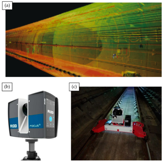
Figure 2. TLS for tunnel inspection. (a) 3D point cloud returned from a TLS metro tunnel survey [52]; (b) A FARO® FOCUS 350 scanning module, commonly deployed for infrastructure surveys; (c) TMMS rail-trolley transports a Z+F9012 to capture a TLS point cloud of a Zhengzhou metro tunnel.
Returning to standalone laser methods, we found TLS-RTI studies and commercial contractors most commonly deploy FARO® FOCUS scanning modules [46,47,48,49] (Figure 2b) or the Z+F Profiler® 9012 [50,51,52] to assimilate RGB optical photography for improved end-user navigational ease in recovered point clouds. Noteworthy innovations include an automated deformation detection assembly [11], which utilises a novel Circular Laser Scanning System (CLSS), highlighting the practicality of adopting circular sensing arrays that complement natural tunnel curvature.
Notable innovation is showcased in the Tunnel Monitoring and Measurement System (TMMS) developed by [52]. The prototype visualisation framework utilises a Z+F Profiler® 9012 mounted on a bespoke rail trolley (Figure 2c) to pass RGB LiDAR tunnel point clouds and a ‘roaming video’ feed of intrados condition to an engineer’s tablet PC. The developed hardware bares strong similarities with a similar mobile TLS apparatus used in [49] employing a FARO X330 scanner. Validation trials in China’s Zhengzhou Metro network demonstrate practical deployment capability but also relay that primary functions of ingress and cross-sectional deformation detection suffer noteworthy accuracy and stability reduction when applied to non-circular tunnel profiles (e.g., horseshoe, elliptical, etc.). TMMS therefore flags the importance adaptability in the design of new RTSSI solutions for wide-scale deployment, particularly on older rail networks (e.g., UK) which adopt multiple ‘standard’ tunnel cross-section variants.
4. Thermographic Methods
Subsurface faults modify thermal emission patterns of nearby interior tunnel surfaces, causing abnormal variations. Visualising temperature distribution profiles (Thermometry) facilitates localisation of suspected near-surface features (Thermography) [53,54], but recovery of specific attributes defers to higher quality UST or localised GPR imaging. Active Thermography (ACT) heats surfaces using halogen lamps [55], air guns [56] or inductive-heating elements [57] to induce exaggerated thermal responses. Abandoned testing by [58] and remarks of [59] affirm that heating element operation for RTSSI would incur impractical cost and could debond masonry, explaining its literary absence. We find use of infrared camera arrays for passive Infrared Thermography (IRT) more commonplace, owing to swifter and less costly implementation. Leading systems identify both air and water filled voids, with individual scans displayable as 2D panoramic imagery [53] or pioneering 3D mesh overlays on digital structural models rendered using TOSCA-FI [60] (Figure 3) or Augmented Reality [61] (Section 6.2). Despite recent work, Thermography still exhibits persistent limitations [54] undermining direct application to RTSSI:
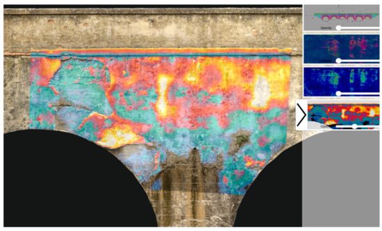
Figure 3. TOSCA-FI Software Platform: 2D heatmap overlays on a 3D digital bridge model [60].
-
Results are highly sensitive to ambient temperature conditions which diminishes anomaly contrast (e.g., daily and seasonal variation);
-
Thermal insulation and heat-resistant coatings used for tunnel temperate regulation and fire resilience can skew results. High thermal dissipation can easily restrict penetration d < 30 mm [62];
-
Subsurface water content variation (e.g., increased permeation following rainfall or snow) can mask or exaggerate thermal profiles of faults;
-
Enclosed, curved tunnel geometry restricts available viewing angles and confine results to 2D, even in a 3D mesh overlay, making inference of feature depth and physical form very challenging even for experienced operatives.
5. Gravity Methods
Gravity Surveys (GS) use portable gravimeters [63], placed at regularly spaced sampling locations, to measure subtle variation in gravity surrounding railway tunnels [64]. Anomalies observed in returned Complete Bouguer Anomaly (CBA) curves inform subsurface material composition [65] and indirectly, structural health assessment. Regional trends in subsurface density conveyed by CBA curves can vary across scales comparable to the tunnel itself, granting extensive inspection coverage. Likewise, localised negative field displacements can indicate the presence of irregular low density regions, strong indicators of voids and deformation zones [66,67,68]. However, few common defects exhibit substantially large density variations (compared to their surrounding landmass) that would noticeably influence a CBA curve, which despite informing the general nature of the subsurface, does not comprehensively nor clearly visualise subsurface features themselves. Moreover, localising large features relative to the tunnel (i.e., in front, behind, left, right) is further complicated by the structure’s cylindrical profile. This makes modelling the corresponding gravity field a multi-solution problem, introducing significant uncertainty and greatly increasing involved computation efforts [69].
6. Radar Methods
Ground Penetrating Radar (GPR) directs radio pulse emissions at the tunnel intrados, which penetrate and partially backscatter off strong dielectric gradients in the subsurface associated with features of interest [10,70,71,72,73]. Pulsed Radar (PR) samples consecutively emit wideband waveforms to measure backscatter in the time domain. Step-Frequency Continuous Wave (SFCW) radar incrementally sweeps an emission sinusoid through a pre-defined frequency band; the Fourier Spectrum of the returning signal is directly ascertained in the frequency domain by frequency-wise inspection of return signal strength [74]. In RTI, systems fall under three categories:
-
Trolley-Mounted [75,76,77] —Units commonly feature interchangeable air-coupled antenna of differing frequencies to facilitate trade-off between penetration depth and output image resolution [28]. However, motorisation is infrequent, scans are unidirectional (typically railbed only) and offer no protection to operatives;
-
Handheld [78,79,80,81]—Compact ground-coupled scanners guided by hand can achieve real-time scanning of curved tunnel sidewalls and crown. Typically restricted by limited penetrative depth (d < 50 cm), coverage speed (under m2 h−1) and gantry requirement to reach high surfaces make units impractical for full RTI;
7. Robotic Methods
Robotic systems reduce necessary human involvement in RTI, thereby beneficially reducing human error during data acquisition (e.g., mis-recordings due to subjectivity or lapses in concentration). Scope for varying degrees of autonomy further reduces dependency on onsite human presence, thereby increasing crew safety and cutting overhead costs. However, we must remember robotic methods share the limitations of their constituent sensors and also exhibit their own unique set of challenges (e.g., collision avoidance, recovery, stabilisation, power management, miniaturisation).
7.1. Unmanned Aerial Vehicles
Unmanned Aerial Vehicles (UAVs) have become increasingly popular for tunnel inspection owing to their low cost designs, programmability and exceptional manoeuvrability, which has motivated in excess of $4 billion global investment in UAV technology development for infrastructure inspection [124]. However, practical performance of current UAVs remains limited by poor onboard charge retention [125]; stabilisation challenges from near-wall turbulence and common dependency on GPS. Note that being subterranean, Global Positioning Systems (GPS) typically struggle to operate reliably in tunnels. [126,127]. Although, we did find considerable recent research applying collision-aversion protocol [128,129] and ‘smart pathfinding’ [130,131,132] (e.g., PLUTO [133]) to develop autonomous UAVs [134,135,136,137]. However, backup pilots remain necessary which add costs and safety-risks [137]. Furthermore, no commercially available autonomous UAV has yet to be developed specifically for RTSSI, despite similar systems existing for hydroelectric penstock surface level inspection [138].
Being airborne, UAVs could quickly transport RTSSI sensors where articulated booms cannot reach, for instance UAV-SWIRL hovers inside vertical ventilation shafts [125,139]. However, most systems still favour Optical Photometry and LiDAR sensing [140,141,142], permitting only implicit subsurface measurements. Of novel importance, we discuss several significant exceptions developed since 2015. These include development of new UAV-mounted GPR prototypes [143,144,145]; we found one commercial system [146] capable of 10 m penetration, however it is unclear if this incorporates UAV altitude.
In addition, hybrid locomotion UAVs now encompass:
-
Pivoting RTUs [151]—Tracks enable uninterrupted contact and continuous one-way surface coverage but increase weight and power drain, limiting survey completeness;
7.2. Adaptive Robots
We consider adaptive tunnel inspection robots to be devices capable of automatic geometry, operation or locomotion mechanism modification that combats demanding environmental conditions. As developments found were primarily proof-of-concept prototypes, current systems lack direct applicability to RTSSI without significant refinement efforts.
Nonetheless, we shall consider how such systems could be of practical future benefit in RTSSI. Foremost, adaption permits infiltration of inaccessible survey areas (e.g., drainage pipe interiors, capped shafts), increasing survey coverage. Moreover, units can swiftly traverse complex terrain (e.g., steps, rail tracks, damaged surfaces, angled walls) without human interaction, inviting remote inspection innovation potential.
Reconfigurable UAVs [156,157] fold to pass though narrow channels before unfolding to survey unknown void-like environments, which could be applied to preliminary surveys of hidden shafts via small diameter drill holes in capping facades. However, with more moving parts, damage likelihood during transit or execution is increased, potentially trapping systems behind walls incurring excess repair, replacement or recovery costs. Self-disassembly [158] could provide an easier route towards recovery.
8. BIM-Integration
Building Information Modelling (BIM)represents a new paradigm for large structure lifecycle information management [175,176]. Current survey outputs represent one-way information exchanges between the physical tunnel environment and reconstructed digital models. By contrast, Digital Twin Tunnel (DTT) BIMs would facilitate two-way information exchange from any point in time during its perpetual update cycle. In two-way exchange, state changes in physical tunnel prompt reactive changes in the digital tunnel informing future maintenance, which cause further state changes in the physical tunnel and so on and so forth [177].
We find multiple recent experimental rail tunnel-BIM studies exist [178,179,180,181,182], typically deploying laser methods to profile and categorise trackside assets but only [183] directly approaches RTSSI, developing a prototype AI-assisted BIM for ingress detection (developed on the Amber Inspection Could). Problematically, none currently exhibit adequate automation to be considered idealised DTTs. By inference, visualisation quality and overheads would clearly benefit from the significantly increased data pools and optimised network architectures anticipated [184]. However, challenges remain. Existing BIM architectures frequently lack specialisation to account for unique RTSSI challenges, such as complex terrain deformations and changeable subsurface geological conditions [182,185]. Reoccurring incompleteness of feeder data from NDI methods further limit BIM efficacy for RTSSI, despite recent improvements in multi-label datasets recovery [186,187,188,189].
Evidently, BIM integration for RTSSI will be essential for developing the first self-sustaining DTT [188], but insufficient without complimentary improvements to survey completeness.
9. Other Methods
Aforementioned NDI methods are most commonly deployed in routine RTSSI surveys based on encountered literature, motivating distinction from (i) more antiquated methods (e.g., invasive, inefficient, overly localised), (ii) less established experimental practices and (iii) schemes for real-time subsurface monitoring. In (i), we group: Borehole/Drill Core Sampling [190,191], Electrical Resistivity Tomography (ERT) [192,193,194,195], Endoscopic Probing [196,197] and Schmidt Hammer Strength Testing [53,198]. In group (ii), we gather: Radiography/Muon Tomography [199,200] and multiple additional prototype robotic RTSSI systems [14,166,201,202,203,204]. Group (iii) accounts for Time Domain Reflectometry schemes [205,206] and other Embedded Sensors [207].
This entry is adapted from the peer-reviewed paper 10.3390/app122211310
This entry is offline, you can click here to edit this entry!