The history of the oscilloscope reaches back to the first recordings of waveforms with a galvanometer coupled to a mechanical drawing system in the second decade of the 19th century. The modern day digital oscilloscope is a consequence of multiple generations of development of the oscillograph, cathode-ray tubes, analog oscilloscopes, and digital electronics.
- digital oscilloscope
- oscilloscope
- oscillograph
1. Hand-drawn Oscillograms
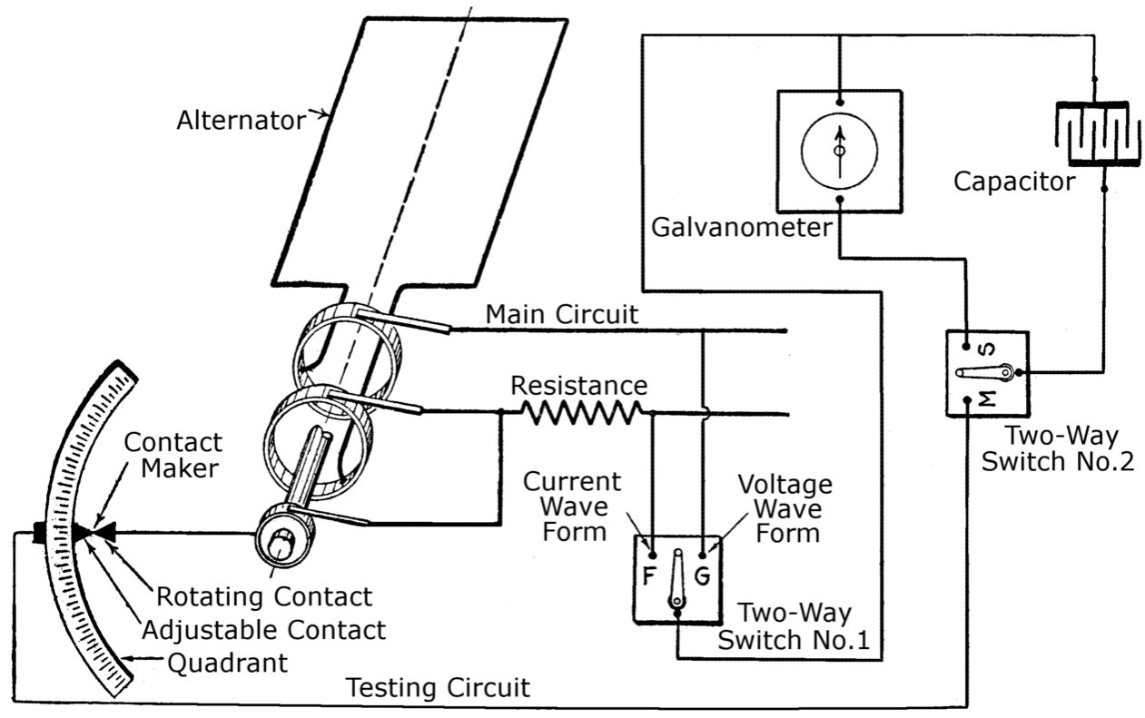
The earliest method of creating an image of a waveform was through a laborious and painstaking process of measuring the voltage or current of a spinning rotor at specific points around the axis of the rotor, and noting the measurements taken with a galvanometer. By slowly advancing around the rotor, a general standing wave can be drawn on graphing paper by recording the degrees of rotation and the meter strength at each position.
This process was first partially automated by Jules François Joubert with his step-by-step method of wave form measurement. This consisted of a special single-contact commutator attached to the shaft of a spinning rotor. The contact point could be moved around the rotor following a precise degree indicator scale and the output appearing on a galvanometer, to be hand-graphed by the technician.[2] This process could only produce a very rough waveform approximation since it was formed over a period of several thousand wave cycles, but it was the first step in the science of waveform imaging.
2. Automatic Paper-drawn Oscillograph
 |
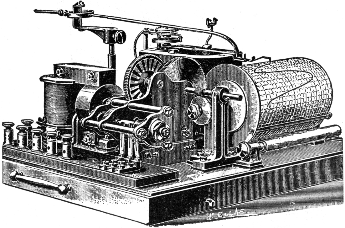 |
| Schematic and perspective view of the Hospitalier Ondograph, which used a pen on a paper drum to record a waveform image built up over time, using a synchronous motor drive mechanism and a permanent magnet galvanometer.[3][4] | |
The first automated oscillographs used a galvanometer to move a pen across a scroll or drum of paper, capturing wave patterns onto a continuously moving scroll. Due to the relatively high-frequency speed of the waveforms compared to the slow reaction time of the mechanical components, the waveform image was not drawn directly but instead built up over a period of time by combining small pieces of many different waveforms, to create an averaged shape.
The device known as the Hospitalier Ondograph was based on this method of wave form measurement. It automatically charged a capacitor from each 100th wave, and discharged the stored energy through a recording galvanometer, with each successive charge of the capacitor being taken from a point a little farther along the wave.[5] (Such wave-form measurements were still averaged over many hundreds of wave cycles but were more accurate than hand-drawn oscillograms.)
3. Photographic Oscillograph
 |
 |
 |
 |
||
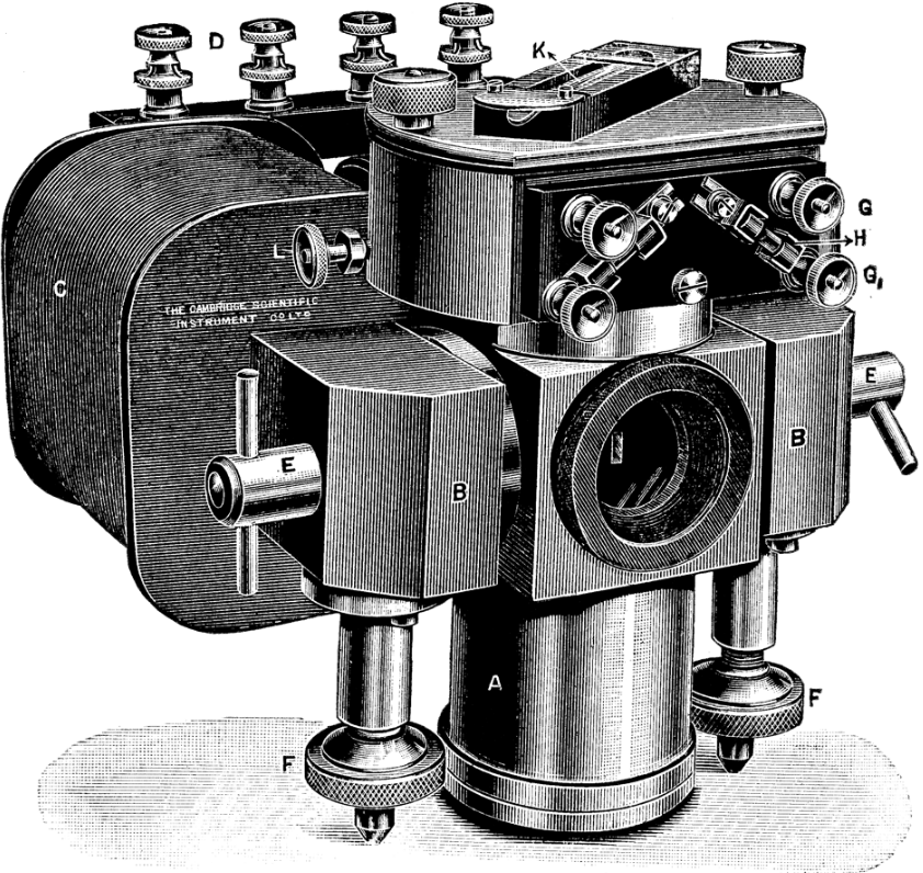
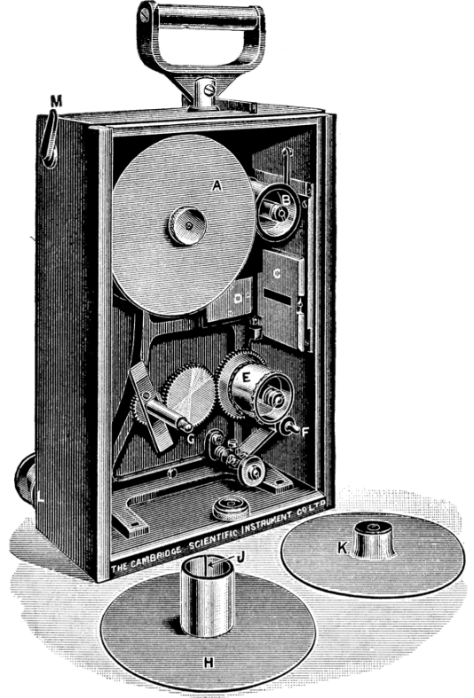
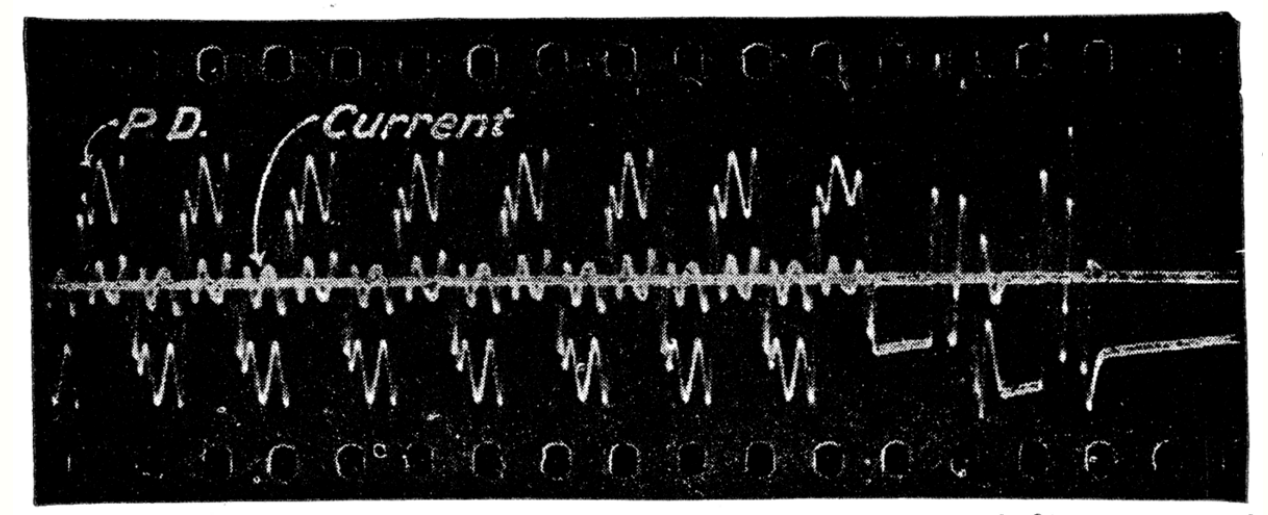
| Top-Left: Duddell moving-coil oscillograph with mirror and two supporting moving coils on each side of it, suspended in an oil bath. The large coils on either side are fixed in place, and provide the magnetic field for the moving coil. (Permanent magnets were rather feeble at that time.) Top-Middle: Rotating shutter and moving mirror assembly for placing time-index marks next to the waveform pattern. Top-Right: Moving-film camera for recording the waveform. Bottom: Film recording of sparking across switch contacts, as a high-voltage circuit is disconnected.[6][7][8][9] | ||
In order to permit direct measurement of waveforms it was necessary for the recording device to use a very low-mass measurement system that can move with sufficient speed to match the motion of the actual waves being measured. This was done with the development of the moving-coil oscillograph by William Duddell which in modern times is also referred to as a mirror galvanometer. This reduced the measurement device to a small mirror that could move at high speeds to match the waveform.
To perform a waveform measurement, a photographic slide would be dropped past a window where the light beam emerges, or a continuous roll of motion picture film would be scrolled across the aperture to record the waveform over time. Although the measurements were much more precise than the built-up paper recorders, there was still room for improvement due to having to develop the exposed images before they could be examined.
4. A Tiny Tilting Mirror
In the 1920s, a tiny tilting mirror attached to a diaphragm at the apex of a horn provided good response up to a few kHz, perhaps even 10 kHz. A time base, unsynchronized, was provided by a spinning mirror polygon, and a collimated beam of light from an arc lamp projected the waveform onto the lab wall or a screen.
Even earlier, audio applied to a diaphragm on the gas feed to a flame made the flame height vary, and a spinning mirror polygon gave an early glimpse of waveforms.
Moving-paper oscillographs using UV-sensitive paper and advanced mirror galvanometers provided multi-channel recordings in the mid-20th century. Frequency response was into at least the low audio range.
5. CRT Invention
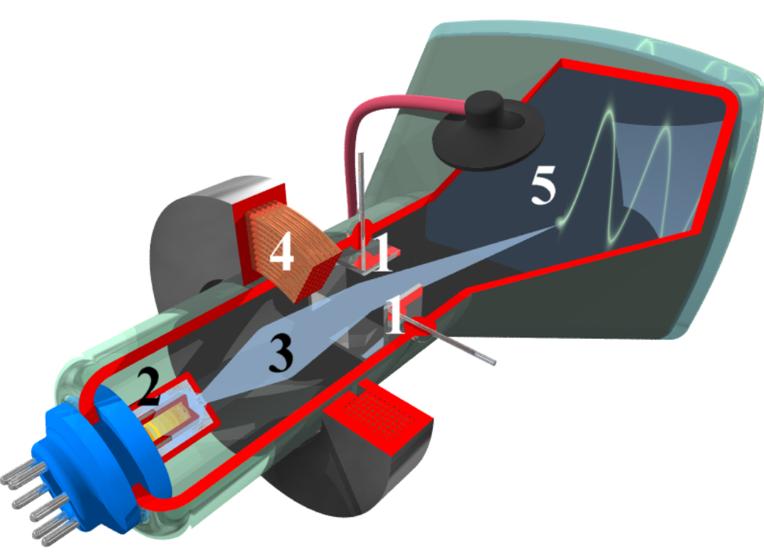
Cathode ray tubes (CRTs) were developed in the late 19th century. At that time, the tubes were intended primarily to demonstrate and explore the physics of electrons (then known as cathode rays). Karl Ferdinand Braun invented the CRT oscilloscope as a physics curiosity in 1897, by applying an oscillating signal to electrically charged deflector plates in a phosphor-coated CRT. Braun tubes were laboratory apparatus, using a cold-cathode emitter and very high voltages (on the order of 20,000 to 30,000 volts). With only vertical deflection applied to the internal plates, the face of the tube was observed through a rotating mirror to provide a horizontal time base.[10] In 1899 Jonathan Zenneck equipped the cathode ray tube with beam-forming plates and used a magnetic field for sweeping the trace.[11]
Early cathode ray tubes had been applied experimentally to laboratory measurements as early as 1919 [12] but suffered from poor stability of the vacuum and the cathode emitters. The application of a thermionic emitter allowed operating voltage to be dropped to a few hundred volts. Western Electric introduced a commercial tube of this type, which relied on a small amount of gas within the tube to assist in focusing the electron beam.[12]
V. K. Zworykin described a permanently sealed, high-vacuum cathode ray tube with a thermionic emitter in 1931. This stable and reproducible component allowed General Radio to manufacture an oscilloscope that was usable outside a laboratory setting.[11]
The first dual-beam oscilloscope was developed in the late 1930s by the British company A.C.Cossor (later acquired by Raytheon). The CRT was not a true double beam type but used a split beam made by placing a third plate between the vertical deflection plates. It was widely used during WWII for the development and servicing of radar equipment. Although extremely useful for examining the performance of pulse circuits it was not calibrated so could not be used as a measuring device. It was, however, useful in producing response curves of IF circuits and consequently a great aid in their accurate alignment.
Allen B. Du Mont Labs. made moving-film cameras, in which continuous film motion provided the time base. Horizontal deflection was probably disabled, although a very slow sweep would have spread phosphor wear. CRTs with P11 phosphor were either standard or available.
Long-persistence CRTs, sometimes used in oscilloscopes for displaying slowly changing signals or single-shot events, used a phosphor such as P7, which comprised a double layer. The inner layer fluoresced bright blue from the electron beam, and its light excited a phosphorescent "outer" layer, directly visible inside the envelope (bulb). The latter stored the light, and released it with a yellowish glow with decaying brightness over tens of seconds. This type of phosphor was also used in radar analog PPI CRT displays, which are a graphic decoration (rotating radial light bar) in some TV weather-report scenes.
6. Sweep Circuit
The technology for the horizontal sweep, that portion of the oscilloscope that creates the horizontal time axis, has changed.
6.1. Synchronized Sweep

Early oscilloscopes used a synchronized sawtooth waveform generator to provide the time axis. The sawtooth would be made by charging a capacitor with a relatively constant current; that would create a rising voltage. The rising voltage would be fed to the horizontal deflection plates to create the sweep. The rising voltage would also be fed to a comparator; when the capacitor reached a certain level, the capacitor would be discharged, the trace would return to the left, and the capacitor (and the sweep) would start another traverse. The operator would adjust the charging current so the sawtooth generator would have a slightly longer period than a multiple of the vertical axis signal. For example, when looking at a 1 kHz sinewave (1 ms period), the operator might adjust the horizontal frequency to a little bit more than 5 ms. When the input signal was absent, the sweep would free run at that frequency.
If the input signal were present, the resulting display would not be stable at the horizontal sweep's free-running frequency because it was not a submultiple of the input (vertical axis) signal. To fix that, the sweep generator would be synchronized by adding a scaled version of the input the signal to the sweep generator's comparator. The added signal would cause the comparator to trip a little earlier and thus synchronize it to the input signal. The operator could adjust the synch level; for some designs, the operator could choose the polarity.[13] The sweep generator would turn off (known as blanking) the beam during retrace.[14]
The resulting horizontal sweep speed was uncalibrated because the sweep rate was adjusted by changing slope of the sawtooth generator. The time per division on the display depended upon the sweep's free-running frequency and a horizontal gain control.
A synchronized sweep oscilloscope could not display a non-periodic signal because it could not synchronize the sweep generator to that signal. Horizontal circuits were often AC-coupled
6.2. Triggered Sweep
During World War II, a few oscilloscopes used for radar development (and a few laboratory oscilloscopes) had so-called driven sweeps. These sweep circuits remained dormant, with the CRT beam cut off, until a drive pulse from an external device unblanked the CRT and started a constant-speed horizontal trace; the calibrated speed permitted measurement of time intervals. When the sweep was complete, the sweep circuit blanked the CRT (turned off the beam), reset itself, and waited for the next drive pulse. The Dumont 248, a commercially available oscilloscope produced in 1945, had this feature.
Oscilloscopes became a much more useful tool in 1946 when Howard Vollum and Melvin Jack Murdock introduced the Tektronix Model 511 triggered-sweep oscilloscope. Howard Vollum had first seen this technology in use in Germany. The triggered sweep has a circuit that develops the driven sweep's drive pulse from the input signal.
Triggering allows stationary display of a repeating waveform, as multiple repetitions of the waveform are drawn over exactly the same trace on the phosphor screen. A triggered sweep maintains the calibration of sweep speed, making it possible to measure properties of the waveform such as frequency, phase, rise time, and others, that would not otherwise be possible.[15] Furthermore, triggering can occur at varying intervals, so there is no requirement that the input signal be periodic.
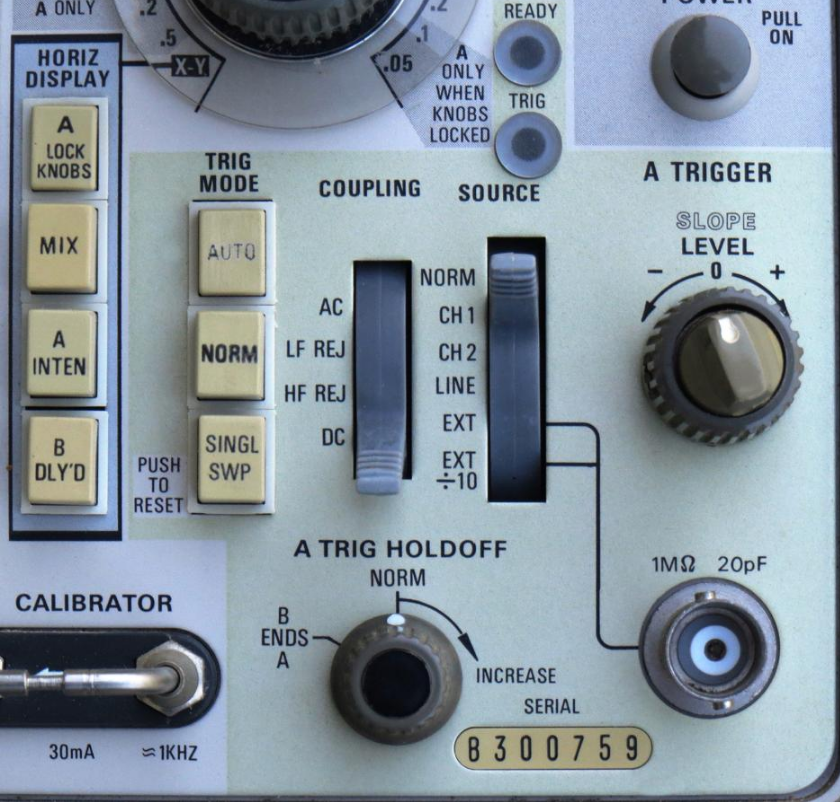
Triggered-sweep oscilloscopes compare the vertical deflection signal (or rate of change of the signal) with an adjustable threshold, referred to as trigger level. As well, the trigger circuits also recognize the slope direction of the vertical signal when it crosses the threshold—whether the vertical signal is positive-going or negative-going at the crossing. This is called trigger polarity. When the vertical signal crosses the set trigger level and in the desired direction, the trigger circuit unblanks the CRT and starts an accurate linear sweep. After the completion of the horizontal sweep, the next sweep will occur when the signal once again crosses the threshold trigger.
Variations in triggered-sweep oscilloscopes include models offered with CRTs using long-persistence phosphors, such as type P7. These oscilloscopes were used for applications where the horizontal trace speed was very slow, or there was a long delay between sweeps, to provide a persistent screen image. Oscilloscopes without triggered sweep could also be retro-fitted with triggered sweep using a solid-state circuit developed by Harry Garland and Roger Melen in 1971.[16]
As oscilloscopes have become more powerful over time, enhanced triggering options allow capture and display of more complex waveforms. For example, trigger holdoff is a feature in most modern oscilloscopes that can be used to define a certain period following a trigger during which the oscilloscope will not trigger again. This makes it easier to establish a stable view of a waveform with multiple edges which would otherwise cause another trigger.
7. Tektronix
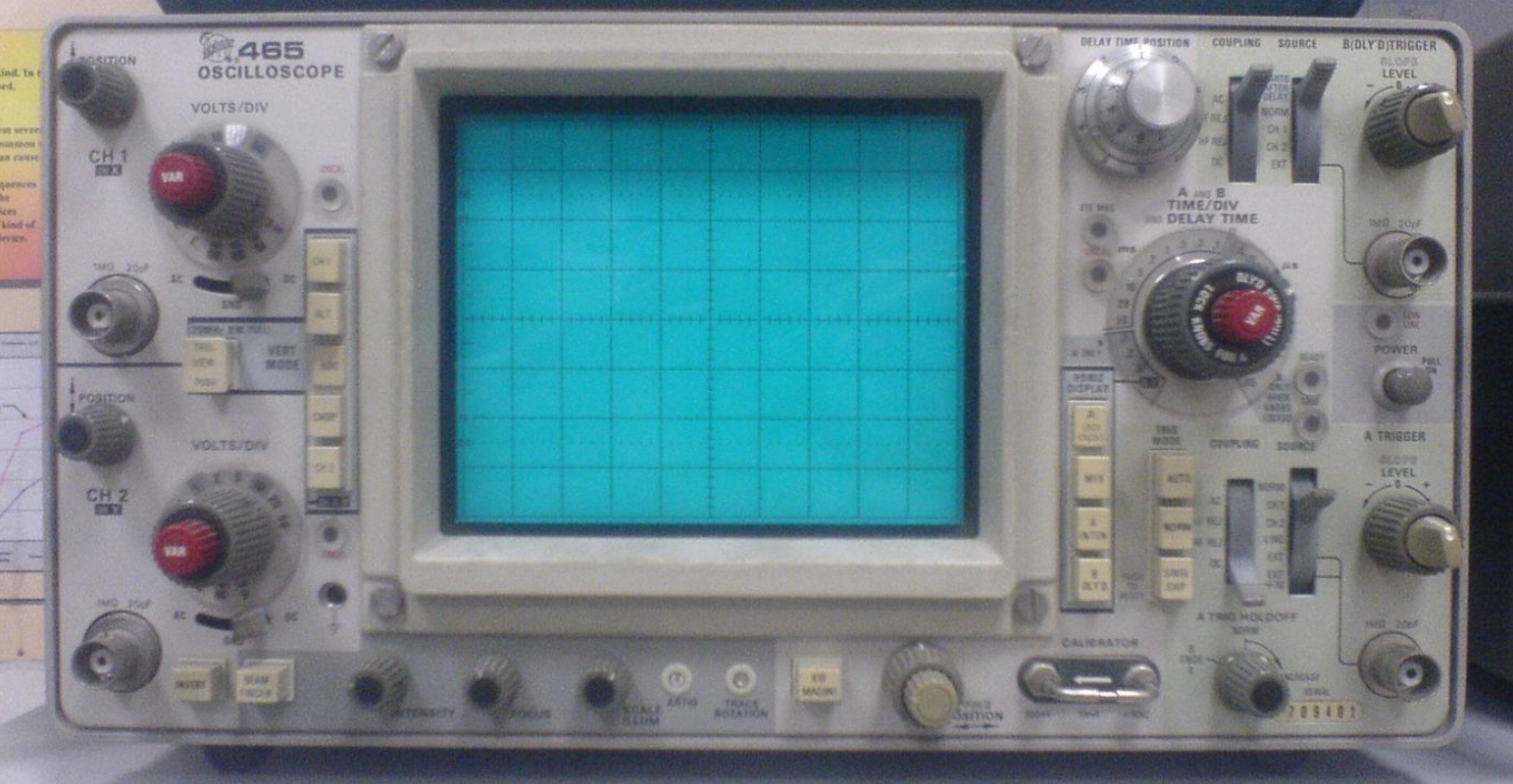
Vollum and Murdock went on to found Tektronix, the first manufacturer of calibrated oscilloscopes (which included a graticule on the screen and produced plots with calibrated scales on the axes of the screen). Later developments by Tektronix included the development of multiple-trace oscilloscopes for comparing signals either by time-multiplexing (via chopping or trace alternation) or by the presence of multiple electron guns in the tube. In 1963, Tektronix introduced the Direct View Bistable Storage Tube (DVBST), which allowed observing single pulse waveforms rather than (as previously) only repeating wave forms. Using micro-channel plates, a variety of secondary-emission electron multiplier inside the CRT and behind the faceplate, the most advanced analog oscilloscopes (for example, the Tek 7104 mainframe) could display a visible trace (or allow the photography) of a single-shot event even when running at extremely fast sweep speeds. This oscilloscope went to 1 GHz.
In vacuum-tube oscilloscopes made by Tektronix, the vertical amplifier's delay line was a long frame, L-shaped for space reasons, that carried several dozen discrete inductors and a corresponding number of low-capacitance adjustable ("trimmer") cylindrical capacitors. These oscilloscopes had plug-in vertical input channels. For adjusting the delay line capacitors, a high-pressure gas-filled mercury-wetted reed switch created extremely fast-rise pulses which went directly to the later stages of the vertical amplifier. With a fast sweep, any misadjustment created a dip or bump, and touching a capacitor made its local part of the waveform change. Adjusting the capacitor made its bump disappear. Eventually, a flat top resulted.
Vacuum-tube output stages in early wideband oscilloscopes used radio transmitting tubes, but they consumed a lot of power. Picofarads of capacitance to ground limited bandwidth. A better design, called a distributed amplifier, used multiple tubes, but their inputs (control grids) were connected along a tapped L-C delay line, so the tubes' input capacitances became part of the delay line. As well, their outputs (plates/anodes) were likewise connected to another tapped delay line, its output feeding the deflection plates. This amplifier was often push-pull, so there were four delay lines, two for input (grid), and two for output (plate).
8. Digital Oscilloscopes
The first digital storage oscilloscope (DSO) was built by Nicolet Test Instrument of Madison, Wisconsin. It used a low-speed analog-to-digital converter (1 MHz, 12 bit) used primarily for vibration and medical analysis. The first high-speed DSO (100 MHz, 8 bit) was developed by Walter LeCroy, who founded the LeCroy Corporation of New York, USA, after producing high-speed digitizers for the research center CERN in Switzerland. LeCroy (since 2012 Teledyne LeCroy) remains one of the three largest manufacturers of oscilloscopes in the world.
Starting in the 1980s, digital oscilloscopes became prevalent. Digital storage oscilloscopes use a fast analog-to-digital converter and memory chips to record and show a digital representation of a waveform, yielding much more flexibility for triggering, analysis, and display than is possible with a classic analog oscilloscope. Unlike its analog predecessor, the digital storage oscilloscope can show pre-trigger events, opening another dimension to the recording of rare or intermittent events and troubleshooting of electronic glitches. As of 2006 most new oscilloscopes (aside from education and a few niche markets) are digital.
Digital scopes rely on effective use of the installed memory and trigger functions: not enough memory and the user will miss the events they want to examine; if the scope has a large memory but does not trigger as desired, the user will have difficulty finding the event.
DSOs also led to the creation of hand-held digital oscilloscopes (pictured), useful for many test and field service applications. A hand held oscilloscope is usually a real-time oscilloscope, using a monochrome or color liquid crystal display for its display.
Due to the rise in the prevalence of PCs, PC-based oscilloscopes have been becoming more common. The PC platform can be part of a standalone oscilloscope or as a standalone PC in combination with an external oscilloscope. With external oscilloscopes, a signal will be captured on external hardware (which includes an analog-to-digital converter and memory) and transmitted to the computer, where it is processed and displayed.
The content is sourced from: https://handwiki.org/wiki/Engineering:Oscilloscope_history
References
- (Hawkins 1917) Fig. 2589
- (Hawkins 1917)
- (Hawkins 1917), Fig. 2597
- (Hawkins 1917), Fig. 2598
- (Hawkins 1917)
- (Hawkins 1917), Fig. 2607
- (Hawkins 1917), Fig. 2620
- (Hawkins 1917), Figs. 2621–2623
- (Hawkins 1917), Fig. 2625
- (Abramson 1995)
- Kularatna, Nihal (2003). "Chapter 5: Fundamentals of Oscilloscopes". Digital and analogue instrumentation: testing and measurement. Institution of Engineering and Technology. p. 165. ISBN 978-0-85296-999-1. https://books.google.com/books?id=Ac5iYqHCcucC&pg=PA165. Retrieved 2011-01-19.
- (Burns 1998)
- Operator's Manual: Model KG-635 DC to 5.2 MC 5" Wideband Oscilloscope, Maywood, IL: Knight Electronics Corporation, 1965, p. 3, "Synchronization ... + internal, − internal, 60 cps, and external. Sync limiting provides semi-automatic operation with level control. Locks from waveform fundamentals up to 5 mc. Will sync on display amplitudes as low as 0.1 [inch]" The KG-635 sync amplifier used a 12AT7 differential amplifier (V5). (id p. 15.) Sync level control would bias the amplifier into cutoff so action would only occur near the end of the sweep; the sync output was a negative pulse to the sweep generator; a diode pulse limiter clamped the sync pulse. (id p. 18.)
- KG-635 p. 18 stating, "Retrace blanking is obtained from the plate of V-6A and applied to the cathode of the CRT."
- Spitzer & Howarth 1972, p. 122
- Garland, Harry; Melen, Roger (1971). "Add Triggered Sweep to your Scope". Popular Electronics 35 (1): 61–66.
