There is an increasing interest in improving energy efficiency and reducing operational costs of induction motors in the industry. These costs can be significantly reduced, and the efficiency of the motor can be improved if the condition of the machine is monitored regularly and if monitoring techniques are able to detect failures at an incipient stage. An early fault detection makes the elimination of costly standstills, unscheduled downtime, unplanned breakdowns, and industrial injuries possible. Furthermore, maintaining a proper motor operation by reducing incipient failures can reduce motor losses and extend its operating life. There are many review papers in which analyses of fault detection techniques in induction motors can be found. However, all these reviewed techniques can detect failures only at developed or advanced stages. To our knowledge, no review exists that assesses works able to detect failures at incipient stages. This paper presents a review of techniques and methodologies that can detect faults at early stages. The review presents an analysis of the existing techniques focusing on the following principal motor components: stator, rotor, and rolling bearings. For steady-state and transient operating modes of the motor, the methodologies are discussed and recommendations for future research in this area are also presented.
1. Introduction
Electric motor failures in industrial systems often result in unplanned downtime, loss of production, higher operating costs, and loss of profits [
1]. The most common family of electric motors used in homes, businesses, and industry is the induction motor (IM) [
2], for which there is a variety to choose from, depending on the power source, load requirements, mechanical interface, operating cost, energy efficiency, and reliability. IMs are often preferred over other kinds of motors since they are significantly less expensive, more robust, and capable of reliable operation in harsh ambient conditions, even in an explosive atmosphere. Induction motors, particularly those of the squirrel cage type, have been for almost a century the principal workhorse in industry [
3]. Although IMs are more reliable than other types of motors, these machines are not exempt from developing faults in their structure or components, and these failures could lead to motor malfunction. Therefore, reliable condition monitoring for induction motors is of great value to avoid catastrophic unscheduled downtime [
4]. An unexpected failure might lead to the loss of valuable human life or a costly standstill in industry, which needs to be prevented by precisely detecting the fault. The induction motor consists of many mechanical and electrical parts, such as a motor frame, stator windings, rotor cage, rolling bearings, fan, rotor shaft, among others. Despite induction motors are designed to be robust machines, they are exposed to external situations such as unstable supply voltage, unstable supply current sources, overloads, unbalanced loads, and electrical stresses. Due to the above-mentioned situations, damages in operation and natural deterioration of the material parts (or manufacturing defects), the motor will eventually develop a faulty condition.
Different condition states of an IM component can be characterized as healthy or faulty condition. In the healthy condition, the internal components have no degradation, and the induction motor operates with maximum energy efficiency. There are three states that characterize a faulty condition in IM. The first one consists in an incipient fault, known as the early stage, where the degradation begins to develop in one or several of the internal components. Although the motor component has damage (i.e., partially broken rotor bars), the induction motor can continue to operate with no apparent symptoms. In the second faulty state, known as the developed fault, the damage on the motor component is advanced (i.e., one or more broken rotor bars). In this condition, the IM still operates; however, the damaged component severely affects the motor performance. Finally, the third faulty condition, known as catastrophic fault, occurs when the developed failure has propagated to other components, and the IM is no longer operating. Three stages of fault growth can be considered for an IM: the incipient fault with a steady propagation, the advanced fault with an accelerated propagation, and the catastrophic stage with a very accelerated propagation. The first stage is from the healthy state of the component until the very incipient fault state. This stage covers most of the portion of the IM component’s useful life. After the incipient fault is present, the degradation propagates slowly until the developed fault state is reached. Once the IM component presents developed fault symptoms, the last stage is the accelerated propagation, where the fault grows rapidly until a breakdown. The early detection of IM faults is carried out before an internal component exhibits a developed fault stage. According to the literature, the tendency in industry and academia is to consider incipient fault of the rotor or bearing when there exists only a partial fracture of an internal component. Whereas for the stator, it considers incipient fault when there exists a short circuit among less than 3% of the total turns winding.
2. Faults in Induction Motors
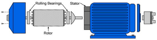
Induction motor faults are commonly categorized as mechanical faults and electrical faults. Despite the existence of many fault classifications, this work categorizes motor failures according to the component that develops the fault for the sake of simplicity. The most common failures occur in three principal components of the rotatory machine. Figure 1 shows these main parts: the stator, the rotor, and rolling bearings.
Figure 1. Three fundamental components of an induction motor: stator, rotor, and rolling bearings.
2.1. Stator Faults
The stator consists of a laminated core, an outer frame, and insulated electrical windings. Its components are subjected to electrical and environmental stresses, which severely affect the stator condition leading to faults [
17]. Stator faults (SF) can be categorized based on their localization as failure in the stator frame, fault in the stator winding, and failure in the laminations of the stator core. Among these, stator winding failures are the most severe faults and are often caused by failure of insulation of winding, which leads to local heating. If unnoticed, this local heating further damages the insulation of the stator winding until a catastrophic failure may occur. This fault is also known as the short circuit inter-turn fault. The appearance of stator faults depends on the size of the electrical machine [
18]. According to [
19], low-voltage IM stator faults account for only 9% of total failures. In medium-voltage IM, the percentage increases to 35–40%, whereas for high-voltage IM, it is more than 65%.
2.2. Rotor Faults
The rotor is the main driving shaft in induction motors through which the mechanical energy is transferred to the load. This component is placed inside the stator, and for a squirrel-cage type, it consists of the shaft, the aluminum or copper bars, and the end rings. Approximately 8 to 10% of all failures in IM are at the rotor. These faults can be classified as: broken rotor bars (BRB), cracked end-ring, and rotor eccentricities. Broken bars are caused by a combination of different stresses (mechanical, electrical, and thermal), manufacturing problems, dynamic stress from shaft torque, and fatigued mechanical parts [
12]. This type of fault may not show any incipient symptoms, propagating to the next bars and leading to a sudden collapse of the rotor, producing damage in the stator and an abrupt interruption of the motor operation [
20]. On the other hand, air-gap irregularities are produced by rotor eccentricities when the rotor axis of rotation does not coincide with stator geometrical axis. Manufacturing and constructive errors that generate a non-uniform air-gap or an incorrect positioning of the stator and rotor at the commissioning stage produce static eccentricity. When the center of the rotor is not at the center of rotation, then dynamic eccentricity is produced. The common causes of dynamic eccentricity are rotor shaft bending and bearing faults.
2.3. Rolling Bearing Faults
Rolling element bearings are the support of the shaft rotor in the induction motor in order to facilitate its rotation by reducing friction. In a rough manner, a bearing has four components: an inner raceway, an outer raceway, balls, and a cage that provides an equidistant arrangement between the balls. Bearing faults (BF) are classified as localized failures and distributed faults (roughness or non-cyclic) [
7]. Distributed defects affect a whole region and their mathematical modeling is very difficult. In contrast, localized failures are single-point defects and can be classified according to the affected element: inner raceway defect, outer raceway defect, ball defect, and cage failure. Bearing wear can be caused by a wide variety of reasons, such as excessive or deficient lubrication (due to inadequate viscosity, excess or lack of grease, lubricant contamination, etc.), circulation of bearing currents (in power converter-fed motors), brinelling (due to punctual overloads, severe impacts), etc.
2.4. Early Detection of Faults
Induction motors are symmetric machines and the occurrence of any type of fault is linked to the harmonic content of its monitored signals. The existence of a fault in IM results in the appearance of specific frequency signatures. In general, fault detection techniques are based on the magnitude evaluation of these signatures. When there is an anomaly in the mechanical structure of the rolling bearing, characteristic frequencies emerge in the vibration spectrum as a consequence of the asymmetry. There are two bearing defects that are analyzed in the literature from the severity level point of view, the outer race defect and the inner race defect. The related frequencies are shown below [
21].
where
fr is the rotational frequency,
Nb is the number of balls in the bearing,
Dc is the pitch or cage diameter,
Db the diameter of the balls, and
β is the contact angle between a ball and the raceway. When a stator fault occurs, the current through the shorted winding affects the magnetic field and is reflected in the axial flux as follows [
22].
where
k is the order of the time harmonic,
n the order of the shorted coil space harmonic,
s the machine slip,
p the number of pole pairs, and
fs the supply frequency. The damage of broken bars in the rotor produces additional frequencies in the current spectrum. These signatures are characterized by [
23]:
Additionally, any fluctuation in the load torque will produce oscillations in the stator currents at frequencies of
where
m is the order of the harmonic. Since the same fault harmonic is given by BRB, a low-frequency load-oscillation results in stator currents that can overlap those produced by the BRB fault [
24].
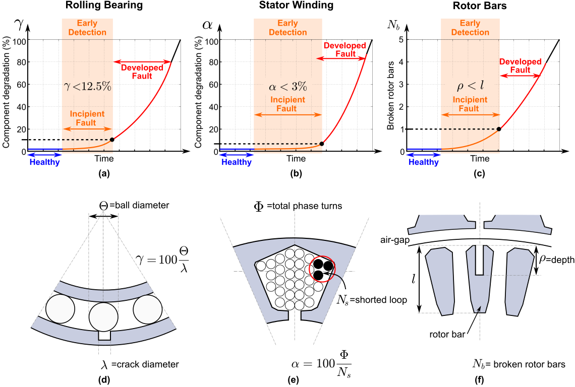
The magnitude of each of these fault frequencies is directly related to the severity level of the fault. The higher the severity level, the higher the magnitude of the spectral component. Each failure type has a different evolution over time since the degradation of the component depends on its construction and the material from which it is made. Figure 2 illustrates the degradation of the motor components and its severity levels: bearing failure (Figure 2a), stator failure (Figure 2b), and rotor fault (Figure 2c). The tendency in industry and academia is to be able to make an early detection of the motor component degradation. For bearing failure, the early detection is considered when the diameter of the crack (λ) is less than 1/8 the diameter of the bearing ball (Θ). For broken rotor bars, early detection is considered when one bar is partially broken and the depth of the breakage (ρ) is less than the total length of the bar (l). Whereas for stator faults, it is considered that an early fault occurs when there is a short circuit between less than 1/30 times the total turns of the winding (Φ). Figure 2d–f illustrates the relationships of the fault with the construction of the motor components. As component degradation is very low at an early stage, the magnitude of fault signatures is also very low. Therefore, a condition diagnosis of the motor component when the degradation is incipient presents a challenge in the detection, identification, and evaluation of failure indicators.
Figure 2. Degradation stages of induction motor components: (a) rolling bearing degradation, (b) stator winding degradation, (c) rotor bar degradation, (d) rolling bearing schematic, (e) stator winding schematic, and (f) rotor bars schematic.
The most important characteristic of any condition monitoring scheme is its quickness of detection. Different types of faults usually progress from incipient to a very advanced stage in a different manner, as is shown in Figure 2. This work only considers fault detection at an early stage. For the detection of early rotor failure, only partially broken rotor bars are taken into account, whereas fully broken rotor bars are considered a developed fault. This is because once a bar is completely fractured, the failure spreads rapidly to adjacent bars and subsequently damages the stator winding causing irreparable damage. In the case of bearing faults, the early fault condition is considered when the diameter of the fracture in the inner or the outer race is less than 12.5% of the diameter of the bearing ball, since from then on, the bearing stroke undergoes great alterations and alters the rotor symmetry, making the failure to be considered as developed or advanced. Finally, the stator failure is considered in an early condition before exceeding 3.33% of the turns in the stator phase. Once the short circuit begins, it propagates rapidly in a very short time. Unless detected early enough, it might lead to catastrophic consequences. Faults detected at advanced stages are far more likely to cause unplanned breakdowns in the line production than those detected while the failure is still at an early stage. Techniques that can detect faults at an early stage are very desirable for the possibility of correcting the faulty condition entirely with low impact to the production line. For early detection to be an effective and practical approach, techniques must satisfy three basic requirements. First, the detection analysis should be able to distinguish faulty IM from healthy IM cases with a high degree of accuracy, showing both low rates of false-positives and false negatives. Second, the detection should be possible before the fault progresses to a developed stage, when the propagation is accelerated, and preventive actions are less effective. Lastly, the diagnosis methodology should allow the assessment of the IM condition when the motor is fed by inverters. It must be noticed that inverters induce several spectral components to the voltage, current, and vibration signals, which overlap with the fault-related spectral signatures; moreover, the magnitude of the fault-related components are very close to the noise floor, making the evaluation of the fault severity difficult.
This entry is adapted from the peer-reviewed paper 10.3390/en15217855