The multicomponent alloys with nearly equal concentration of components are known as high entropy alloys (HEAs). The HEAs quickly became very important in materials science due to their unique properties. Nowadays, the HEAs are frequently used in energy conversion and storage applications. HEAs can consist of five, six or more components. Plasma cladding permits coating of the large surfaces of cheap substrates with (often expensive) HEAs and to enlarge, in such a way, their application area. The large-area coatings deposited by plasma cladding possess multiple advantages such as low thermal distortion, very high energy density, as well as low dilution of the substrate material. Plasma cladding ensures good metallurgical bonding between coating and substrate. The costs of operation and equipment are also very attractive. During plasma cladding, the mixed powders are blown by carrier gas into a plasma torch or are positioned on a substrate.
- plasma cladding
- coatings
- wetting
- phase transitions
- high-entropy alloys
- phase diagrams
- grain boundary
1. Introduction
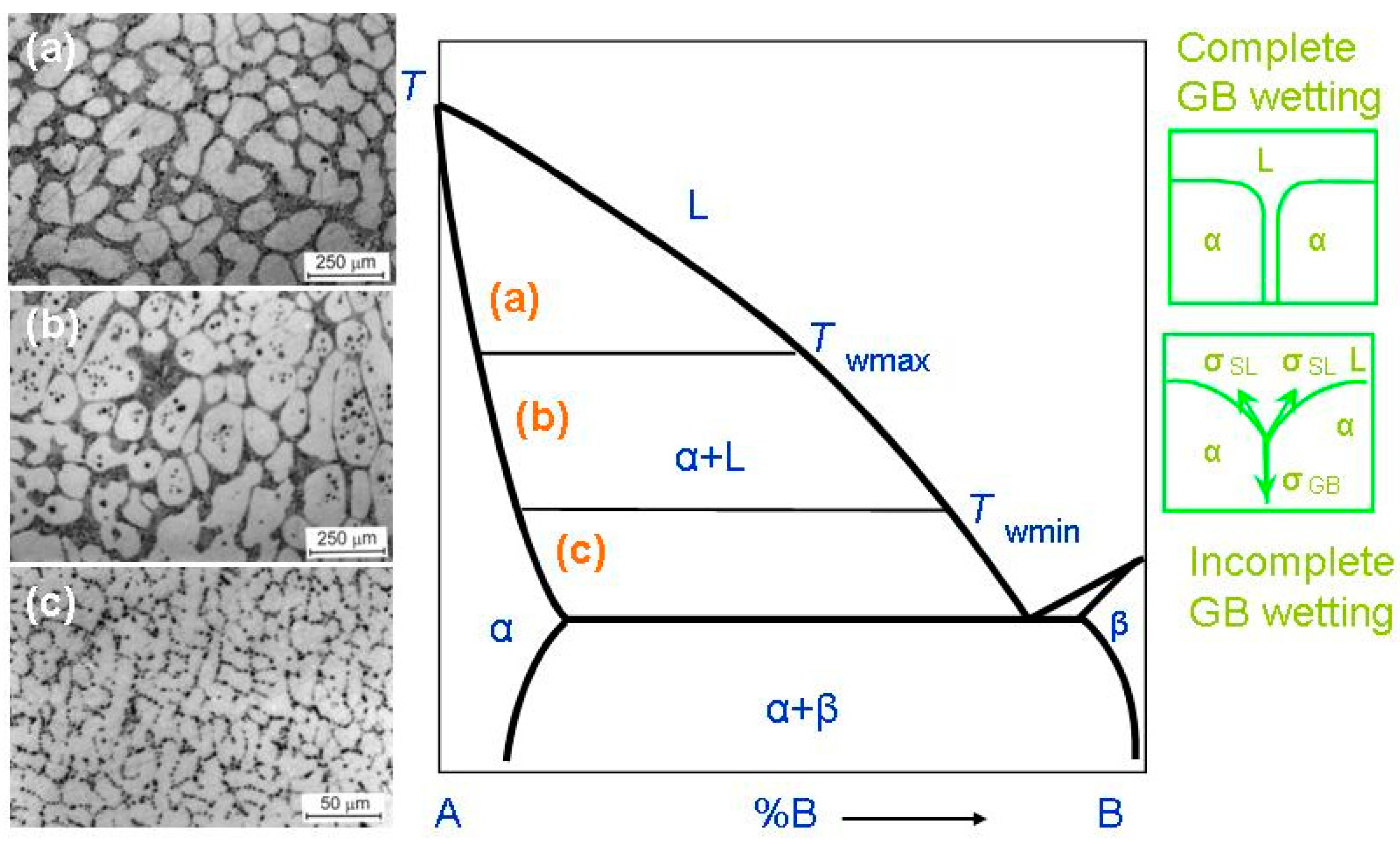
2. Grain Boundary Wetting Phase Transitions
This entry is adapted from the peer-reviewed paper 10.3390/en15197130
References
- Zhou, H.; He, J. Synthesis of the new high entropy alloy and its application in energy conversion and storage. Front. Energy Res. 2020, 8, 73.
- Amiri, A.; Shahbazian-Yassar, R. Recent progress of high-entropy materials for energy storage and conversion. J. Mater. Chem. A 2021, 9, 782–823.
- Liu, H.; Syama, L.; Zhang, L.; Lee, C.; Liu, C.; Dai, Z.; Yan, Q. High-entropy alloys and compounds for electrocatalytic energy conversion applications. SusMat 2021, 1, 482–505.
- Fu, M.; Ma, X.; Zhao, K.; Li, X.; Su, D. High-entropy materials for energy-related applications. iScience 2021, 24, 102177.
- Cantor, B.; Chang, I.T.H.; Knight, P.; Vincent, A.J.B. Microstructural development in equiatomic multicomponent alloys. Mater. Sci. Eng. A 2004, 375–377, 213–218.
- Yeh, J.-W.; Chen, S.-K.; Lin, S.-J.; Gan, J.-Y.; Chin, T.-S.; Shun, T.-T.; Tsau, C.-H.; Chang, S.-Y. Nanostructured high-entropy alloys with multiple principal elements: Novel alloy design concepts and outcomes. Adv. Eng. Mater. 2004, 6, 299–303.
- Zhu, J.M.; Fu, H.M.; Zhang, H.F.; Wang, A.M.; Li, H.; Hu, Z.Q. Synthesis and properties of multiprincipal component AlCoCrFeNiSix alloys. Mater. Sci. Eng. A 2010, 527, 7210–7214.
- Zhou, Y.J.; Zhang, Y.; Wang, Y.L.; Chen, G.L. Solid solution alloys of AlCoCrFeNiTix with excellent room-temperature mechanical properties. Appl. Phys. Lett. 2007, 90, 181904.
- Hsu, C.Y.; Juan, C.C.; Wang, W.R.; Sheu, T.S.; Yeh, J.W.; Chen, S.K. On the superior hot hardness and softening resistance of AlCoCrxFeMo0.5Ni high-entropy alloys. Mater. Sci. Eng. A 2011, 528, 3581–3588.
- Chuang, M.H.; Tsai, M.H.; Wang, W.R.; Lin, S.J.; Yeh, J.W. Microstructure and wear behavior of AlxCo1.5CrFeNi1.5Tiy high-entropy alloys. Acta Mater. 2011, 59, 6308–6317.
- Liu, C.; Wang, H.; Zhang, S.; Tang, H.; Zhang, A. Microstructure and oxidation behavior of new refractory high entropy alloys. J. Alloys Compd. 2014, 583, 162–169.
- Lee, C.P.; Chen, Y.Y.; Hsu, C.Y.; Yeh, J.W.; Shih, H.C. The effect of boron on the corrosion resistance of the high entropy alloys Al0.5CoCrCuFeNiBx. J. Electrochem. Soc. 2007, 154, C424.
- Gao, P.-H.; Fu, R.-T.; Chen, B.-Y.; Zeng, S.-C.; Zhang, B.; Yang, Z.; Guo, Y.-C.; Liang, M.-X.; Li, J.-P.; Lu, Y.-Q.; et al. Corrosion resistance of CoCrFeNiMn high entropy alloy coating prepared through plasma transfer arc claddings. Metals 2021, 11, 1876.
- Wang, M.; Lu, Y.; Zhang, G.; Cui, H.; Xu, D.; Wei, N.; Li, T. A novel high-entropy alloy composite coating with core-shell structures prepared by plasma cladding. Vacuum 2021, 184, 109905.
- Zhang, D.; Yu, Y.; Feng, X.; Tian, Z.; Song, R. Thermal barrier coatings with high-entropy oxide as a top coat. Ceram. Int. 2022, 48, 1349–1359.
- Wang, L.; Zhang, F.; Yan, S.; Yu, G.; Chen, J.; He, J.; Yin, F. Microstructure evolution and mechanical properties of atmosphere plasma sprayed AlCoCrFeNi high-entropy alloy coatings under post-annealing. J. Alloys Compd. 2021, 872, 159607.
- Xue, M.; Mao, X.; Lv, Y.; Chi, Y.; Yang, Y.; He, J.; Dong, Y. Comparison of micro-nano FeCoNiCrAl and FeCoNiCrMn coatings prepared from mechanical alloyed high-entropy alloy powders. J. Therm. Spray Technol. 2021, 30, 1666–1678.
- Zhang, Z.; Zhang, B.; Zhu, S.; Yu, Y.; Wang, Z.; Zhang, X.; Lu, B. Microstructural characteristics and enhanced wear resistance of nanoscale Al2O3/13 wt. % TiO2-reinforced CoCrFeMnNi high entropy coatings. Surf. Coat. Technol. 2021, 412, 127019.
- Xiao, J.-K.; Li, T.-T.; Wu, Y.-Q.; Chen, J.; Zhang, C. Microstructure and tribological properties of plasma-sprayed CoCrFeNi-based high-entropy alloy coatings under dry and oil-lubricated sliding conditions. J. Therm. Spray Technol. 2021, 30, 926–936.
- Meghwal, A.; Anupam, A.; Luzin, V.; Schulz, C.; Hall, C.; Murty, B.S.; Kottada, R.S.; Berndt, C.C.; Ang, A.S.M. Multiscale mechanical performance and corrosion behaviour of plasma sprayed AlCoCrFeNi high-entropy alloy coatings. J. Alloys Compd. 2021, 854, 157140.
- Zhu, S.; Zhang, Z.; Zhang, B.; Yu, Y.; Wang, Z.; Zhang, X.; Lu, B. Microstructure and properties of Al2O3-13 wt.% TiO2-reinforced CoCrFeMnNi high-entropy alloy composite coatings prepared by plasma spraying. J. Therm. Spray Technol. 2021, 30, 772–786.
- Liang, J.-T.; Cheng, K.-C.; Chen, Y.-C.; Chiu, S.-M.; Chiu, C.; Lee, J.-W.; Chen, S.-H. Comparisons of plasma-sprayed and sputtering Al0.5CoCrFeNi2 high-entropy alloy coatings. Surf. Coat. Technol. 2020, 403, 126411.
- Ma, X.; Ruggiero, P.; Bhattacharya, R.; Senkov, O.N.; Rai, A.K. Evaluation of new high entropy alloy as thermal sprayed bondcoat in thermal barrier coatings. J. Therm. Spray Technol. 2021, 30, 2951–2960.
- Straumal, B.; Klinger, L.; Kuzmin, A.; Lopez, G.A.; Korneva, A.; Straumal, A.; Vershinin, N.F.; Gornakova, A.S. High entropy alloys coatings deposited by laser cladding: A review of grain boundary wetting phenomena. Coatings 2022, 12, 343.
- Sun, Z.; Zhang, M.; Wang, G.; Yang, X.; Wang, S. Wear and corrosion resistance analysis of FeCoNiTiAlx high-entropy alloy coatings prepared by laser cladding. Coatings 2021, 11, 155.
- Wen, X.; Cui, X.; Jin, G.; Liu, Y.; Zhang, Y.; Fang, Y. In-situ synthesis of nano-lamellar Ni1.5CrCoFe0.5Mo0.1Nbx eutectic high-entropy alloy coatings by laser cladding: Alloy design and microstructure evolution. Surf. Coat. Technol. 2021, 405, 126728.
- Qiua, X. Microstructure and corrosion properties of Al2CrFeCoxCuNiTi high entropy alloys prepared by additive manufacturing. J. Alloys Compd. 2021, 887, 161422.
- Hussien, M.; Walton, K.; Vishnyakov, V. Synthesis and corrosion resistance of FeMnNiAlC10 multi-principal element compound. Materials 2021, 14, 6356.
- Rao, S.G.; Shu, R.; Boyd, R.; le Febvrier, A.; Eklund, P. The effects of copper addition on phase composition in (CrFeCo)1−yNy multicomponent thin films. Appl. Surf. Sci. 2022, 572, 151315.
- Cai, Z.; Wang, Z.; Yang, W.; Zhang, P.; Lu, Y.; Pu, J. Microstructure and corrosion behavior of AlCrTiV-X (X = Cu, Mo, CuMo) high-entropy alloy films in 3.5 wt.% NaCl solution. Surf. Interf. 2021, 27, 101558.
- Peighambardoust, N.S.; Alamdari, A.A.; Unal, U.; Motallebzadeh, A. In vitro biocompatibility evaluation of Ti1.5ZrTa0.5Nb0.5Hf0.5 refractory high-entropy alloy film for orthopedic implants: Microstructural, mechanical properties and corrosion behaviour. J. Alloys Compd. 2021, 883, 160786.
- Huang, T.-C.; Hsu, S.-Y.; Lai, Y.-T.; Tsai, S.-Y.; Duh, J.-G. Effect of NiTi metallic layer thickness on scratch resistance and wear behavior of high entropy alloy (CrAlNbSiV) nitride coating. Surf. Coat. Technol. 2021, 425, 127713.
- Yang, J.; Zhang, F.; Chen, Q.; Zhang, W.; Zhu, C.; Deng, J.; Zhong, Y.; Liao, J.; Yang, Y.; Liu, N.; et al. Effect of Au-ions irradiation on mechanical and LBE corrosion properties of amorphous AlCrFeMoTi HEA coating: Enhanced or deteriorated? Corros. Sci. 2021, 192, 109862.
- Chang, Y.-Y.; Chung, C.-H. Tribological and mechanical properties of multicomponent CrVTiNbZr(N) coatings. Coatings 2021, 11, 41.
- Pogrebnjak, A.D.; Bagdasaryan, A.A.; Horodek, P.; Tarelnyk, V.; Buranich, V.V.; Amekura, H.; Okubo, N.; Ishikawa, N.; Beresnev, V.M. Positron annihilation studies of defect structure of (TiZrHfNbV)N nitride coatings under Xe14+ 200 MeV ion irradiation. Mater. Lett. 2021, 303, 130548.
- Chen, S.N.; Zhang, Y.F.; Zhao, Y.M.; Yan, W.Q.; Wu, S.; Chen, L.; Pang, P.; Liao, B.; Wu, X.Y.; Ouyang, X.P. Preparation and regulation of AlCrNiTiSi high entropy alloy coating by a multi-arc magnetic filter cathode vacuum arc system. Surf. Interf. 2021, 26, 101400.
- Xu, W.; Liao, M.; Liu, X.; Ji, L.; Ju, P.; Li, H.; Zhou, H.; Chen, J. Microstructures and properties of (TiCrZrVAl)N high entropy ceramics films by multi-arc ion plating. Ceram. Int. 2021, 47, 24752–24759.
- Voiculescu, I.; Geantă, V.; Vasile, I.M.; Ştefănoiu, R.; Tonoiu, M. Characterisation of weld deposits using as filler metal a high entropy alloy. J. Optoel. Adv. Mater. 2013, 15, 650–654.
- Ustinova, A.I.; Demchenkova, S.A.; Melnychenko, T.V.; Skorodzievskii, V.S.; Polishchuk, S.S. Effect of structure of high entropy CrFeCoNiCu alloys produced by EB PVD on their strength and dissipative properties. J. Alloys Compd. 2021, 887, 161408.
- Cheng, J.B.; Liang, X.B.; Wang, Z.H.; Xu, B.S. Formation and mechanical properties of CoNiCuFeCr high-entropy alloys coatings prepared by plasma transferred arc cladding process. Plasma Chem. Plasma Process. 2013, 33, 979.
- Cheng, J.; Liu, D.; Liang, X.; Xu, B. Microstructure and electrochemical properties of CoCrCuFeNiNb high-entropy alloys coatings. Acta Metall. Sin. 2014, 27, 1031.
- Cheng, J.B.; Liu, D.; Liang, X.B.; Chen, Y.X. Evolution of microstructure and mechanical properties of in situ synthesized TiC-TiB2/CoCrCuFeNi high entropy alloy coatings, Surf. Coat. Technol. 2015, 281, 109.
- Sudha, C.; Shankar, P.; Rao, R.V.S.; Thirumurugesan, R.; Vijayalakshmi, M.; Raj, B. Microchemical and microstructural studies in a PTA weld overlay of Ni–Cr–Si–B alloy on AISI 304L stainless steel. Surf. Coat. Technol. 2008, 202, 2103.
- Chang, L.-S.; Straumal, B.B.; Rabkin, E.; Gust, W.; Sommer, F. The solidus line of the Cu–Bi phase diagram. J. Phase Equil. 1997, 18, 128–135.
- Molodov, D.A.; Czubayko, U.; Gottstein, G.; Shvindlerman, L.S.; Straumal, B.B.; Gust, W. Acceleration of grain boundary motion in Al by small additions of Ga. Philos. Mag. Lett. 1995, 72, 361–368.
- Chang, L.-S.; Rabkin, E.; Straumal, B.B.; Hoffmann, S.; Baretzky, B.; Gust, W. Grain boundary segregation in the Cu–Bi system. Defect Diffus. Forum 1998, 156, 135–146.
- Schölhammer, J.; Baretzky, B.; Gust, W.; Mittemeijer, E.; Straumal, B. Grain boundary grooving as an indicator of grain boundary phase transformations. Interf. Sci. 2001, 9, 43–53.
- Rabkin, E.I.; Shvindlerman, L.S.; Straumal, B.B. Grain boundaries: Phase transitions and critical phenomena. Int. J. Mod. Phys. B 1991, 5, 2989–3028.
- Straumal, B.B.; Kogtenkova, O.; Zięba, P. Wetting transition of grain boundary triple junctions. Acta Mater. 2008, 56, 925–933.
- Straumal, B.; Gust, W.; Molodov, D. Wetting transition on the grain boundaries in Al contacting with Sn-rich melt. Interface Sci. 1995, 3, 127–132.
- Straumal, B.B.; Gust, W.; Watanabe, T. Tie lines of the grain boundary wetting phase transition in the Zn-rich part of the Zn–Sn phase diagram. Mater. Sci. Forum 1999, 294–296, 411–414.
- Straumal, A.B.; Yardley, V.A.; Straumal, B.B.; Rodin, A.O. Influence of the grain boundary character on the temperature of transition to complete wetting in Cu–In system. J. Mater. Sci. 2015, 50, 4762–4771.
- Straumal, B.B.; Gornakova, A.S.; Kogtenkova, O.A.; Protasova, S.G.; Sursaeva, V.G.; Baretzky, B. Continuous and discontinuous grain boundary wetting in the Zn–Al system. Phys. Rev. B 2008, 78, 054202.
- Gornakova, A.S.; Straumal, B.B.; Tsurekawa, S.; Chang, L.-S.; Nekrasov, A.N. Grain boundary wetting phase transformations in the Zn–Sn and Zn–In systems. Rev. Adv. Mater. Sci. 2009, 21, 18–26.
- Straumal, B.; Muschik, T.; Gust, W.; Predel, B. The wetting transition in high and low energy grain boundaries in the Cu(In) system. Acta Metall. Mater. 1992, 40, 939–945.
- Maksimova, E.L.; Shvindlerman, L.S.; Straumal, B.B. Transformation of Σ17 special tilt boundaries to general boundaries in tin. Acta Metall. 1988, 36, 1573–1583.
- Ernst, F.; Finnis, M.W.; Koch, A.; Schmidt, C.; Straumal, B.; Gust, W. Structure and energy of twin boundaries in copper. Z. Metallk. 1996, 87, 911–922.
- Straumal, B.B.; Kogtenkova, O.A.; Gornakova, A.S.; Sursaeva, V.G.; Baretzky, B. Review: Grain boundary faceting-roughening phenomena. J. Mater. Sci. 2016, 51, 382–404.
- Straumal, B.B.; Bokstein, B.S.; Straumal, A.B.; Petelin, A.L. First observation of a wetting transition in low-angle grain boundaries. JETP Lett. 2008, 88, 537–542.
- Yasuda, H.Y.; Yamada, Y.; Cho, K.; Nagase, T. Deformation behavior of HfNbTaTiZr high entropy alloy singe crystals and polycrystals. Mater. Sci. Eng. A 2021, 809, 140983.
- Nagase, T.; Iijima, Y.; Matsugaki, A.; Ameyama, K.; Nakano, T. Design and fabrication of Ti–Zr-Hf-Cr-Mo and Ti–Zr-Hf-Co-Cr-Mo high entropy alloys as metallic biomaterials. Mater. Sci. Eng. C 2020, 107, 110322.
- Eleti, R.R.; Chokshi, A.H.; Shibata, A.; Tsuji, N. Unique high-Temperature deformation dominated by grain boundary sliding in heterogeneous necklace structure formed by dynamic recrystallization in HfNbTaTiZr BCC refractory high entropy alloy. Acta Mater. 2020, 183, 64–77.
- Yao, H.; Liu, Y.; Sun, X.; Lu, Y.; Wang, T.; Li, T. Microstructure and mechanical properties of Ti3V2NbAlxNiy low-Density refractory multielement alloys. Intermetallics 2021, 133, 107187.
- Yi, J.; Wang, L.; Tang, S.; Yang, L.; Xu, M.; Liu, L. Microstructure and mechanical properties of Al0.5CoCuNiTi high entropy alloy. Philos. Mag. 2021, 101, 1176–1187.
- Yi, J.; Tang, S.; Zhang, C.; Xu, M.; Yang, L.; Wang, L.; Zeng, L. Microstructure and mechanical properties of a new refractory equiatomic CrHfNbTaTi high-Entropy alloy. JOM 2021, 73, 934–940.
- Nong, Z.; Wang, H.; Wang, D.; Zhu, J. Investigation on structural stability of as-Cast Al0.5CrCuFeMnTi high entropy alloy. Vacuum 2020, 182, 109686.
- Du, X.H.; Huo, X.F.; Chang, H.T.; Li, W.P.; Duan, G.S.; Huang, J.C.; Wu, B.L.; Zou, N.F.; Zhang, L. Superior strength-Ductility combination of a Co-Rich CoCrNiAlTi high entropy alloy at room and cryogenic temperatures. Mater. Res. Express 2020, 7, 034001.
- Hernández-Negrete, O.; Tsakiropoulos, P. On the microstructure and isothermal oxidation at 800 and 1200 °C of the Nb–24Ti–18Si–5Al–5Cr–5Ge–5Sn (at.%) silicide-Dased alloy. Materials 2020, 13, 722.
- Jung, Y.; Lee, K.; Hong, S.J.; Lee, J.K.; Han, J.; Kim, K.B.; Liaw, P.K.; Lee, C.; Song, G. Investigation of phase-transformation path in TiZrHf(VNbTa)x refractory high-Entropy alloys and its effect on mechanical property. J. Alloys Compd. 2021, 886, 161187.
- Sun, F.; Zhang, J.Y.; Marteleur, M.; Brozek, C.; Rauch, E.F.; Veron, M.; Vermaut, P.; Jacques, P.J.; Prima, F. A new titanium alloy with a combination of high strength, high strain hardening and improved ductility. Scr. Mater. 2015, 94, 17–20.
- Yi, J.; Wang, L.; Xu, M.; Yang, L. Two new 3d transition metals AlCrCuFeTi and AlCrCuFeV high-Entropy alloys: Phase components, microstructures, and compressive properties. Appl. Phys. A 2021, 127, 74.
- Mukarram, M.; Mujahid, M.; Yaqoob, K. Design and development of CoCrFeNiTa eutectic high entropy alloys. J. Mater. Res. Technol. 2021, 10, 1243–1249.
- Guo, Z.; Liu, R.; Wang, C.T.; He, Y.; He, Y.; Ma, Y.; Hu, X. Compressive Mechanical properties and shock-Induced reaction behavior of a Ti–29Nb–13Ta–4.6Zr alloy. Met. Mater. Int. 2020, 26, 1498–1505.
- Jia, Y.; Zhang, L.; Li, P.; Ma, X.; Xu, L.; Wu, S.; Jia, Y.; Wang, G. Microstructure and mechanical properties of Nb–Ti–V–Zr refractory medium-entropy alloys. Front. Mater. 2020, 7, 172.
- Petroglou, D.; Poulia, A.; Mathiou, C.; Georgatis, E.; Karantzalis, A.E. A further examination of MoTaxNbVTi (x = 0.25, 0.50, 0.75 and 1.00 at.%) high-Entropy alloy system: Microstructure, mechanical behavior and surface degradation phenomena. Appl. Phys. A 2020, 126, 364.
- Zhao, J.; Utton, C.; Tsakiropoulos, P. On the microstructure and properties of Nb-12Ti-18Si-6Ta-2.5W-1Hf (at %) silicide-Based alloys with Ge and Sn additions. Materials 2020, 13, 1778.
- Wei, Q.; Luo, G.; Zhang, J.; Jiang, S.; Chen, P.; Shen, Q.; Zhang, L. Designing high entropy alloy-Ceramic eutectic composites of MoNbRe0.5TaW(TiC)x with high compressive strength. J. Alloys Compd. 2020, 818, 152846.
- Xiang, C.; Fu, H.M.; Zhang, Z.M.; Han, E.-H.; Zhang, H.F.; Wang, J.Q.; Hu, G.D. Effect of Cr content on microstructure and properties of Mo0.5VNbTiCrx high-Entropy alloys. J. Alloys Compd. 2020, 818, 153352.
- Edalati, P.; Floriano, R.; Mohammadi, A.; Li, Y.; Zepon, G.; Li, H.-W.; Edalati, K. Reversible room temperature hydrogen storage in high-Entropy alloy TiZrCrMnFeNi. Scr. Mater. 2020, 178, 387–390.
- Xiao, D.H.; Zhou, P.F.; Wu, W.Q.; Diao, H.Y.; Gao, M.C.; Song, M.; Liaw, P.K. Microstructure, mechanical and corrosion behaviors of AlCoCuFeNi-(Cr,Ti) high entropy alloys. Mater. Des. 2017, 116, 438–447.
- Döleker, K.M.; Erdogan, A.; Zeytin, S. Laser re-Melting influence on isothermal oxidation behavior of electric current assisted sintered CoCrFeNi, CoCrFeNiAl0.5 and CoCrFeNiTi0.5Al0.5 high entropy alloys. Surf. Coat. Technol. 2021, 407, 126775.
- Cui, W.; Li, W.; Chen, W.-T.; Liou, F. Laser Metal Deposition of an AlCoCrFeNiTi0.5 High-entropy alloy coating on a Ti6Al4V substrate: Microstructure and oxidation behavior. Crystals 2020, 10, 638.