The gyroscope is an inertial sensor that is used for the measurement or control of the orientation and rotational velocity of a body. In the early 17th century, people occasionally used spinning mass objects for navigation purposes. The spinning mass gyroscope concept was first developed by French scientist Jean Bernard Leon Foucault in 1852
[1]. In the late 18th century, the usage of the gyroscope was extended to ship navigation at sea. At the beginning of the 20th century, the traditional spinning mass gyroscope started to be used in aircraft
[2]. In the 1960s, the concept of optical lasers for gyroscopes was introduced, which provided higher precision and better sensitivity and brought a tremendous leap forward for aerospace and military applications
[3]. However, the costs associated with optical gyroscopes were quite high, and this provided motivation for the development of micro-electromechanical systems (MEMS) vibrating gyroscopes. Over the past few decades, a large number of MEMS gyroscopic technologies have been developed with high sensitivity, high scale factor, and reduced fabrication costs
[4].
Nowadays, in people daily life routine, smart devices are commonly used for tracking and their navigation capability requires global positioning systems, such as mobile phones, smartwatches, and vehicles. The navigation systems comprise inertial measurement units (IMU)
[5], which are installed in the smart electronic devices
[6]. The IMU typically consists of multiple inertial sensors, including a gyroscope, accelerometer, and magnetometers. All of these sensors work from different scientific principles: the gyroscope is a rotational motion inertial sensor that detects the change of position when rotation occurs, the accelerometer is a translational motion sensor that detects linear acceleration
[7], and the magnetometer gives guidance in the coordinate system
[8].
The usage of the MEMS gyroscope has increased enormously over the last 20 years. These sensors have been extensively used in smart devices, automotive industries, household applications, aerospace, military applications, and so on
[9][10]. The research on the MEMS vibratory gyroscopes started gaining maturity and moved towards practical designs at the start of the 21st century. In the early stages, only a few research groups tended to research in this area. However, at the beginning of the 2000s, more research groups showed interest and developed a variety of designs for MEMS vibrating gyroscopes
[11]. The gyroscope’s sensitivity and performance degrade when it is exposed to an unwanted atmosphere. Some of the prominent issues that deteriorate the stability and reliability of MEMS for gyroscopes range from microfabrication process stability (beam stiffness, material properties, and critical dimension losses) to exposure to harsh environments (space, elevated temperature, radiation) and external vibrations. This entry discusses: (1) the basic operations of the MEMS vibratory gyroscopes, (2) the development of the various types of gyroscopes, and (3) the potential reliability issues with the MEMS vibrating gyroscopes at elevated temperatures, high external vibrations, and some microfabrication processing errors.
2. Micro-Electromechanical Systems (MEMS) Vibrating Gyroscopes
In the evolution of integrated circuit (IC) technology, the miniaturization of micro-electromechanical system sensors played a significant role in scaling down the device sizes. The demand for MEMS vibrating gyroscopes in sensor applications has increased significantly because of their small and compact size, energy efficiency, overall low fabrication cost, high performance and sensitivity, and batch fabrication
[12]. Exhaustive research has been conducted on many types of gyroscopes such as dual-axis, multi-axis, single-axis, single mass, dual mass, and decoupled gyroscopes. The MEMS gyroscope operates on different mechanisms. The most commonly adopted mechanisms are electrostatic
[13][14] and piezoelectric
[15][16], compared to electromagnet
[17] and electrothermal
[18] mechanisms. In recent developments, some key gyroscope designs such as vibrating-ring, tuning fork, decoupled, and dual mass
[19] were found to be the most popular gyroscope structures
[20]. There are four main types of MEMS vibrating gyroscopes discussed in this section.
2.1. Gimbal Gyroscopes
The term MEMS gimbal gyroscope is conceptualized from the traditional spinning-rotor gimbal gyroscope, where a spinning rotor is mounted on two freely gimbal systems: inner and outer gimbal systems. Earlier, in military applications, the dynamic tuning gyroscope and control moment gyroscope were used for maintaining and measuring the movement of satellites
[21]. However, in the late 1980s, the Draper laboratory started its investigation on the usage of vibrating elements for gyroscopic purposes. The first micromachined gyroscope was developed by the Draper laboratory in 1988
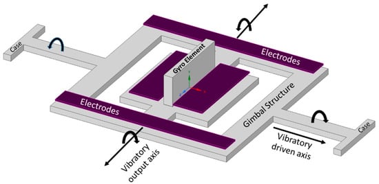
[22]. Boxenhorn et al. demonstrated a first novel micromachined gyroscope in which there was no rotating part. The gyroscope structure was constructed on two gimbal systems: one was outer, and the other was an inner gimbal. A vertical bar was mounted on the inner gimbal. The inner gimbal constituted the sensitive element, while the outer gimbal was attached to a motor. Both gimbals were connected via orthogonal flexural pivots; the outer gimbal was used to vibrate on the given frequency and made the inner gimbal sensitive enough to detect the rotational motion on any external rotation. Furthermore, they fabricated a silicon monolithic micromechanical gyroscope. All of the design features were fabricated on the same substrate, which was the initiation of the mass production of this small-sized vibrating gyroscope. The dimensions of the gimbal structure were 350 µm × 500 µm. The outer gimbal was driven electrostatically by the electrodes at a given amplitude. This movement was transferred to the inner gimbal, making the inertial element oscillate. When rotation was applied to the gyroscope, the Coriolis force shifted the inner gimbal oscillation towards the weak axis with an equal amplitude of driving frequency. The output motion of the inner gimbal was sensed capacitively by the sensing electrodes placed near the gimbal structure. A schematic diagram of a micromachined gimbal gyroscope is shown in
Figure 1 [23].
Figure 1. Schematic diagram of Draper laboratory’s micromachined gimbal gyroscope.
In 1996, the Draper laboratory developed the third phase of design of the vibrating wheel on the gimbal (VWOG) gyroscope. The concept had a vibrating wheel, approximately 1 mm in diameter, at a given resonance. The whole structure was suspended on a Pyrex substrate. The outer ring of the wheel structure was considered a proof mass, and there were fixed stator combs attached to the substrate and a number of combs attached to the wheel. The wheel structure had four beams suspended over the substrate and was centrally anchored to the substrate. The wheel structure was surrounded by the electrodes and those electrodes were used to excite the ring of the wheel. During operation, the wheel vibrated sinusoidally by applying a driving voltage to the fixed stator combs. When the rotation was applied to the gyroscope, the Coriolis force shifted the driving motion to the output axis. This movement was detected by the capacitor pick-off plates placed under the wheel structure and on the Pyrex substrate. The design showed excellent prospects regarding sensitivity, and the sensitivity rate was better than 0.1 deg/s in a 60 Hz bandwidth
[24] in comparison with the Draper laboratory’s tuning fork gyroscope
[25].
Geiger et al. demonstrated a new high-performance, low-cost, rotational rate micromachined gyroscope
[26]. The concept of this gyroscope was on the mixture of the dual gimbal and comb structure gyroscope for primary and secondary oscillation. The gyroscope showed some promising test results, as the angle random walk (ARW) was measured as low as 0.14 deg/h, and the bias stability was recorded at 65 deg/h. The device structure was composed of comb drives, four fixed comb electrodes, a secondary oscillator, and the detection electrodes placed above the substrate. The comb drives were used to provide rotary motion along the
z-axis by electrostatic actuation. The other fixed comb electrodes sensed the primary rotary motion. The Coriolis force was produced when the device rotated along the
x-axis. The Coriolis force was used to create another rotary motion along the
y-axis; hence, the secondary oscillator structure moved with the Coriolis force. The movement was sensed capacitively by the detection electrodes placed above the substrate.
A MEMS gyroscope was created with two gimbal structures, an inner gimbal and an outer gimbal, and was able to operate at atmospheric pressure
[27]. Both the inner and outer gimbals were aligned with inner and outer coils, respectively. The whole gimbal structure was supported by torsional bars, which were placed perpendicularly to the gimbal structure. The current-carrying inner coils oscillated the inner gimbal at the given resonant frequency around the torsion bars. The outer gimbal was in a steady state because the inner gimbal oscillation was parallel to the torsion bars of the outer gimbal. The Coriolis force was generated at the center of the mass when the angular rate was applied perpendicularly. The Coriolis force was used to start oscillating the outer gimbal; subsequently, the outer coils provided an electromotive force for detecting the voltages.
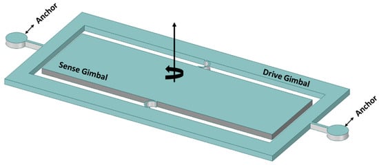
The two gimbal MEMS gyroscope structures containing Ni–Fe alloy were fabricated using the SU-8-based UV-LIGA process
[28]. The authors claimed to overcome the shortcomings of the micromachining process using this process. Initially, a nickel layer of 8 µm was deposited as a structural layer. However, Ni material is prone to residual stresses, and the developed stresses caused the structural layer to buckle and touch the electrode that was placed beneath the device structure. This structural layer buckling issue caused the device to shorten while touching the bottom electrodes. To resolve this issue, a composition of 70% Ni, 15% Fe, and 10% C-based Ni–Fe alloy was used to avoid the buckling of the structural layer. A schematic diagram of the Ni–Fe gimbal MEMs gyroscope is shown in
Figure 2.
Figure 2. Ni–Fe alloy-based two-gimbal system gyroscope.
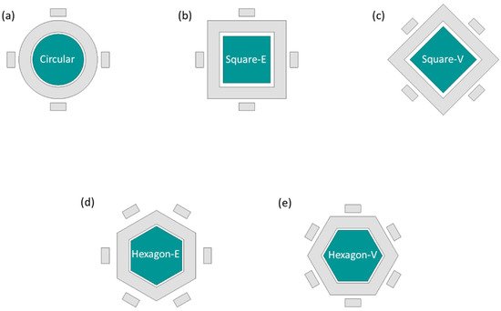
Lee et al. investigated the scale factor and linearity error using various shapes and masses for gimbal gyroscopes
[29]. Different numbers of shapes and masses were considered in this entry, and the designs are shown in
Figure 3. The scale factor and linearity error were extracted by the change in capacitance with various shapes of the gimbal gyroscopes. The different designs showed different results; for example, a circular-shaped structure provides a high scale factor compared to the others. However, the circular shape did not offer a good linearity error. A hexagonal-shaped structure gained the lowest linearity error and reasonable scale factor, making it a more feasible and stable design for MEMS gimbal gyroscopes.
Figure 3. Study of different shapes of an MEMS vibrating wheel on a gimbal gyroscope. (a) circular (b) square-edge (c) square-vertex (d) hexagon-edge (e) hexagon-vertex.
2.2. Tuning Fork Gyroscopes
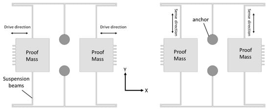
Tuning fork gyroscopes are one of the most popular designs of MEMS gyroscopes. These designs have two identical masses driven with equal amplitude, but in opposite directions
[30]. When the rotational motion comes into place that is perpendicular to the driving axis, this motion produces a Coriolis force that shifts the driving motion towards the sensing axis. The driving and sensing mechanism using electrostatic actuation and capacitive sensing, respectively, provides enhanced sensitivity levels compared to the other designs
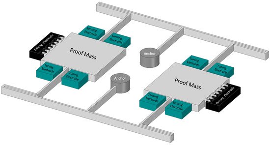
[31]. A schematic illustration of the working operation of the MEMS tuning fork gyroscope is shown in
Figure 4.
Figure 4. Working operation of a basic MEMS tuning fork gyroscope.
In 1993, the first micromachined tuning fork-rate gyroscope was developed using nickel-electroforming technology, reactive ion-etching polysilicon, and single-crystal silicon on glass technology. The size of the gyroscope was 1 mm, and the target was to achieve the bias stability of less than 100 deg/h. Initially, all three fabrication technologies were considered; however, only one was eventually selected because of its good fabrication results. Nickel-electroforming technology reduced the feature size to 6 µm, but due to the low quality and possible fatigue associated with the nickel material, it was dropped because of buckling and fatigue issues. Silicon on glass fabrication offered a very low stray capacitance, but it was limited with symmetric bond wires. Reactive ion etching with polysilicon material offered great properties such as a low corrosion rate and good thermal stability, and thus was chosen as the fabrication technology. The tuning fork gyroscope had two proof masses with perforation; both masses were driven on the given resonant frequency, but in opposite directions. When rotation is applied to the gyroscope, one proof mass goes up and the other goes down. The sensing electrodes placed beneath the proof masses capacitively sensed the change in displacement. The scale factor of 90 mV/deg/s was achieved. The resolution was 0.1 deg/s and the bias stability was 0.2 deg/s in a 1 Hz bandwidth.
Che et al. fabricated a novel tuning fork gyroscope using silicon bonding and deep reactive ion-etching (DRIE) technology
[32]. The gyroscope had two symmetric proof masses with multiple driving and sensing bars. The complete design structure was supported by four anchors connected with spring beams placed on the glass substrate. The gyroscope operated electrostatically and the rotational motion was capacitively sensed at atmospheric pressure. The gyroscope was tested and a significant mode mismatch of 0.12 kHz was observed between the driving and sensing modes. The driving frequency was about 2.87 kHz, the sensing frequency was 2.99 kHz, and the quality factors were 804 and 789 for driving and sensing frequency, respectively.
A high-quality, high-resolution MEMS single-crystal silicon on an insulator tuning fork gyroscope was demonstrated in
[33]. The gyroscope had two proof masses that actuate electrostatically by driving electrodes at a given resonant frequency along the
x-axis. The Coriolis force was induced when the device experienced rotational motion around the
z-axis, and this rotation was sensed capacitively by sensing electrodes along the
y-axis. A schematic view of the high-quality MEMS tuning fork gyroscope is shown in
Figure 5. This design achieved high-quality factors of 81,000 for the driving mode and 64,000 for the sensing mode. The gyroscope structure was fabricated on a 40 µm single silicon crystal on an insulator wafer. The simplest two-mask process was adopted for the fabrication of the gyroscope. The structural layer of moving objects and comb electrodes were first released from the backside of the wafer by etching the silicon layer using the Bosch process. Reactive ion etching was used to remove the buried oxide layer, and then the patterned layer remained to carry the suspended structure. The gyroscope achieved high resolution by electrostatically balancing the driving and sensing modes by tuning the electrodes and achieving high-quality factors with a sensitivity of 1.25 mV/deg/s.
Figure 5. Schematic diagram of high Q MEMS tuning fork gyroscope.
A
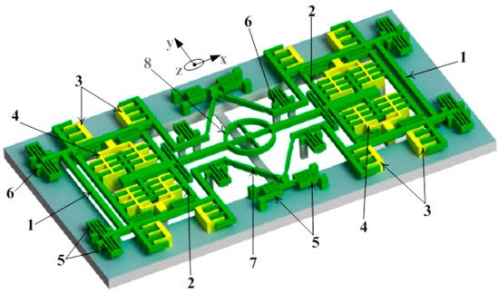
z-axis MEMS tuning fork gyroscope that had a freestanding structure with low-air damping was developed by Nguyen et al.
[34]. There were various factors considered to improve the overall performance of the gyroscope, such as eliminating the squeeze film damping by designing the driving and sensing structure to vibrate in-plane and the removal of the substrate beneath the gyroscope structure to nullify the side-film air damping. The proposed gyroscope is shown in
Figure 6. The simulated driving and sensing frequencies were 9.78 kHz and 9.76 kHz, respectively. The quality factor was measured at 111.2 and the sensitivity of the gyroscope at atmospheric conditions was measured to be 11.56 mV/deg/s.
Figure 6. Schematic representation of the
z-axis freestanding gyroscope
[34]: 1—External frame, 2—internal frame, 3—drive electrodes, 4—sense electrode, 5—spring beams, 6—support anchors, 7—linear beams, and 8—circular rotating ring.
Guan et al.
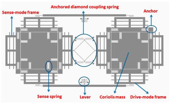
[35] presented a paper on a new MEMS tuning fork gyroscope with anchored coupling. The new design helped to analyze the vibration mode order and the gyroscopic sensitivity. The tuning fork gyroscope utilized a levered system for drive-mode frequency and an anchored coupling spring with four beams for the sensing mode frequency. The simulated sensing frequencies recorded for the in-phase and anti-phase were 4006 kHz and 4464 kHz, respectively. However, the in-phase frequency with anchored coupling was 5958 kHz, which is almost 50% more than the simulated in-phase sensing frequency. The same researchers extended their work
[36] and proposed a new design for an MEMS tuning fork gyroscope with an anchored diamond coupling method, which is shown in
Figure 7.
Figure 7. Schematic view of tuning fork gyroscope with anchored diamond coupling method
[36].
Trusov et al. reported a high-Q tuning fork gyroscope with a rate-integrating method, and the gyroscope demonstrated quality factors for the driving and sensing modes of 310 k and 640 k, respectively
[37].
2.3. Vibrating Ring Gyroscopes
Vibrating ring gyroscopes have a symmetrical structure and provide many advantages over other gyroscope designs. They possess high precision, high resolution, better thermal stability, better matching of operating frequencies, a low zero-output rate, and increased sensitivity
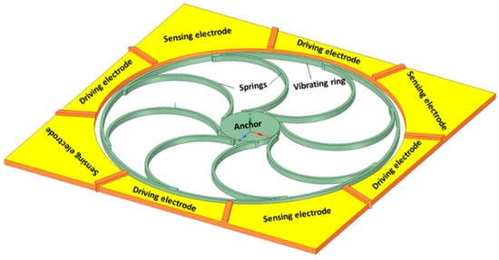
[38]. The basic design of the MEMS vibrating ring gyroscope is shown in
Figure 8. It consists of an outer ring with eight springs that are supported by a circular anchor placed in the middle.
Figure 8. Schematic representation of the basic design of a vibrating ring gyroscope.
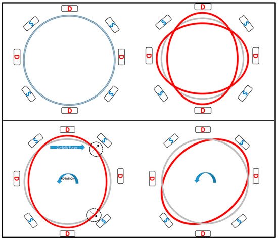
The working operation of a vibrating ring gyroscope is illustrated in Figure 9. The gyroscope’s vibrating structure is surrounded by eight driving and sensing electrodes. The driving electrodes provide a continuous oscillation in the direction of the driving axis. The movement of the ring is clearly visible in the driving direction. However, there is no movement present along the sensing electrodes. When the gyroscope is exposed to external rotation, the elliptical shape of the vibration mode now transfers to the sensing electrodes. When the rotation is applied to the device, the primary vibration induces a secondary vibration mode in the sensing direction because of the generated Coriolis force. The sensing electrodes sense the change of displacement.
Figure 9. Schematic demonstration of the operation of a vibrating ring gyroscope.
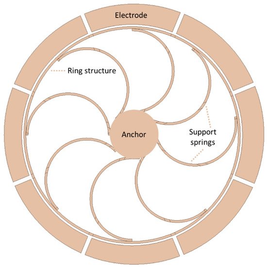
The General Motors Corporation invented a vibrating ring gyroscope
[39]. The ring structure was considered a vibrating element with high-quality radial vibrations. The ring structure was designed to be electrically conductive. There were several electrodes placed around the ring structure for the driving and sensing mechanism, as shown in the schematic diagram in
Figure 10. The ring structure was supported by a centrally placed supported pillar and the ring structure was actuated by electrostatic driving electrodes. When rotation was introduced to the structure, the energy of the first vibration mode was forced to move towards 45 degrees from its position, and the sensing electrodes that were placed at 45 degrees along with the driving electrodes sensed this capacitive movement of the vibrating ring.
Figure 10. Schematic view of a novel vibrating ring gyroscope developed by General Motors.
In 1998, a research group at the University of Michigan reported the first development of a micromachined polysilicon vibrating ring gyroscope
[40]. The ring structure was 30 to 40 µm thick, while the gap between the ring and the electrode was 0.9 µm. Due to the symmetric design, the driving and sensing frequencies were almost identical, resulting in high sensitivity. The same researchers
[41] presented a thorough study on vibrating ring gyroscopes for scale limits and combined microfabrication technologies such as bulk and surface micromachining. A 30 µm structural layer of the vibrating ring gyroscope was fabricated using polysilicon trench-refilling microfabrication technology, with a ring-to-electrode gap of 0.9 µm. The ARW was recorded as low as 0.05 deg/
h−−√, and the overall sensitivity and performance level increased tremendously. There were multiple reasons for achieving the high performance of the vibrating ring gyroscope, such as polysilicon material wafer selection, less of a gap between the ring and electrode, high-quality factors, and dry-etching fabrication technology.
The same research group
[42] presented a high aspect ratio polysilicon vibrating ring gyroscope fabricated using dry-release microfabrication technology. The vibrating ring gyroscope structure’s height was 80 µm. The benefit of dry-release technology was the use of a single wafer process and patterning the electrically isolated electrodes as tall as the ring structure. The sensitivity of the vibrating ring gyroscope was measured as 200 µV/deg/s within the dynamic range of ±250 deg/s under a low vacuum. The quality factor was recorded as 1200, and the driving amplitude was measured at 0.15 µm with 2 pF parasitic capacitance at the sense node.
A high-performance vibrating ring gyroscope was fabricated using the (111) orientation of a single-crystal silicon wafer. The vibrating ring structure of single-crystal silicon was patterned on a glass substrate with a high aspect ratio
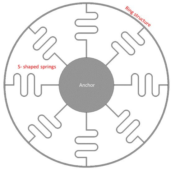
[43]. The ring radius was 1.35 mm and the thickness of the structural layer was 150 µm. The DRIE process patterned and etched a 480 µm (111) silicon wafer. The ring and electrode structure were etched to 150 µm. The wafer was further etched from the backside to release the structure layer by reactive-ion etching. The tested gyroscope achieved a quality factor of 12,000, and nonlinearity was measured at 0.02%, with higher sensitivity of 132 mv/deg/s with high resolution. The new S-shaped support springs vibrating ring gyroscope was presented by Kou et al.
[44]. A ring structure was supported by eight S-shaped symmetrical support springs with centrally anchored support from the circular pillar, as shown in
Figure 11. The ring structure was actuated electrostatically by driving electrodes and the rotational motion was sensed by the sensing electrodes. The whole gyroscopic structure was fabricated using a high aspect ratio microfabrication process. The gyroscope was characterized at atmospheric pressure to evaluate the overall gyroscopic performance. The operational resonant frequencies were measured at 9.844 kHz for driving and 9.865 kHz for sensing. The quality factors were 186 and 163 for driving and sensing, respectively. The zero-bias instability was recorded at 0.017 deg/s and ARW recorded 0.14 deg/
h−−√.
Figure 11. Schematic view of eight S-shaped support springs in a vibrating ring gyroscope.
Kou et al. further elaborated upon their work and carried out a further investigation on the solid-wave vibrating ring gyroscope to increase the sensitivity level
[45]. A solid-wave gyroscope has many advantages, such as good reliability, wide dynamic range, and higher mechanical sensitivity. An exhaustive finite element analysis was conducted to design the gyroscope and simulate the resonant frequency and sensitivity analysis. The relationship between the design parameters and the numerical model of the sensitivity were thoroughly analyzed. The designed resonant frequency was recorded at 6.04 kHz, and the mechanical sensitivity was measured to be 0.0036 µm/deg/s.
Syed et al.
[46] presented a case of design migration for an MEMS vibrating ring gyroscope from a multi-stage complex fabrication process to a simple, cost-effective process. The two different design approaches were considered for the MEMS vibrating ring gyroscope. In the first design, the multi-vibrating ring structure had C-shaped support springs connected and was also supported by the inner anchor. However, in the second design, the multi-vibrating rings with C-shaped support springs were connected and supported with the outer-placed anchor. In the first design, there were some design fabrication limitations to filling the whole area; therefore, the area was filled with more pillars. The second design provided better results for gyroscopic operation. The second design achieved better sensitivity, an easy microfabrication process, perfect wine glass vibration modes, and high shock resistibility.
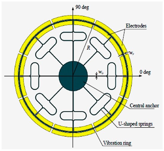
A double U-beam vibrating ring gyroscope was established by Cao et al.
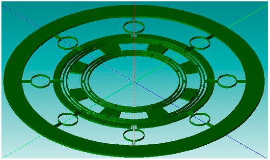
[47]. The design of the device was conceptualized with a mathematical model and finite element modeling. The gyroscope structure comprises a circular ring connected to eight double U-beam support springs, connected with a centrally placed anchor. There were twenty-four electrodes placed around the ring structure to vibrate the ring with driving electrodes and to sense changes in the capacitance due to changes in displacement by sensing electrodes. A schematic diagram of a double U-beam vibrating ring gyroscope is shown in
Figure 12. The microfabrication was done with silicon on glass technology with deep reactive-ion etching. The designed, simulated resonant frequencies for driving and sensing were 9.609 kHz and 9.615 kHz, respectively. The gyroscope was tested for actual performance; the tested resonant frequencies for driving and sensing were 9.124 kHz and 9.146 kHz, respectively, which were lower in comparison to the simulated frequencies. The bias instability was measured to be 8.86 deg/h and the ARW was 0.78 deg/
h−−√.
Figure 12. Schematic view of MEMS double U-beam vibrating ring gyroscope
[47].
A novel design of a multi-ring vibrating gyroscope was established in
[48]. The design had two sets of ring structures: internal rings and external rings. The multiple rings enhanced the sensitivity. The ring structure with C-shaped support springs was connected to the outer-placed fixed anchor. The proposed design of the multi-ring vibrating gyroscope is shown in
Figure 13. The simulated resonant frequency was 40.40 kHz. However, when the device was characterized, the measured resonant frequency was 36.67 kHz. The difference between the designed and tested resonant values was less than 4.0 kHz. The reason for the discrepancy was microfabrication errors such as critical dimension losses and sidewall angle.
Figure 13. Design of a multi-ring vibrating gyroscope
[48].
Liang et al.
[49] developed a MEMS vibrating ring gyroscope that was attached to piezoelectric film. The piezoelectric film covered the circumference of the vibrating ring to adjust the rigidity of the gyroscope. The proposed piezoelectric film enhances the sensitivity because of the control of the forced oscillation and parametric resonance. The increment of the bias voltage and piezoelectric voltage can amplify the driving amplitude response of the gyroscope. Because of the forced oscillation, the sensing amplitude response is more significant due to the forced oscillation speed. When the oscillation speed is decreased, it will affect the other parameters. The best way to achieve maximum sensitivity is to design the gyroscope oscillation speed close to the optimum values. The same research group
[50] further studied the nonlinearity behavior of the vibrating ring gyroscope. The findings were obtained using the nonlinear model to identify the couplings with geometric and structural coupling. It was found that cubic rigidity nonlinearity has a significant impact on the driving and sensing mode coupling.
2.4. Multi-Axis Gyroscopes
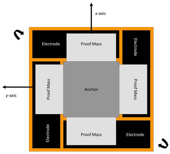
A novel two-dimensional micromechanical gyroscope was developed by Fujita et al.
[51]. The novel design, which is shown in
Figure 14, included four cantilever plates that were placed above the glass substrate with four fixed electrodes. When rotation was applied to the micro gyroscope, the movement was triggered by the Coriolis force and was detected capacitively upon the displacement changing between the cantilever and the fixed electrodes. They proposed to match the driving and sensing frequency for the overall enhancement of the sensitivity of the gyroscope. The sensitivity recorded for this two-dimensional gyroscope was 0.1 mV/deg/s.
Figure 14. Schematic diagram of novel two-dimensional micromachined gyroscope developed by Fujita et al.
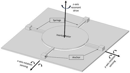
In 1997, a dual-axis micromachined rate gyroscope was presented at the IEEE Transducers 97 Conference
[52]. The gyroscope had a 2 µm thick polysilicon disk of 0.3 mm diameter placed 1.6 µm above the substrate. The disk structure was supported by four beams that were connected with four anchors to support the disk structure. The beams were designed to provide torsional suspension. The device operation had an angular resonant about the
z-axis and the rotation on the
x-axis produced a Coriolis response to the
y-axis. Because of the symmetric structure of the gyroscope, any rotation on the
y-axis produced a Coriolis response on the
x-axis. This change was sensed capacitively by the sensing electrodes placed under the disk structure. A schematic representation is shown in
Figure 15. The ARW was considerably higher due to the mismatch of the resonant frequencies and the tuning frequencies, and the ARW decreased to 2 deg/
h−−√ from 10 deg/
h−−√, but with high cross-axis sensitivity.
Figure 15. Schematic diagram of a dual-axis micromachined vibrating gyroscope.
The NASA Jet Propulsion Laboratory presented its work on the fabrication, design, and packaging of the micro gyroscope for space applications
[53]. The micro gyroscope had a 7 Hz split frequency between the driving and sensing mode, the scale factor was 24 mV/deg/s, the bias stability was 70 deg/h, and the ARW was 6.3 deg/
h−−√. The whole package consisted of the micro gyroscope, preamplifier, power converter, and summation circuit.
In 1998, a tunable micromachined gyroscope was presented by Kang et al.
[54]. The device had a polysilicon structure, two suspended micro plates vibrated electrostatically by a comb structure in the antisymmetric direction, and the two electrodes were placed under the structure of the plates. When the external rotation was applied to the device, the Coriolis acceleration developed and forced the plates to move in the opposite direction or away from the bottom electrodes. This change in capacitance was sensed by the bottom electrodes.
A research group at the University of California developed a four-mass rate-integrated MEMS gyroscope. The proposed design of a four-mass gyroscope offers a dynamically balanced and highly symmetric structure. This vacuum-sealed quadruple-mass gyroscope achieved high quality factors of more than a million in driving and sensing directions. The gyroscope operated at the resonant frequency of 2 kHz. The gyroscope operated with mode matching and showed a linear response in a ±450 deg/s range and 100 Hz bandwidth
[55][56]. Zotov et al. presented the first mechanical frequency-modulated angular rate gyroscope. The reported gyroscope is based on a four-mass gyroscope with a symmetrical structure on the
X-
Y axis. The high-range angular rate sensor was digitally tested by implementing a two-phase locked loop. The device maintained quality factors of more than a million in the driving and sensing direction, with a temperature range from −40 °C to 100 °C
[57].
Senkal et al.
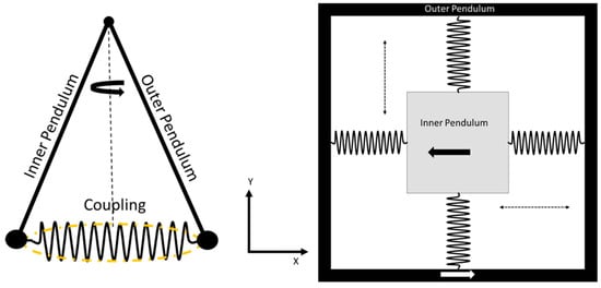
[19] reported a dual mass whole-angle MEMS gyroscope that was based on the dual Foucault pendulum concept. A schematic representation of the reported gyroscope is shown in
Figure 16. The gyroscope has a symmetric design on the
X-
Y axis. The dual-axis gyroscope operated at the frequency of 2.7 kHz with more than 100 k quality factors in both driving and sensing modes. Minotti et al.
[58] developed a three-axis frequency-modulated MEMS gyroscope. The yaw and pitch rates were demonstrated by coupling with two MEMS structures that were fabricated using a 24 µm structural layer process. The devices have shown a stable high scale factor.
Figure 16. Schematic diagram of dual Foucault pendulum gyroscope. Two Foucault pendulums vibrate in antiphase motion.
