Your browser does not fully support modern features. Please upgrade for a smoother experience.
Please note this is an old version of this entry, which may differ significantly from the current revision.
Subjects:
Engineering, Electrical & Electronic
Marine energy resources could be crucial in meeting the increased demand for clean electricity. To enable the use of marine energy resources, developing efficient and durable offshore electrical systems is vital. A DC collection grid can be especially suitable for offshore marine energy resources, since the transmission losses are expected to be lower, and the electrical components could possibly be made smaller. Therefore, five DC collection grid topologies are proposed and qualitatively evaluated for marine energy resources using submerged and non-submerged marine energy converters.
- AC and DC collection grids
- offshore renewable energy
- electrical systems
1. Introduction
The global demand for clean and sustainable electricity is growing. As a result, the proportion of renewable energy sources in the grid is increasing. However, the supply of clean electricity cannot keep up with the demand [1]. Marine energy resources, such as wave power and marine current power, can play a crucial role in increasing the level of clean energy in the grid [2]. A necessary requirement for accessing offshore energy resources is an effective and reliable electrical system. As of now, no large farms with either wave power or marine current power have been constructed, and the question of how the electrical system should be constructed for these technologies is still very much not settled.
A natural point to start investigating suitable electrical systems for marine energy resources is to draw on experiences from offshore wind power. How to construct the internal collection grid in a wind farm and how to transmit the power to the shore have been extensively investigated for offshore wind power [3,4,5]. It can be observed that, in early projects, such as Horns Rev in Denmark, both the internal grid in the farm and the transmission to the shore were constructed using AC [6]. However, in recently completed large wind farms located far from the shore, it has been necessary to use high-voltage DC for the transmission of power to the shore [7]. The internal grid in the farms is, however, still based on AC voltage.
The use of DC, not only for transmission to the shore, but also for the internal collection grid, has attracted increasing attention. For wind power, multiple studies have been carried out on the subject and various topologies have been proposed. A feasibility analysis in [8] proposed four different DC collection grid topologies and showed that they had comparable capital costs to conventional AC collection grids. In [9], a series DC collection grid comprising an AC/AC converter, a high-frequency (HF) transformer and a diode bridge rectifier was proposed. The topology was improved in [10,11] by comparing the losses and improving the efficiency by utilizing different power converters and increasing the operating frequency of the transformers. A review paper compared string, cluster and series DC collection topology with conventional AC for offshore wind [12]. Research regarding offshore DC collection grids has primarily been focused on offshore wind applications, and has not often been expanded to marine energy in general.
2. Marine Energy Resources
The term marine energy resource includes wave power and marine current power. The estimated potential of wave energy worldwide is 32 PWh/year [18]. The worldwide potential of marine current power has not been investigated to the same extent; however, one study [18] stated that the worldwide potential of marine current power is around 3 TW [18]. Only a fraction of this is, however, predicted to be utilizable with regards to the technical limitations of accessing the location of the marine currents. Even though the potential of marine energy worldwide is great, the installed generation capacity is only around 500 MW worldwide, of which tidal range generation constitutes about 99% [18].
3. AC or DC Transmission in Offshore Applications
To avoid high losses and excessively high current ratings of equipment, large offshore energy farms transmit the generated electrical power to the shore using high-voltage alternating current (HVAC) or high-voltage direct current (HVDC) [55]. In the early large-scale offshore wind power farms, HVAC was used for transmission. However, as both the size of the farms and the distances to the shore have increased, the number of projects using HVDC technology has also increased [6,56].
The reason for using HVAC is mainly due to the possibility of utilizing standard transformers to change the voltage levels and the simple design of protection systems compared with HVDC [57]. HVAC has been used for a long time and is considered a matured technology with a high degree of standardization, which makes the availability of components higher than that for HVDC.
There are mainly two different technologies used for HVDC transmission: line-commutated converter (LCC) HVDC and voltage-source converter (VSC) HVDC. LCC HVDC is based on thyristors as switching elements and can only transfer power between two or more active grids, and would, therefore, need an auxiliary start-up system for marine energy applications [58]. LCC HVDC might be less expensive for power ratings of hundreds of megawatts [6], though it is deemed not suitable for offshore applications due to the high space requirements and susceptibility to AC network disturbances [55]. VSC HVDC has lower space requirements and does not need a separate start-up system, which makes it more suitable for offshore applications [56].
Limitations of HVAC
In submarine HVAC cables, the capacitance is high, which results in both resonance issues and reduced power transmission capacity due to the high charging current. Long cables with high charging current can be compensated using, for example, Static VAR-compensators, which is a difficult and costly task [59]. Ideally, compensation is installed at several points along the cable, but practical limitations often result in possible installation only at the receiving or sending end of the cable. In HVDC cables, there is no or very low charging current, which both reduces losses and voltage drop, but also increases the amount of transferrable power compared with HVAC and eliminates the need for costly compensation units.
An AC system that is synchronously coupled to the grid may experience propagating faults. A fault in one part of the grid will propagate to other parts of the grid. In DC grids, the energy converters will not have a significant impact on the short-circuit current in the main AC grid, since they are not synchronously coupled [60]. Another benefit of HVDC is that, if HVDC is used together with a voltage source converter technology, it is possible to provide ancillary services to the main AC grid through fast control of active and reactive power and frequency response [61].
One disadvantage of HVDC transmission is that HVDC requires more power electronic components compared with traditional HVAC transmission technology, which increases the investment cost. AC/DC and DC/AC converter stations are also costly, which leads to HVDC systems having a higher fixed cost associated with station infrastructure than HVAC [56]. The marginal cost per km of transmission is lower for HVDC, because it requires less cable material and exhibits lower power losses.
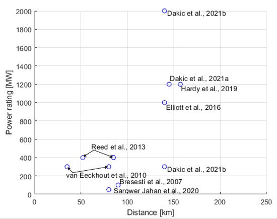
As HVDC has higher fixed costs, but lower marginal costs; at a certain distance, HVDC transmission will be the less expensive option compared with HVAC [62]. At what distance the cost for DC transmission and AC transmission is equal has been assessed in multiple studies. Studies discussed in [63] and [3], for example, suggested a break-even distance of 30–50 km, while a techno-economical study in [6] showed that, for a 100 MW wind farm, the break-even distance is 90 km. In [64], the break-even distance for a farm of 1 GW was estimated to be 120–160 km. The aforementioned studies and [65,66,67,68,69] are summarized in Figure 18. At what distance cost parity between HVDC and HVAC transmission occurs depends on factors such as the need for reactive compensation, voltage levels and right of way, and will be more or less unique for every project.
4. Collection Grids for Marine Energy Resources
In this section, five different DC collection grid topologies, based on the DC collection grids and energy conversion topologies presented, are discussed from the perspective of marine energy converters. Factors such as size, cost and losses are considered. The topologies are evaluated from the perspective of marine energy converters that are either submerged or placed on a platform or floating. The considered topologies are presented below.
Topology 1 (T1) is a parallel-connected DC collection grid without separate boosting steps. This is the topology illustrated in Figure 19. The dashed box is used to indicate the marine energy converter.
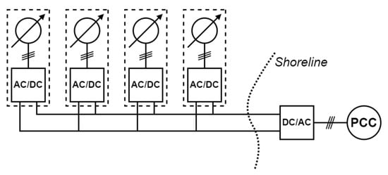
Figure 19. Topology T1. A parallel-connected DC collection grid without separate boosting steps.
Topology 2 (T2) is also a parallel-connected DC grid. However, an additional DC/DC conversion step is included in the marine energy converter. This topology is illustrated in Figure 20.
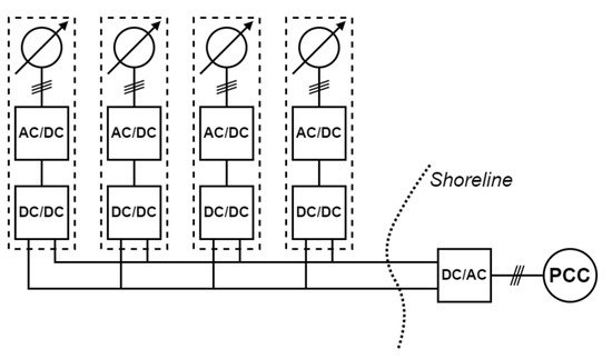
Figure 20. Topology T2. A parallel-connected DC collection grid with a separate boosting step in the marine energy converter.
In the third case, Topology 3 (T3), the aggregation of power from the WECs is conducted after the rectification in the marine energy converter at a central offshore DC/DC converter. This converter could, for example, be submerged or placed on a floating structure. The third topology is illustrated in Figure 21.
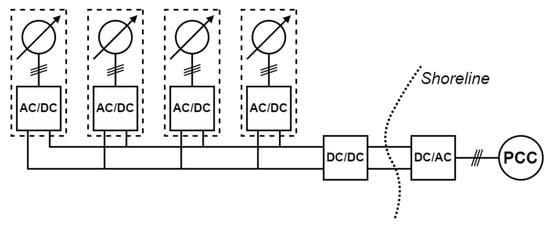
Figure 21. Topology T3. A parallel-connected DC collection grid with rectification in the marine energy converters and DC/DC conversion in a central offshore hub.
In Topology 4 (T4), a transformer is included directly after the generator, and the AC voltage from the transformer is rectified [70]. This allows the voltage to be increased closer to the generator and the DC/DC converter to be omitted. Topology T4 is illustrated in Figure 22.
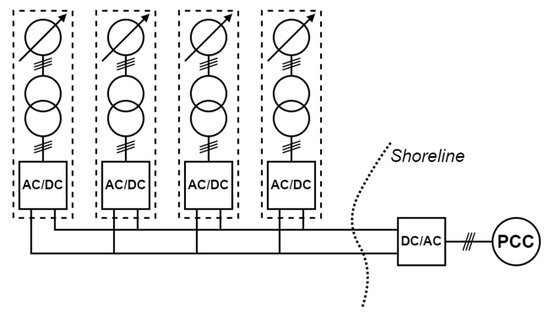
Figure 22. Topology T4. A parallel-connected DC collection grid with a transformer and rectification in the marine energy converters.
In Topology 5 (T5), the marine energy converters are connected in series to a DC collection grid. As discussed in Section 5.2., this enables the transmission voltage to be increased to higher levels without the use of external DC/DC converters. The output voltage from the generator is rectified in the marine energy converter by a single rectifier, and no additional boosting step is utilized. Topology T5 is illustrated in Figure 23.
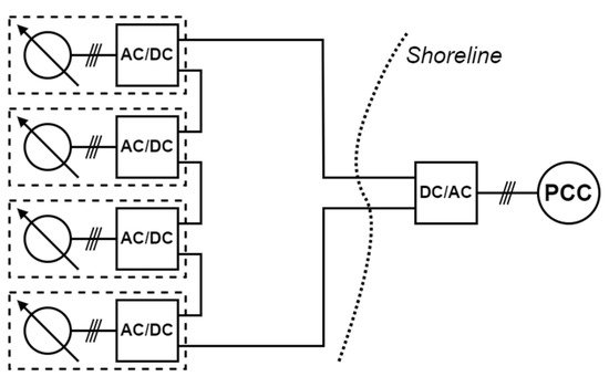
Figure 23. Topology T5. Series-connected DC collection grid with AC/DC conversion in the marine energy converters and no additional DC/DC step.
4.1. Submerged Energy Converter
A submerged marine energy converter would encounter varying differences from a device placed on a platform or floating. One of the significant advantages for all of the five considered topologies in the case of a submerged device is that the device can be moored and allowed to stand on the seabed. This reduces the complexity and cost of platforms or floating structures, which have a very high capital investment [71]. In the case of marine energy resources, it also allows the possibility of exploiting the potential of deep seas with high wave energy availability without significantly increasing the investment cost [72].
The radially connected Topology T1 will probably be one of the least expensive topologies. This is due to an expected lower investment cost, since fewer power electronic converters are required compared with the other topologies. However, due to there being no additional boosting step for the voltage, neither in the marine energy converter nor in an external hub, and the limitation of voltage boosting from an individual marine energy converter using a boost rectifier [37], Topology T1 is expected to have high transmission losses and is limited to near-shore applications.
The disadvantage of the low collection grid and transmission voltage in Topology T1 can be mitigated by adding a DC/DC converter to each marine energy converter. The boosting of the voltage will decrease the collection and transmission losses and enhance the possibility of far-from-shore applications. However, the addition of several DC/DC converters will increase the cost and the number of power electronic components, such as IGBTs and diodes. A system with DC/DC converters will also have significant power losses in the power converters contributable to, for example, switching and conduction losses in the IGBTs. Therefore, the decreased losses for the transmission of power from the marine energy converters to the shore must be weighed against the power losses in the DC/DC converters.
In Topology T3, the investment cost of the system is expected to decrease compared with topology T2. This is because of the reduced cost of only requiring one or a few central DC/DC converters in a hub compared with installing a DC/DC converter in each marine energy converter. Additionally, the individual DC/DC converter must also be rated for a wide spectrum of power levels from a single unit due to varying wave and marine current conditions. On the other hand, the power variability can be decreased with a suitable farm-placement strategy [73]. This reduces the need to rate the DC/DC converter for a wide spectrum of power levels, and hence makes the manufacturing of the component easier and less expensive.
The transmission losses are expected to decrease for Topology T3 compared with Topology T1. However, the technical limitations of the maximum-rated DC/DC converters available on the market limits the rating of the marine energy farm, that is, how many marine energy converters that can be connected to a single DC/DC converter. A medium-frequency (MF) or HF transformer is a core part of an isolated DC/DC converter, for example, a full-bridge converter. The size of the core can be made smaller by increasing the frequency. Since the size of the core can be reduced when the frequency is increased, the smaller core in MF and HF transformers would require less copper wire for the same turns ratio as an LF transformer; therefore, an MF or HF transformer should have lower copper losses [74]. The reduced size of HF or MF transformers also implies that the DC/DC converter could be constructed to be much smaller compared with directly using an LF transformer (compared to Topology T4). This could be a significant advantage in the case of marine energy applications, where space limitation is expected to be a significant constraining factor. However, an MF or HF transformer is expected to have higher eddy current losses [75]. It should also be observed that MF and HF transformers for high-power applications are unconventional designs. Most commonly, transformers are designed for utility grids with a low frequency. Therefore, special attention will be needed when designing a transformer for MF and HF applications [76]. The implication is that, even if the use of a DC/DC converter can contribute to decreasing the size of the marine energy converter and lowering transmission losses, the need for a highly custom-made component can contribute significantly to increasing the investment cost of the system.
Topology T4 utilizes an LF transformer to increase the collection and transmission voltage. This decreases the power losses without the increased complexity of manufacturing DC/DC converters with MF or HF transformers. However, due to the larger size of the LF transformer, the transportation and installation of the marine energy converter at the offshore site are expected to be more complex.
Topology T5 uses the series connection of marine energy converters to increase the transmission voltage, thereby saving the cost of the DC/DC converters or transformers used to increase the voltage for transmission in Topologies T2 and T4, respectively. However, the voltage to the ground for the last marine energy converter device in the series connection will correspond to the total transmission voltage, which can be problematic from the perspective of electrical insulation. To partially overcome this, the ground could be placed in the middle of the series connection to limit the voltage to the ground. Studies have shown that this topology can be preferred for higher-rated wind power generators, where it leads to reduced losses and is possibly economically less expensive [9]. This topology could, therefore, also be preferable for higher-rated marine energy converters.
The submerged system also has a possible advantage with regards to cooling, which applies to all of the topologies discussed above. Seawater can be used as a natural or passive cooling system. The losses in IGBTs and diodes are linearly dependent on the temperature [77]. Hence, the lower temperature of seawater will have a positive effect on the power electronics components leading to lower power losses. This will increase the reliability of the power electronics components and transformer through operation at stable temperatures. It will lead to a decreased need for cooling components and rotating parts, such as fans and heat sinks. The natural cooling system can also reduce the usage of cooling oil, which will be preferred in the offshore environment due to the fear of leakage. Some of the important characteristics of the considered topologies with submerged marine energy converters are summarized in Table 1.
Table 1. Important characteristics for Topologies T1–T5 with a submerged marine energy converter.
| T1 | T2 | T3 | T4 | T5 | |
|---|---|---|---|---|---|
| Size and weight | Size and weight of the devices are flexible due to the use of the seabed as a base. | ||||
| Cost | Cost-efficient. | Cost increases due to multiple DC/DC converters. | Lower cost than topology T2 due to central DC/DC converter. | Similar to T1. | |
| Power losses | Low converter losses, high transmission losses. |
High converter losses, lower transformer losses, lower collection and transmission losses. |
Converter losses similar to Topology T2. | Lower converter losses. | Converter losses similar to Topology T1. |
| Pros | Low cost and mature technology. | Compact converter size and low losses. | Similar to Topology T2. | Reduced converter losses. | Low cost with low transmission losses. |
| Cons | High losses and for limited-rated marine energy farms. | High cost. | Lack of standard DC/DC converters for farms with high power rating. | Deployment complexities due to size | Less reliable and insulation problems. |
4.2. Energy Converter on Platform or Floating
The weight and size of the power electronic components and carrying capacity of the marine energy converter would determine the necessity of using a platform or placing the components with an already floating marine energy converter [71].
Since Topology T1 consists of fewer power electronic components, it can be possible to place the components in the marine energy converters. The deployment and maintenance costs would be expected to decrease due to the easier access to the electrical components compared to the submerged system. The power losses would also increase due to the higher temperature of electronic components on the platform compared with a submerged system. The thermal conductivity of air is less than that of water. This leads to a linear increase in IGBT and diode losses with respect to temperature [77]. Active cooling needs to be provided for this topology [78].
The electrical components in the topologies would be similar to those in the submerged case. Additional components for cooling could be required for the non-submerged case. However, the total cost for the power electronic components is expected to be unchanged compared with the submerged system.
In the case of Topologies T2 and T3, the possibility of making the DC/DC converter smaller and lighter due to the use of MF or HF transformers can increase the possibility of these components being placed on the marine energy converter. However, the floating marine energy converter must be designed with enough carrying capacity and space to handle these components. The cost and power losses would follow the same trend as the submerged marine energy converter. However, since access to the marine energy converter would be easier in the non-submerged case, the maintenance cost can be expected to be lower compared with the submerged case.
A fixed platform structure would probably be necessary with the inclusion of the LF transformer in Topology T4. This increases the cost significantly and limits the placement of marine energy farms up to a certain distance offshore.
The cost, pros and cons of the power converters would remain similar to the submerged case for all of the topologies due to the unchanged electrical network architecture. Maintenance is easier due to the ease in the reachability of the platform compared with the seabed. However, the losses would probably be expected to increase, as explained above. An active cooling method is most likely required due to the placement of electrical components in a dry/semi-dry atmosphere.
Important characteristics of the considered topologies with non-submerged marine energy converters are summarized in Table 2.
Table 2. Important characteristics of Topologies T1–T5 with a non-submerged marine energy converter.
| T1 | T2 | T3 | T4 | T5 | |
|---|---|---|---|---|---|
| Size and weight | Possible to place the power electronics with the marine energy converters. | The compactness of the size and weight of the DC/DC converter due to the MF or HF transformer makes it easier to place. | A platform is necessary with the inclusion of the LF transformer. | Similar to T1. | |
| Cost | Converter cost remains the same. However, the deployment and maintenance cost decreases. | High cost. | Similar to T1. | ||
| Power losses | Losses will increase linearly with an increase in temperature. | ||||
| Pros | Ease of deployment and maintenance. | Ease of deployment compared with submerged. | Similar to T1. | ||
| Cons | Similar to the submerged case. The need for active cooling is, however, increased. | Necessity to construct a fixed platform. | Similar to T1. | ||
This entry is adapted from the peer-reviewed paper 10.3390/en15165816
This entry is offline, you can click here to edit this entry!
