Mechanism of Photocatalytic Water Splitting: History
Please note this is an old version of this entry, which may differ significantly from the current revision.
Contributor: , ,

The constant increase in the amount of energy consumed and environmental problems associated with the use of fossil fuels determine the relevance of the search for alternative and renewable energy sources. One of the most promising renewable fuels is hydrogen gas, which can be produced by sunlight-driven photocatalytic water splitting. The decisive role in the efficiency of the process is played by the properties of the photocatalyst. Oxide materials are widely used as photocatalysts due to their appropriate band structure, high-enough photochemical stability and corrosion resistance. However, the bandgap, crystallinity and the surface morphology of oxide materials are subject to improvement. In order to choose an appropriate oxide semiconductor photocatalytic material and strategies of its modification it is necessary to examine the mechanism of the photocatalytic water splitting.

  • photocatalytic water splitting
  • photoelectrochemical water splitting
  • hydrogen production

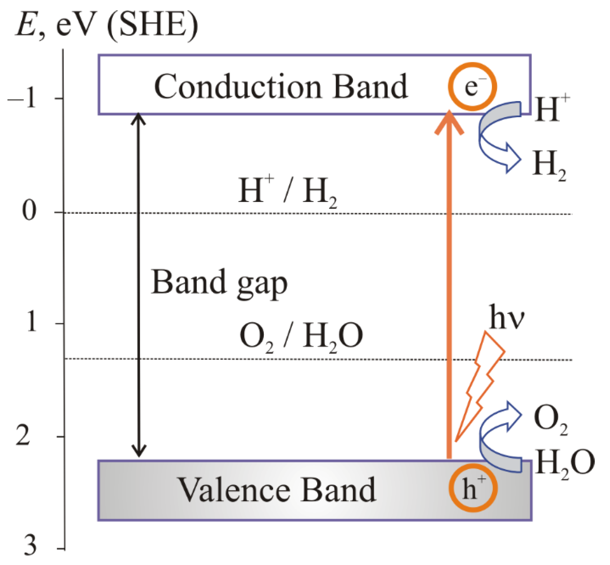
1. The Main Stages of the Photocatalytic Water Splitting

Photocatalysis includes four main stages [1][2]:
the absorption of light by a semiconductor;
excitation of charge carriers;
separation and transfer of charge carriers;
surface catalytic reactions.
The first stage is the irradiation of a semiconductor material with an energy higher or equal to its bandgap.
The absorption of light results in the second stage, which is the photogeneration of the electrons e and holes h+:
Catalyst → Catalyst (e− + h+).
In case of a wide-bandgap semiconductor, the electrons and holes can be generated only in the high-energy ultraviolet (UV) region of the solar spectrum. In a semiconductor with donor- or acceptor-energy levels the bandgap is narrowed. Therefore, in such semiconductors the photogeneration of nonequilibrium charge carriers becomes possible even under visible-light illumination.
The next stage is the separation of electrons and holes between the valence band (VB) and conduction band (CB). The photogenerated electrons transfer to the CB while the photogenerated holes stay in the VB.
Finally, charge carriers take part in surface catalytic reaction. Photogenerated electrons participate in the multistage process of proton reduction to molecular hydrogen:
2H+ + 2e− → H2.
In Process (2), the initial stage, namely the proton adsorption on the active centers of the semiconductor surface, is crucial.
Photogenerated holes are also involved in the reactions. Being powerful oxidizing agents, they can oxidize water and organic substances, such as alcohols:
H2O + 2h+ → 1/2O2 + 2H+,
RCH2OH + 2h+ → RCHO + 2H+.

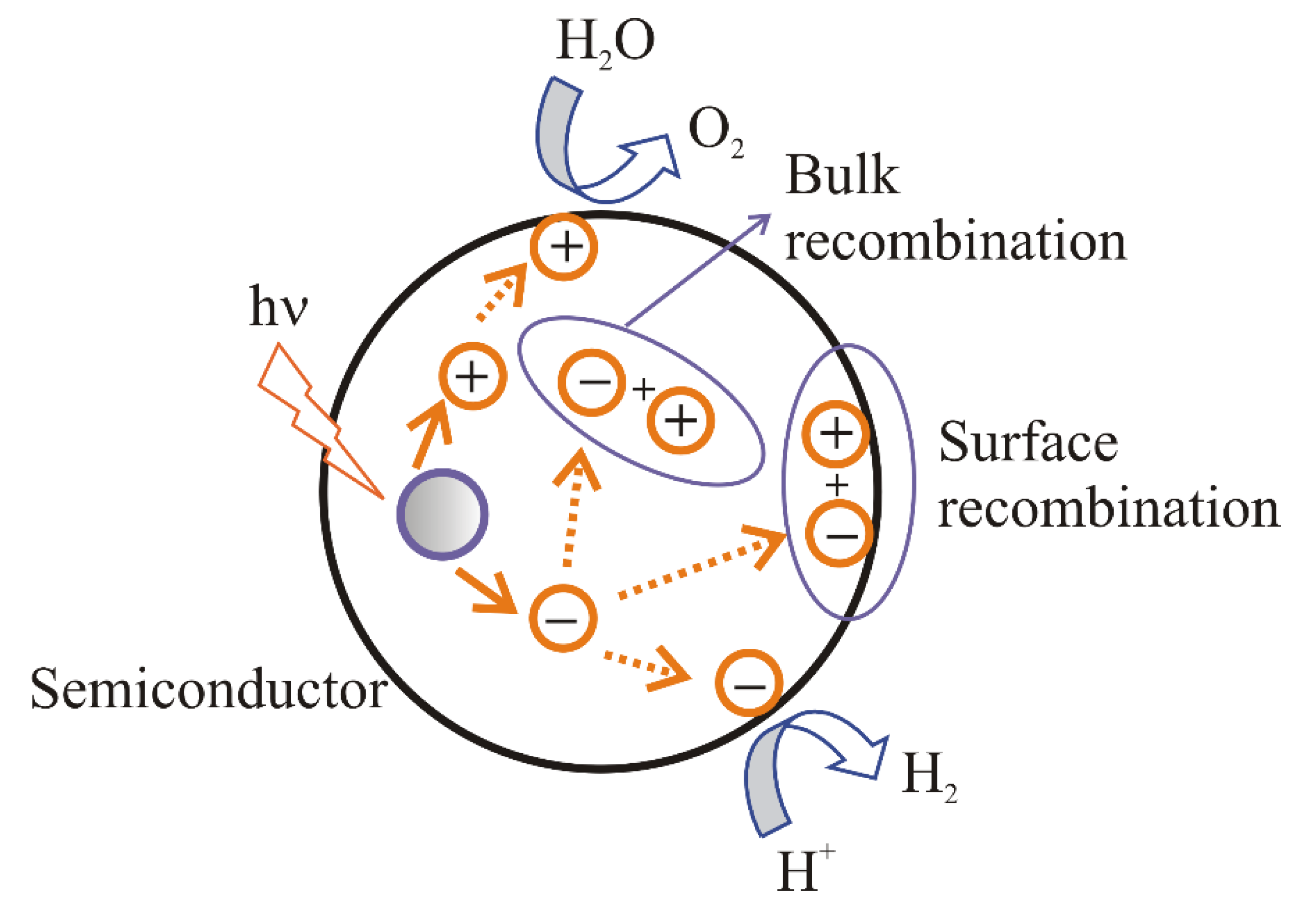
2. The Main Conditions for Water Splitting

In addition to the presence of photoexcited charge carriers, the correct arrangement of band edges relative to Fermi levels of H2O/H2 and O2/H2O systems is necessary:
E F ( O 2 / H 2 O ) = E F ( O 2 / H 2 O )   0   k T ln ( a H + a H + 0 ) 1 4 k T ln ( P O 2 P O 2 0 )   ,
E F ( H 2 O / H 2 ) = E F ( H 2 O / H 2 )   0   k T ln ( a H + a H + 0 ) + 1 2 k T ln ( P H 2 P H 2 0 ) .  
Here, E F ( H 2 O / H 2 ) 0 and E F ( O 2 / H 2 O ) 0 are the standard Fermi levels of H2O/H2 and O2/H2O systems, a H + and a H + 0  are the activity and standard activity of protons in solution, P and P0 are pressure and standard pressure of gases.
To provide the Reaction (2) the upper edge of the valence band must be more positive as compared to the Fermi levels of O2/H2O systems (5) (Figure 1). To provide the reaction (3) the lower edge of the conduction band must be more negative as compared to the Fermi levels of H2O(H+)/H2 systems (6) (Figure 1).
Figure 1. Generation of charge carriers in a semiconductor with band structure providing Processes (2) and (3) [3].
The electric field formed at the interface as a result of achieving thermodynamic equilibrium provides the separation of photoexcited charge carriers [4]. The following ways for the distribution of electrons and holes are possible [1] (Figure 2):
Figure 2. Photogeneration of charge carriers in a semiconductor (SC) and possible ways of their distribution [5].
(i).
recombination of electrons and holes on the surface of a semiconductor;
(ii).
recombination of electrons and holes in the bulk of a semiconductor;
(iii).
transport of the electrons to the surface and participation in the reduction reaction;
(iv).
transport of the holes to the surface and participation in the oxidation reaction.
In cases (a) and (b), Process (1) proceeds in the opposite direction, heat is released, and charge carriers are excluded from further operations. In cases (c) and (d), an electrochemical process is carried out.
The main problem that arises during photocatalytic water splitting is the irreversible recombination of charge carriers with the release of heat. To prevent the recombination, it is necessary to maintain the stability of the separation of charge carriers due to the electric field. For this purpose, photocatalytic water splitting is usually studied in electrolyte solutions (for example, Na2S and KI) in the presence of a sacrificial reagent [6][7][8][9][10]. Some examples of the sacrificial reagents are presented in Table 1.
Table 1. The efficiency of some sacrificial reagents in hydrogen production.
The compounds of the electrolyte do not undergo reduction or oxidation by electrons and holes. However, they provide the transport of ions and electrons, and therefore increase the efficiency of photocatalytic water splitting [1].
The sacrificial substances can accept the holes [6] increasing the hydrogen formation efficiency because of more effective charge separation [11]. Moreover, the sacrificial substances can take part in electrochemical transformations. Alcohols are oxidized based on their standard oxidation potentials, which are lower than that of water [12], and they can participate in the processes of photoreforming into hydrogen and CO2 in the presence of H2O. The effectiveness of the most frequently used sacrificial agents with concentration of 20 vol.% increases in the following order: ethanol < methanol < ethylene glycerol < glycerol [6][8]. In [13], another row was observed for sacrificial agents with concentration of 1000 mg L−1: ethanol < glycerol < glucose < methanol. In accordance with [12], the efficiency of organic compounds depends on the number of hydroxyl groups, which defines the polarity, binding mode on the catalyst, adsorption strength and oxidation potential. In general, the higher the polarity of organic compound, the higher the efficiency of hydrogen evolution. Furthermore, hydrogen production is stimulated in the presence of α-hydrogen atoms in alcohols; therefore, ethanol with fewer carbon atoms attached to α-hydrogen atoms showed less efficient H2 formation as compared to other alcohols.
Apart from the type of sacrificial agent, its concentration influences the rate of the photocatalytic process. In [14], the increase in concentration of trimethylamine from 0.1 to 1.0 mol L−1 was observed to promote proper use of the catalyst active sites for improved mass transfer.
In general, the photocatalytic hydrogen generation increased by growing concentration of sacrificial agent because of its more diffusion [13]. However, this effect is limited by an optimal concentration of the sacrificial reagent. For example, for methanol the maximum efficiency of hydrogen production was observed in 5% solution; a further increase in the concentration does not lead to an increase in the amount of H2 due to the saturation of the photocatalyst surface [6].
The best way to choose an optimum sacrificial agent is to combine the high efficiency, low price, and possibilities of recycling. It is important to note that alcohols such as methanol and ethanol are rather valuable compounds in industry, so their consumption during H2 production can lead to unreasonable costs [15]. Other substances have also been tested including some renewable biomass, organic waste, or pollutants as electron donors, such as glycerol, triethanolamine, and glucose [16]. Their efficiency is less compared with methanol yet. However, utilizing the biomass-derived substances and waste organic materials as sacrificial agents can enhance photocatalytic hydrogen production reducing the costs of the technology, excluding use of valuable alcohols, and ensuring waste recycling.

3. The Mechanism of Photoelectrochemical Water Splitting

Photoelectrochemical (PEC) water splitting can be realized in a photoelectrochemical cell without sacrificial reagents. A voltage bias is an effective way to facilitate electrons and holes’ separation and their transfer during the PEC water-splitting process. [17]. A necessary condition is the excess of the minimum voltage for the decomposition of a compound [18]. For water, it is equal to the difference of potentials corresponding to the Fermi levels of H2O/H2 and O2/H2O systems (5) and (6). The theoretical voltage of water splitting for unity activities and pressures should be at least 1.23 eV:
Δ E = E F ( H 2 O / H 2 ) 0 E F ( O 2 / H 2 O ) 0 = 1.23   eV .
Considering the overvoltage of partial processes (2) and (3), it can reach ~2.3 eV.
The photoelectrochemical cell can be of three types:
a photoanode (n-type semiconductor electrode) and a metal (platinum) cathode (Figure 3a);
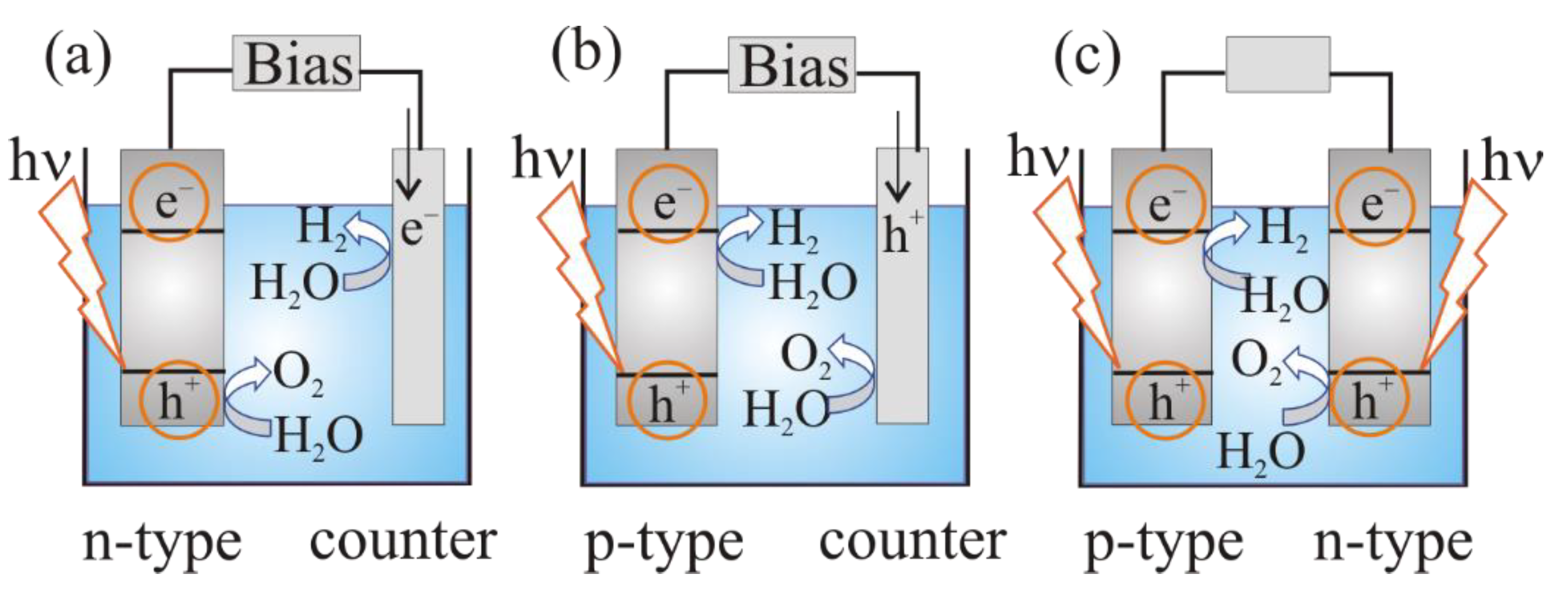
Figure 3. Photoelectrochemical cell for water splitting: (a) n-type semiconducting (SC) photoanode and Pt cathode; (b) p-type semiconducting (SC) photocathode and Pt anode; (c) semiconducting photoanode and photocathode (tandem system) [19].
a photocathode (p-type semiconductor) and a metal (platinum) anode (Figure 3b):
a photoanode (n-type semiconductor electrode) and a photocathode (p-type semiconductor (Figure 3c).
On the first step of the PEC water-splitting process charge carriers of semiconductor electrodes are photogenerated. The solar illumination causes the Fermi level rise in the n-type semiconductor bulk [18]. The flat-band potential Efb corresponds to the maximum Fermi level in the photoelectrochemical cell. Hydrogen can be evolved at the counter electrode only if Efb is above the Fermi level of H+/H2 system. Therefore, an external anodic bias is applied to increase the band bending in the semiconductor to maintain the required charge separation, and also to provide the overvoltage at the metal cathode, which is required to sustain the electric current flow. The further Efb lies below the Fermi level of the H+/H2 system, the greater the bias [18].
After the electron–hole pairs appeared in the n-type photoanode, illuminated with photons with energies higher than the bandgap of the semiconductor, the minority charge carriers (holes) move to the interface and participate in oxidation reaction on the surface of the semiconductor photoanode. The main carriers (electrons) move into the bulk of the semiconductor, then through the external circuit to the counter electrode and participate in reduction reaction with the formation of hydrogen (Figure 3a).
The reduction in protons leads to the formation of hydrogen on a photocathode (p-type semiconductor), whereas on the counter electrode, H2O is oxidized (Figure 3b) [4][20]. In case of a cell constructed of n-type and p-type photoelectrodes (Figure 3c) the simultaneous reduction and oxidation of water molecules can be realized.
Economical hydrogen production requires an efficient interaction between the light, catalyst, and reagents [1]. The most important parameters by which the efficiency of photocatalytic water splitting is estimated include the stability of the photoelectrochemical cell and the rate of production of H2 or O2. There are some  of the main characteristics for the quantitative assessment of photocatalytic water splitting [21]:
1. The turnover frequency (TOF) is the amount of hydrogen nH2, formed per unit of time t per gram of catalyst mSC:
TOF = n H 2 m SC t .
2. The turnover number (TON) is the amount of hydrogen nH2 formed per mole of catalyst nSC:
  TON = n H 2 n SC .
3. The quantum yield (QY) is the ratio of the number of reacted electrons ne, to the number of absorbed photons n ph ads :
QY ( % ) = n e - n ph ads · 100 %   .
4. Apparent quantum yield (AQY) is the ratio of the double amount (mol) of hydrogen nH2 to the number of emitted photons nph:
AQY ( % ) = 2 n H 2 n ph · 100 %   .
The minimum level for commercial application of photocatalytic water splitting is usually considered to be 10% quantum yield, 1000 h of stable operation and high rates of hydrogen and oxygen production [3][17][19][22][23][24]. For the achievement of such characteristics, the potential of the energy level at which holes are located in a semiconductor electrode must be at least 1.6 V [25], and the photocurrent density, measured in a photoelectrochemical cell under illumination, must not be less than 8.2 mA cm−2 [19]. The photocatalyst material plays a decisive role in the achievement of a high efficiency of water splitting.

This entry is adapted from the peer-reviewed paper 10.3390/ma15144915

References

  1. Fajrina, N.; Tahir, M. A critical review in strategies to improve photocatalytic water splitting towards hydrogen production. Int. J. Hydrog. Energy 2019, 44, 540–577.
  2. Wen, J.; Xie, J.; Chen, X.; Li, X. A review on g-C3N4-based photocatalysts. Appl. Surf. Sci. Part B 2017, 391, 72–123.
  3. Chen, J.; Yang, D.; Song, D.; Jiang, J.; Ma, A.; Hu, M.Z.; Ni, C. Recent progress in enhancing solar-to-hydrogen efficiency. J. Power Source 2015, 280, 649–666.
  4. Rongé, J.; Bosserez, T.; Huguenin, L.; Dumortier, M.; Haussener, S.; Martens, J.A. Solar hydrogen reaching maturity. Oil Gas Sci. Technol. Rev. D’ifp Energ. Nouv. 2015, 70, 863–876.
  5. Chen, X.; Shen, S.; Guo, L.; Mao, S.S. Semiconductor-based photocatalytic hydrogen generation. Chem. Rev. 2010, 110, 6503–6570.
  6. Ortega Méndez, J.A.; López, C.R.; Pulido Melián, E.; González Díaz, O.; Doña Rodríguez, J.M.; Fernández Hevia, D.; Macías, M. Production of hydrogen by water photo-splitting over commercial and synthesised Au/TiO2 catalysts. Appl. Catal. B Environ. 2014, 147, 439–452.
  7. Chen, W.-T.; Chan, A.; Al-Azri, Z.H.N.; Dosado, A.G.; Nadeem, M.A.; Sun-Waterhouse, D.; Idriss, H.; Waterhouse, G.I.N. Effect of TiO2 polymorph and alcohol sacrificial agent on the activity of Au/TiO2 photocatalysts for H2 production in alcohole-water mixtures. J. Catal. 2015, 329, 499–513.
  8. Wang, M.; Shen, S.; Li, L.; Tang, Z.; Yang, J. Effects of sacrificial reagents on photocatalytic hydrogen evolution over different photocatalysts. J. Mater. Sci. 2017, 52, 5155–5167.
  9. Tahir, B.; Tahir, M. Morphological effect of 1D/1D In2O3/TiO2 NRs/NWs heterojunction photo-embedded with Cu-NPs for enhanced photocatalytic H2 evolution under visible light. Appl. Surf. Sci. 2020, 506, 145034.
  10. Tahir, B.; Er, P.W.; Tahir, M.; Nawawi, M.G.M.; Siraj, M.; Alias, H.; Fatehmulla, A. Tailoring metal/support interaction in 0D TiO2 NPs/MPs embedded 2D MAX composite with boosted interfacial charge carrier separation for stimulating photocatalytic H2 production. J. Environ. Chem. Eng. 2020, 8, 104529.
  11. Acar, C.; Dincer, I.; Zamfirescu, C. A review on selected heterogeneous photocatalysts for hydrogen production. Int. J. Energy Res. 2014, 38, 1903–1920.
  12. Tasleem, S.; Tahir, M.; Zakaria, Z.Y. Fabricating structured 2D Ti3AlC2 MAX dispersed TiO2 heterostructure with Ni2P as a cocatalyst for efficient photocatalytic H2 production. J. Alloys Compd. 2020, 842, 155752.
  13. Vaiano, V.; Iervolino, G. Visible light driven photocatalytic hydrogen evolution using different sacrificial reagents. Chem. Eng. Trans. 2019, 74, 547–552.
  14. Yang, R.; Song, K.; He, J.; Fan, Y.; Zhu, R. Photocatalytic hydrogen production by RGO/ZnIn2S4 under visible light with simultaneous organic amine degradation. ACS Omega 2019, 4, 11135–11140.
  15. Li, Q.; Li, X.; Yu, J. Surface and interface modification strategies of CdS-based photocatalysts. In Interface Science and Technology, 1st ed.; Yu, J., Jaroniec, M., Jiang, C., Eds.; Elsevier: Amsterdam, The Netherlands, 2020; Volume 31, pp. 313–348.
  16. Zhao, W.; Ma, W.H.; Chen, C.C.; Zhao, J.C.; Shuai, Z.G. Efficient degradation of toxic organic pollutants with Ni2O3/TiO2−xBx under visible irradiation. J. Am. Chem. Soc. 2004, 126, e4783.
  17. Fang, Y.; Hou, Y.; Fu, X.; Wang, X. Semiconducting Polymers for Oxygen Evolution Reaction under Light Illumination. Chem. Rev. 2022, 122, 4204–4256.
  18. Nozik, A.J.; Memming, R. Physical chemistry of semiconductor—Liquid interfaces. J. Phys. Chem. 1996, 100, 13061–13078.
  19. He, H.; Liao, A.; Guo, W.; Luo, W.; Zhou, Y.; Zou, Z. State-of-the-art progress in the use of ternary metal oxides as photoelectrode materials for water splitting and organic synthesis. Nano Today 2019, 28, 100763.
  20. Meng, X.-D.; Wang, D.-Z.; Liu, J.-H.; Zhang, S.-Y. Preparation and characterization of sodium titanate nanowires from brookite nanocrystallites. Mater. Res. Bull. 2004, 39, 2163–2170.
  21. Corredor, J.; Rivero, M.J.; Rangel, C.M.; Gloaguen, F.; Ortiz, I. Comprehensive review and future perspectives on the photocatalytic hydrogen production. J. Chem. Technol. Biotechnol. 2019, 94, 3049–3063.
  22. Grewe, T.; Meggouh, M.; Tüysüz, H. Nanocatalysts for solar water splitting and a perspective on hydrogen economy. Chem. Asian J. 2016, 11, 22–42.
  23. Chen, Z.; Jaramillo, T.F.; Deutsch, T.G.; Kleiman-Shwarsctein, A.; Forman, A.J.; Gaillard, N.; Garland, R.; Takanabe, K.; Heske, C.; Sunkara, M.; et al. Accelerating materials development for photoelectrochemical hydrogen production: Standards for methods, definitions, and reporting protocols. J. Mater. Res. 2010, 25, 3–16.
  24. Sivula, K. Solar-to-chemical energy conversion with photoelectrochemical tandem cells. Chimia 2013, 67, 155–161.
  25. Walter, M.G.; Warren, E.L.; McKone, J.R.; Boettcher, S.W.; Mi, Q.; Santori, E.A.; Lewis, N.S. Solar water splitting cells. Chem. Rev. 2010, 110, 6446–6473.
More
This entry is offline, you can click here to edit this entry!
Video Production Service