Visible Light Communication (VLC) uses various properties of light to encode digital data, which is then modulated and transmitted over a short distance to the receiver. Photodiodes are inexpensive and provide low complexity implementation, but their adoption requires modifying existing devices to house dedicated sensors. On the other hand, in Optical Camera Communication (OCC), existing camera-based receivers are used to extract encoded data using properties of light like color, blink frequency, intensity, and polarity. Thus, OCC is considered one possible solution to achieve a ready-to-use VLC system by utilizing the camera’s properties, computational capacity of mobile phones, and chromaticity of the light.
1. Introduction
As the technology around us continues to evolve in size, portability, intelligence, and efficiency, the next logical thing is to find a new purpose for existing components to improve their usability. With the advent of LEDs, researchers have started exploring its properties for establishing data communication between devices which gave rise to the complete new domain of VLC. Increasing interest in VLC has led to a need to revamp the previously existing modulation techniques, posing more unique challenges specific to the nature of visible light. However, the receiver side adoption of VLC is strictly limited to implementation based on Photodiode or Camera. Photodiodes are inexpensive and provide low complexity implementation for VLC as the modulation techniques are based on light intensity. In this case, achieving higher data rates is constrained to the response time of the photodiode
[1][2][3]. On the other side, exploration of other light properties such as color has shown promising results in terms of better data rate, Refs.
[4][5] but as photodiodes are limited to sensing only light intensities, other techniques had to be explored.
OCC is considered one possible solution towards achieving a ready-to-use Li-Fi system by utilizing the camera’s properties, computational capacity of mobile phones, and chromaticity of the light
[6]. Since such systems use existing cameras integrated into mobile phones, they need not require additional dedicated hardware like photodiode
[7][8]. These systems can be used in vehicle-to-vehicle communication, indoor localization, indoor positioning, indoor navigation, and augmented reality. In a typical indoor environment, VLC Systems can be deployed as Lamps or Ceiling Lights, as shown in
Figure 1. However, other challenges related to the OCC-based Li-Fi System include identifying the Li-Fi access point, adjusting exposure, and video pre-processing.
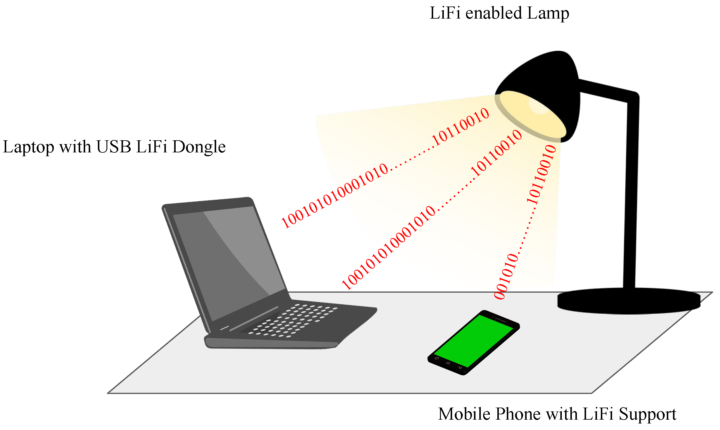 Figure 1.
 VLC enabled Lamp.
2. Generic OCC Architecture
Figure 2, shows a generalized block diagram of an OCC system. The input binary data stream is passed to Optical Signal Modulator which modulates the signal using the selected technique. The modulated signal is mapped to the LED driver which is used to control the LED. The modulated signal is transmitted over a free-space optical medium. Mobile phone cameras receive the directed light as live video. The video undergoes frame sampling and thresholding to demodulate the signal and decode the received data.
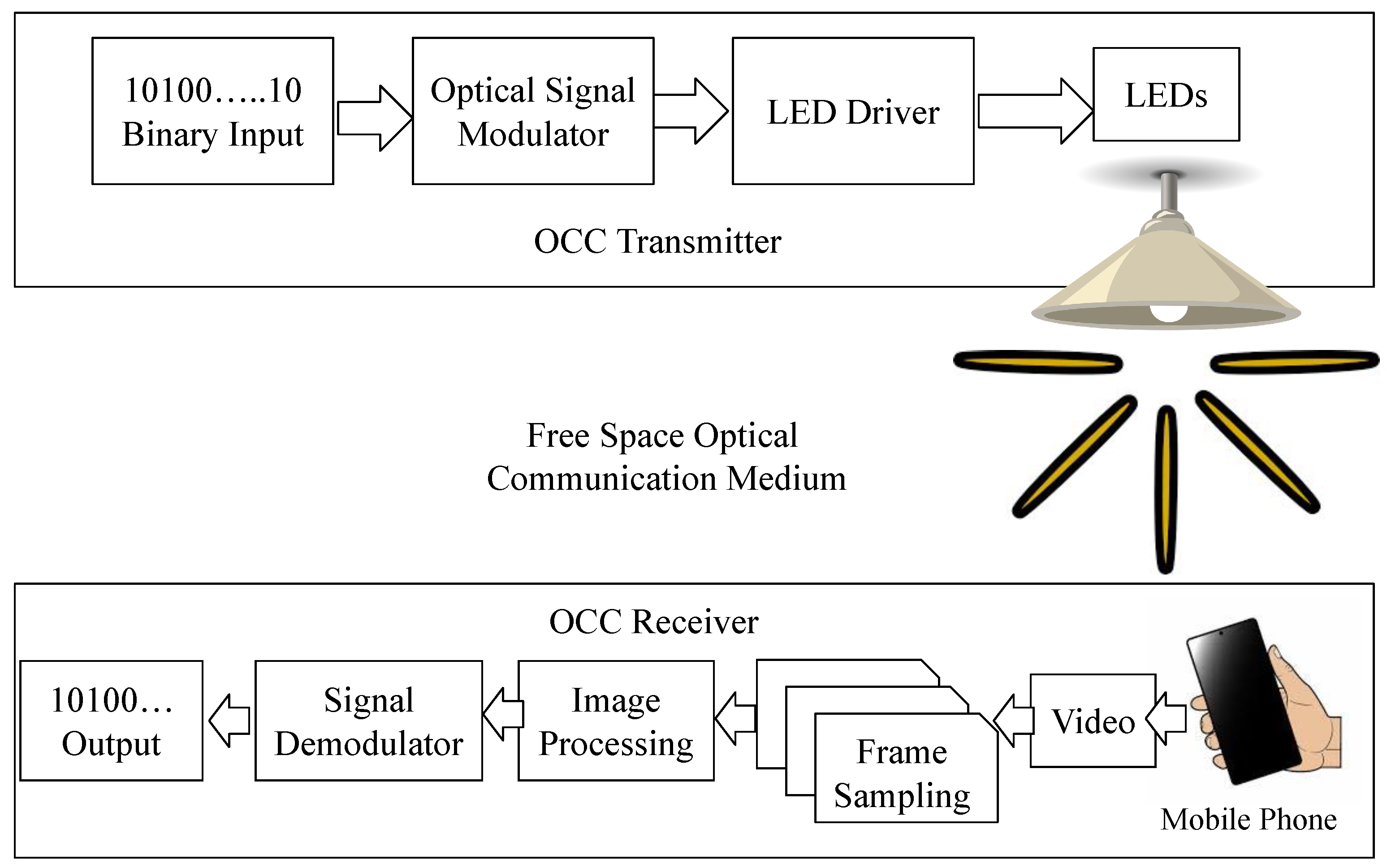 Figure 2.
 The schematic block diagram of an OCC system.
3. Synchronization
The primary deployment of OCC-based Li-Fi systems is typically in a broadcast environment. Thus, there is no feedback channel, unlike RF communication; this limits the dynamic tuning of the receiver equipment to achieve synchronization and thus restricts achieving higher data rates. If the user device starts sampling at any point during transmission, there is a possibility of losing data; this problem is called Random Sampling
[9]. On the other hand, the operational performance of each image sensor varies from product to product; this results in the problem of having different frame rates for different equipment despite the same configurations.
4. Encoding Principle
The basic encoding principle in rolling shutter-based OCC remains the same, i.e., encoding data in stripes. Thus, depending upon the modulation schemes, the properties of stripes will change. For example, in direct OOK modulation, the width of stripes will change based on the bit patterns. Whereas for FSK, the modulated output would vary in the number of stripes, and for CSK, it would be colored bands. Although the number of stripes required to represent a bit determines the efficiency of the modulation technique, it is also dependent on the size of the transmitter
[10].
Figure 3 shows sample frames from each modulation scheme. In FSK, the data is transmitted by modulating the signals in terms of shifting frequencies, while in Pulse Duration Modulation(PDM), it is transmitted by changing the duration of the pulse.
 Figure 3.
 Modulation Patterns.
5. Decoding Principle
An image sensor is built with pixel arrays and a built-in read-out circuit. Each pixel of an image sensor acts as a photodetector. Depending upon the type of camera, these arrays are activated either at once or one by one; this is the basic working principle of the global shutter and rolling shutter. The pixels are activated together in the global shutter, whereas pixels are activated in succession in the rolling shutter. The rolling shutter enables capturing of LED states at different pixels resulting in a series of stripes as shown in Figure 4.
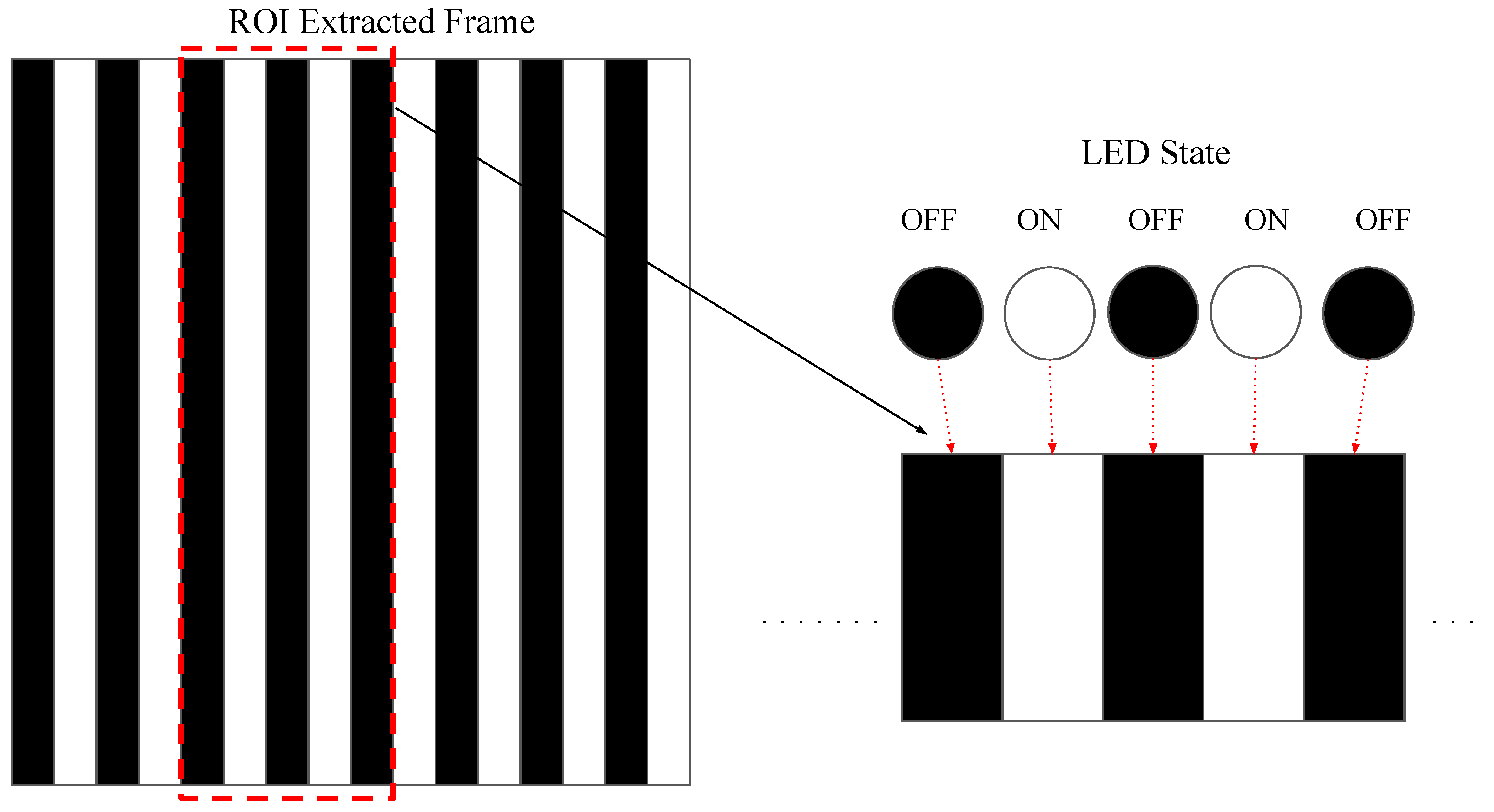 Figure 4.
 Rolling Shutter Effect.
The transmitted bits are decoded using image-processing techniques as shown in Figure 5. The first step is detecting and tracking the transmitter from video frames using computer vision algorithms to identify the Region of Interest (RoI). The RoI from the image is cropped and resized to obtain an image containing stripes. The cropped RoI further undergoes pre-processing to obtain a 2D signal using thresholding and decoding techniques. The decoded binary bits are used to reconstruct sent data.
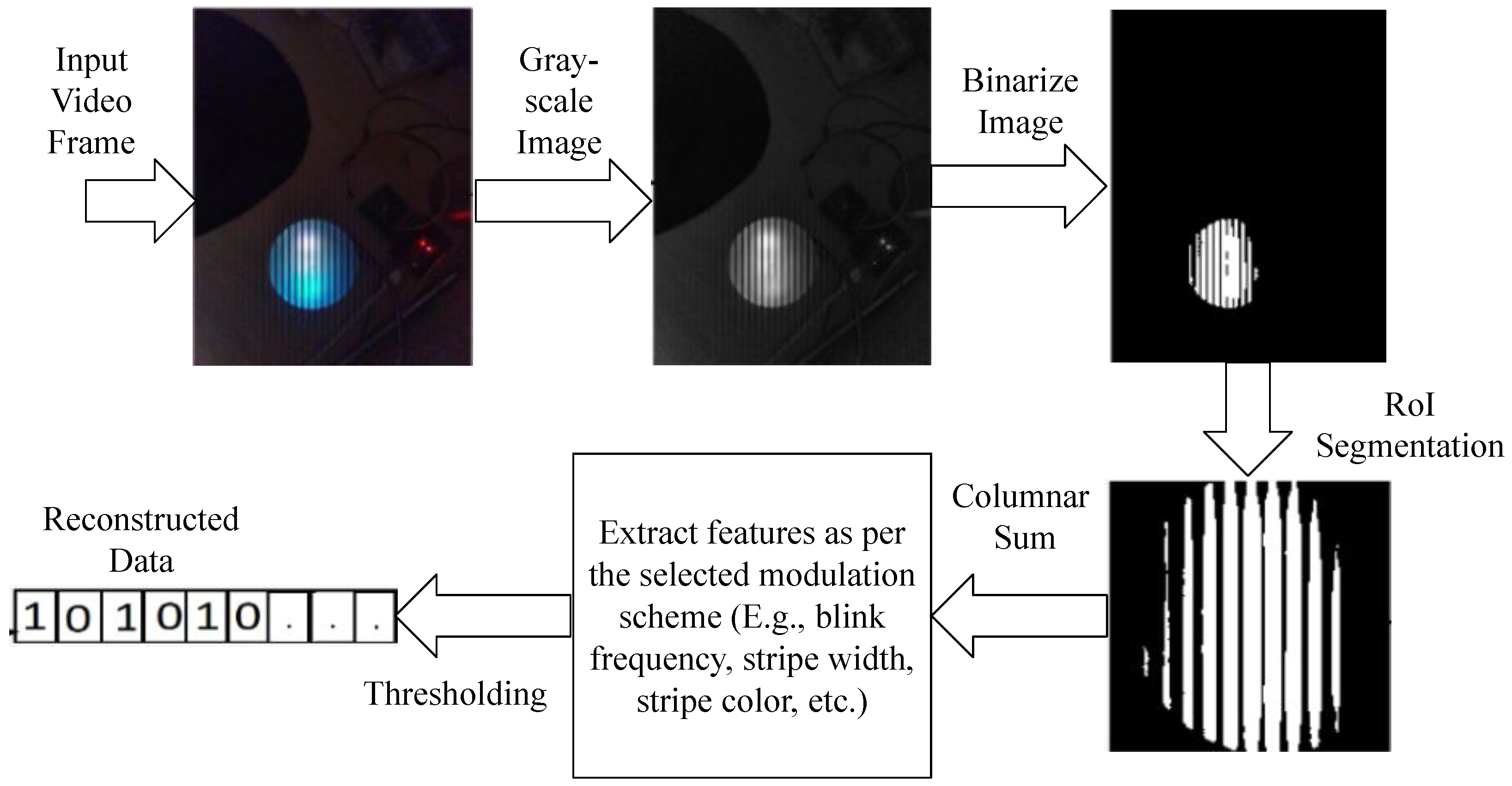 Figure 5.
 Decoding Steps.
6. Performance Evaluation Metrics
In an OCC-based Li-Fi system, the number of frames required to represent a bit is the crucial factor in determining the modulation techniques’ efficiency. In a typical OCC-based Li-Fi system using OOK modulation, the encoded bits are observed as stripes in the image at the receiver side. Thus, the more stripes in the image, the more bits can be encoded. However, the width of these stripes is proportional to the LED transmitter’s symbol rate. Thus, for a higher symbol rate, the corresponding bit rate will be higher, which results in an increase in the number of bits per second. Each bit is represented with the smaller duration of on-off cycles causing the stripe width to become thinner. However, due to the pixel bleeding effect, the image becomes blurred and the width of the stripes becomes difficult to decode. On the other hand, if the stripe width is wider, the number of bits recovered could be less. Hence, there must be a balance between bit representation, modulation technique, image processing, and size of transmitter.
In addition to Signal-to-Noise Ratio(SNR) and Bit Error Ratio (BER), the frames-per-bit
[7] metric will also be used to evaluate the performance of the proposed modulation technique. SNR under various ambient lighting conditions and distances will be recorded. To measure SNR the ratio of overall pixel intensity of the image during transmission and before the transmission will be estimated.
This entry is adapted from the peer-reviewed paper 10.3390/computation10070110