The power supply is usually the bottleneck for marine distributed systems such as buoys. Wave energy technologies are especially useful in this sense, as they can capture and convert the promising “native” renewable energy in the ocean (i.e., wave energy) into electricity.
1. Introduction
A buoy refers to a float on the sea surface, traditionally used to show a navigable channel or to indicate reefs, submerged wrecks, etc. Ever since the 1920s, it has become an important platform, carrying a variety of monitoring devices [
1]. Their in-situ measurement data are getting more and more critical in disaster prevention, resource exploitation, scientific research and national security [
2,
3]. Modern technologies have gradually made the buoy multifunctional, or “smarter” [
4]. Smart buoys can be embedded into a full-coverage marine information-monitoring network consisting of radars, vessels, satellites and land-based monitoring nodes [
5,
6]. With extensive application scenarios, the marine (monitoring) buoys are developing rapidly [
7,
8]. The U.S. National Data Buoy Center owns 1324 buoy stations that collect and transmit ocean observation data [
9]. The World Meteorological Organization and the UN Educational, Scientific and Cultural Organization jointly initialized a data buoy cooperation, namely, the Drifting Buoy Cooperation Panel, which deploys over 400 anchored buoys and 1250 drifting buoys [
10].
The extensive application/deployment of marine buoys requires an essentially economically feasible and physically feasible power solution. In fact, powering the distributed devices off the grid has always been a bottleneck problem [
11]. Due to limited accessibility to power supply, the traditional buoys have to work in certain ways to reduce power consumption. One option is to adopt devices with only a low voltage and low power. Otherwise, the devices need to operate under intermittent working mode, in which, they work and hibernate periodically [
12,
13]. The battery limits the independence of the distributed systems; that is, until the emergence of renewable energy technologies. In current practices, many buoys work with a combination of solar panels and rechargeable batteries [
14]. This reduces the hibernating interval, making most small-scale devices functional all of the time, which is critical for real-time monitoring/data acquisition.
As a very “native” and almost exclusive energy in oceans, wave energy would become the “target fuel” of marine buoys for many reasons [
15]. Wave energy harvesting is a carbon-free process used to achieve power conveniently in oceans (71% of Earth’s surface), making it a very promising renewable energy [
16,
17]. Wave energy comes to marine buoys more naturally due to its “surface” distribution. Wave energy highly concentrates within a small portion of the water depth (i.e., near the surface). The dispersion relationship indicates that the water particle velocity decays to 5% of the maximum particle velocity (at the surface) as the depth increases to half of the wavelength [
18]. The application domain of marine buoys is exactly the “prime zone” of wave energy.
Solar energy and wind energy are the major competitors of wave energy [
19], especially in the aspect of powering marine buoys. Some marine buoys have already adopted solar/wind as their power resources (e.g., WindSentinel buoy [
20]). However, that does not mean that they are the ultimate solutions for marine buoys. Ocean waves transmit in water, a medium that has a much higher density than air, meaning that they could yield a higher energy density than wind. In fact, the power density of a wind farm is typically in the order of 0.4–0.6 kW/m
2, whereas wave energy is typically in the order of several 2–3 kW/m
2 (solar photovoltaics typically generate power in the order of 0.1–0.2 kW/m
2) [
21]. Furthermore, wave energy is more consistent than solar/wind energy. In the U.K., wave energy can be harvested up to 90% of the time, whereas solar/wind can be harvested for only 20–30% of the time [
22].
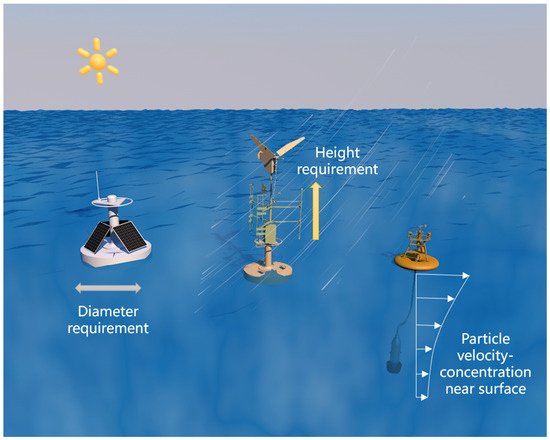
In terms of engineering, the wind turbines’ requirement for clearance height is quite incompatible with marine buoys. The clearance height means that the buoy needs to include an additional structure with a considerable (relative to the height of the buoys) freeboard [
23,
24]. This would significantly increase the capsizing vulnerability, as well as the structural materials, and harm the concealment of marine buoys. Similarly, solar panels’ requirement for surface area forms a challenge for marine buoys [
19]. Considering the relatively lower power density of the solar energy, it would create a contradiction between the buoy’s horizontal dimension and its load capacity. In addition, solar panels need to stay away from run-up waves, making a solar power system less stable in marine environments [
10,
13].
Figure 1 is a concise diagram showing the primary engineering challenges corresponding to various power systems on buoys.
Figure 1. Engineering challenges for various power systems on buoys.
In addition, placing solar panels within the buoys may require bending the panels around the surface (e.g., a spherical shape) to protect them from the marine environment within the hull. This is difficult enough as is, yet can be aggravated by the filter of water overtopping the buoy. Reports mentioned that guano from birds usually accumulate on the surface of buoys in practice, which may greatly impair the efficiency of solar panels over time [
10]. There are also considerable ecological concerns with the offshore wind turbines (e.g., noise, collision, electromagnetic field). For example, floating wind turbines could increase the risk of seabird–turbine collision, as the motions of the turbines make collision risk more dynamic [
25].
The primary motivation for this review study is the importance of wave energy marine buoys from multiple perspectives. Marine buoys have become the most common, small-to-medium-scale (relative to offshore platforms etc.) floating structure that needs to work off the grid. Therefore, they are very representative in that they reflect the development of the distributed system in this scale (roughly 10
−1 m~10 m) [
15,
26]. On the other hand, wave energy utilization on marine buoys primarily aims to provide in situ power supply, which is less demanding than power stations (aiming to supply power to the grid or other systems) [
27,
28].
2. Energy Capture from Wave to Structure
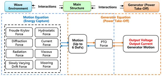
The wave energy utilization can be decomposed into two critical processes: (wave) energy capture and PTO.
Figure 2 depicts the generic working mechanism of a wave energy marine buoy. Energy capture is upstream of wave energy utilization, which refers to the critical process of harvesting the wave (fluid) energy with the main structures (solid) and achieving the mechanical energy for PTO. Therefore, energy capture is governed by the fluid–structure interactions (i.e., hydrodynamics), which are subject to the inputs (e.g., wave height, period, water depth, etc.) and the main structure design (such as floating structure dimension, geometry, mass, moment of inertia, center of gravity, mooring configuration and stiffness, etc.). Though they have not converged, mainstream designs of energy capture include three categories: oscillating water columns (OWC), oscillating bodies (OB) and overtopping devices [
31].
Figure 2. A mechanism diagram of a wave energy marine buoy.
Overtopping devices are structures that “trap” the water from the run-up waves [
32]. The trapped water provides a water head higher than the mean sea surface that turns into water flow out through a duct, which drives an axial flow turbine and, in turn, the generator in order to produce electricity [
33]. Wave Dragon is the world’s first grid-connected floating overtopping device [
34]. Overtopping devices are advantageous in that they largely stabilize the unstable input waves to the PTO and they usually work with low-head hydro turbines (standard for hydroelectric stations) [
33,
35]. Overtopping devices usually involve larger dimensions (e.g., Wave Dragon [
34]) or fixed infrastructures (e.g., OBREC [
35]), as they work in a similar way to a reservoir/hydroelectric station. Therefore, an overtopping device is not considered for marine buoys and the following discussions concern the other two types: OWC and OB.
3. PTO from Structure to Wire
The PTO is the other critical process that essentially “converts” the mechanical energy into electrical energy, which is governed by structure–generator interactions (i.e., electrodynamics). The performance of the system is highly dependent on the interactions between the wave environment, main structure and the generators. Wave-to-wire modelling (W2W) is being developed to address these interactions with high fidelity [
66,
67]. The PTO determines not only the output power, but also the dimension, cost and operational life of the system. Based on the generator mechanism, this research classifies wave energy PTOs for marine buoys according to the generator type: electromagnetic generator (EMG) and triboelectric nanogenerator (TENG).
4. Applications of Wave Energy Marine Buoy
The functional loads onboarding the marine buoys include navigation beacons, sensors, data acquisitors and communication devices, etc. With the expansion of buoy functions, the number of electronic equipment carried is gradually increasing, and the power consumption of the buoy is also increasing. In order to ensure the normal operation of marine buoys, solar battery systems need to mix other energy sources, such as wave energy, microbial fuel and wind energy, in order to prolong the service span of the buoy system and improve the charge/discharge efficiency [
106]. According to the specific application requirements, a variety of buoy systems have been developed. The representative ones include power supply buoys, data buoys, navigational buoys, drifter buoys and aquaculture buoys [
107]. Some of them are listed in
Table 1.
Table 1. Typical applications of marine buoys.
With the progress of wave energy technologies, some attempts have evolved into large, non-cylindrical platforms, while many still fall into the buoy scale. Large buoys can output the electricity to the grid or to other marine structures instead of serving themselves only. Wavebob is a two-body heaving buoys system developed for the sheltered waters of Ireland. The rated power of Wavebob reaches 1000 kW and is considered highly adaptive to Mediterranean environments [
109]. Ocean Power Technologies developed the first commercial WEC in the U.S., PowerBuoy, which acts as an uninterruptable power supply (UPS) that constantly recharges itself by harvesting wave energy. Deployed to supply devices on-board or underwater, the PowerBuoy3 incorporates a redesigned PTO, a battery pack, a higher voltage power management and distribution system and a novel auto-ballasting system [
110]. Other power supply buoys include the OEbuoy [
111], AquaBuOY [
120] and AWS [
121]. Generally speaking, power supply buoys yield quite good performances, yet their survivability and financial feasibility are subject to examination and improvements [
109]. This is why the power supply buoys are more inclined to step into the segment market (e.g., PowerBuoy in the offshore applications) instead of the general power grid, for now.
In terms of offshore applications, wave energy buoys are very promising. In fact, the earliest successful application of wave energy technologies is realized on a navigation buoy (probably the most straightforward mission for marine buoys). Masuda’s navigation buoy captures wave energy with an OWC and converts it to electricity through a turbine-drive rotational generator. The buoys were commercialized in large numbers in Japan and the U.S. as navigation equipment, and proved to be the first successful wave-powered devices in real applications [
44]. The first commercially manufactured wave energy device in China also turned out to be the navigation buoy developed by Guangzhou Energy Research Institute. Since the late 1980s, around 800 wave energy navigational buoy products have been purchased by clients in China, Singapore and the U.K [
122]. The Chinese wave energy navigation buoys also adopt the combination of an OWC and turbine-drive rotational generator, while the PTOs are becoming more powerful and more mature. On top of this, the buoy-based PTOs developed by the Chinese Academy of Science have evolved into multiple models (10 W, 100 W and kW). In 2020, a comprehensive wave energy data buoy, “Hailing”, operated without any failure for one year in South China Sea. “Hailing” implemented two 60 W wave energy pneumatic generators, one 30 W solar panel and a complementary power management system [
123]. This means that wave energy could become the major renewable energy source for the mid-scale buoy.
As nerve nodes to the ocean, marine sensors perceive all sorts of valuable physical quantities, such as conductivity (salinity), temperature, depth (pressure), wave, wind, current (tide), radiation, turbidity, potential of hydrogen, dissolved oxygen and nitrogen concentration [
124]. In many occasions, the signals from the sensors need to be delivered to data acquisitors, in which, they are turned into time series in certain steps to be stored, transmitted or processed [
125,
126,
127]. The data are used to predict the weather [
128], hurricanes and cyclones [
129] and monitor the environment [
130]. The earlier representative of the data buoy is the McLane moored profiler designed by Woods Hole Institute (with an auto-lifting function) [
131] and that designed by Norway SAIV AS with an electrical winch [
132]. The international Argo project has deployed over 3200 oceanographic data buoys to increase sampling quantities and coverage in time and area [
133]. Other data buoys could be the buoys carrying GNSS receivers for geological monitoring [
134] and the drifting buoys with INSAT communication for the sea surface observations [
115].
Compared to power supply buoys or navigation buoys, data/sensor buoys do not require much volume. In fact, data/sensor buoys can be relatively small-scale. The Seahorse buoy is an autonomous profiler designed by Bedford Institute of Canada that consists of a buoy, jacketed wire, suspended weight and buoyant instrument package. The Seahorse buoy utilizes wave energy to deliver the buoyant instrument downward along the mooring line [
135]. The successor of Seahorse, Wirewalker, follows a similar wave-powered mechanism, but makes the device even simpler and cheaper [
136]. The U.S. Navy’s sonobuoy AN/SSQ-101 is an air-deployable active receiver. It is said that AN/SSQ-101 is powered by converting wave energy through an integrated linear magnetic generator [
137]. Wave energy greatly increased the mission endurance. In turn, the unit cost of AN/SSQ-101 is significantly reduced so that it can be extended to civilian purposes, such as monitoring marine mammals, port security and seismic activity [
138].
Due to the limitations with the battery of the buoy, the service availability of the functional device on-boarding a buoy is largely determined by its standby time and its temporal resolution [
139]. The power requirement of the functional devices involved with buoys ranges from 10
−3 W to 10
2 W. Approximately a quarter of them (mostly small-scale, single-function sensors) have a power consumption of less than 1 W. Over half of them have a power consumption within 1–10 W (e.g., camera). Approximately 20% of the functional devices require a power of 10–100 W (e.g., beacon light), whereas the rest (requiring more than 100 W) are some larger-scale, comprehensive systems [
140].
The wave energy technologies could be extended to other marine buoys. In fact, as the world population and economy grow, the demand for marine protein has increased rapidly in the past few decades. Aquaculture buoys are effective equipment used to increase aquaculture production and, at the same time, protect the environment. Echo-sounder buoys could reduce the number and impact of fish-aggregating devices [
117]. Low-cost aquaculture buoys could collect physical, chemical and biological data from marine farms, which help to determine whether the area is suitable for activities such as lobster breeding [
13]. The finfish-breeding buoy could store different types of feed for a long time [
116], whereas the feed buoy could feed fish autonomously [
141]. Generally speaking, small-scale buoys such as aquaculture buoys follow a design philosophy of being low-cost and robust. Therefore, sensor buoys and aquaculture buoys have become an appropriate application scenario for the TENG-based PTO. A combination of single-body OB and flexible track nanogenerator could power these buoys in a robust way [
142,
143].
Dynamic environments are usually the negative factors for solar panels, but, to a certain extent, they can supply more energy to wave power systems [
144]. Many studies on self-powered buoys are attempting to shift the buoys’ power source from solar energy to wave energy in order to reduce weight and to increase the power capacity [
145]. For instance, a position-tracking buoy powered by a wave-drive EMG-TENG hybrid generator has been developed by Chandrasekhar et al. Sea trials revealed that the wave-powered buoy realized GPS position tracking for itself a few kilometers away from shore [
146]. Li et al. developed an EMG-based wave energy powered buoy that could automatically charge a lithium battery and discharge external loads. In sea trials in the Yellow Sea, it yielded a power density of 210 W/m
3, which is adequate for supporting many low-power sensors [
84]. A modular wave-energy-powered buoy (developed by Vella et al.) went through a series of model tests under both regular and random waves. The buoy generated an average power output value of around 0.9 W under a mild sea state of a 0.2 m wave height, meaning that it could become an observational buoy with a longer lifespan [
147]. Chen et al. developed a wave-energy-powered buoy by integrating an EMG/TENG hybrid generator. The buoy served as a self-powered sensing node and transmitted the sensing data over a distance of 300 m in real sea trials [
148].
It is found that the above wave energy marine buoys can be categorized into “wave energy converter buoys” (such as Ocean Power Technologies’ PB3, AWS’ Archimedes Wave) and “wave energy powered buoys” (such as Masuda’s navigation buoy, AN/SSQ-101 sonobuoy) depending on whether they can output electrical power to exterior payloads not on-boarding the buoy. There is not a solid boundary for the two buoy types. In fact, PB3 can be scaled down (at a reduced cost) to supply power only to on-board payloads [
56]. AWS’ Archimedes Wave can be scaled up to over 500 kW per unit, making it closer to a power station [
121].
This entry is adapted from the peer-reviewed paper 10.3390/jmse10050566