Your browser does not fully support modern features. Please upgrade for a smoother experience.
Please note this is an old version of this entry, which may differ significantly from the current revision.
As the battery provides the entire propulsion power in electric vehicles (EVs), the utmost importance should be ascribed to the battery management system (BMS) which controls all the activities associated with the battery.
- battery management system
- state estimation
- cell-balancing
1. Internal Architecture of the Battery Management System in Electric Vehicles
The BMS is usually an embedded system and a purpose-built electronic regulator that performs the functions of monitoring, along with controlling certain quantities, such as current, voltage, and the temperature of batteries, thus maintaining battery cells within a safe operating region [29]. A general framework of a BMS used in electric vehicles is shown in Figure 1. From the architectural representation, the data flow in BMS can be represented in the form of input, data processing and output signals.
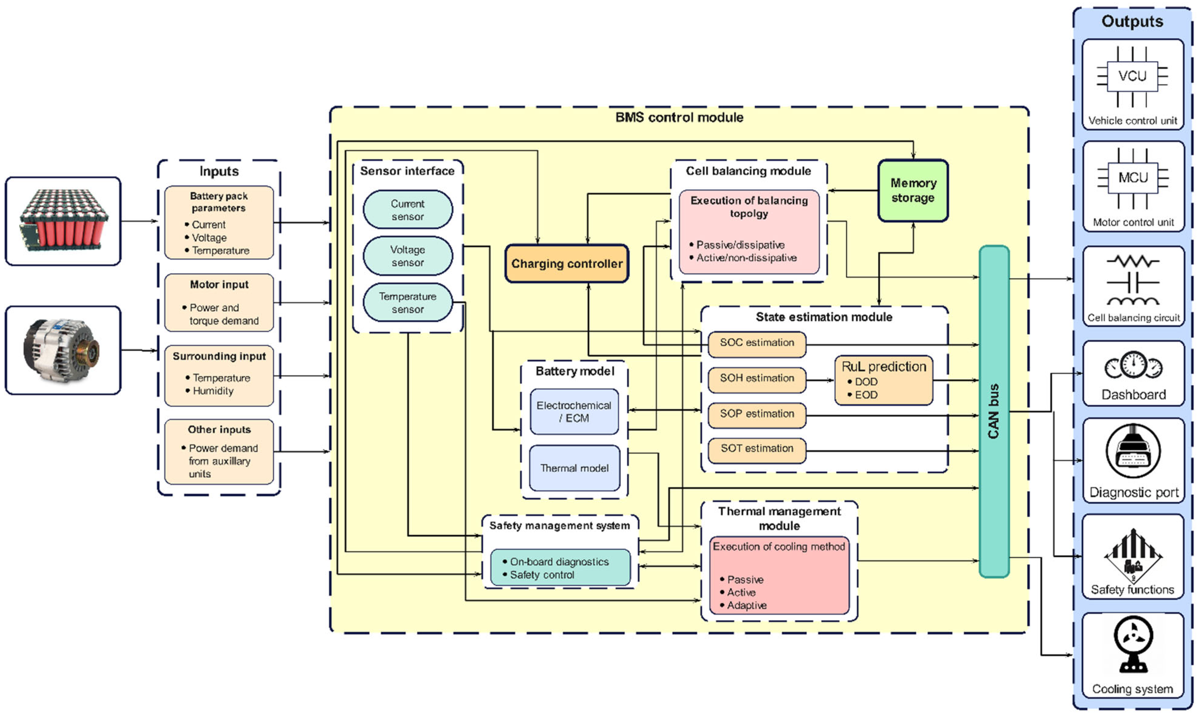
Figure 1. Internal architecture of BMS in an electric vehicle.
1.1. Inputs to BMS
The most essential input quantities are the battery pack current, voltage, and temperature. These inputs serve as the basis for monitoring the battery behavior and maintaining its operation within safe limits. Moreover, the power demand of the motor based on the input received from the throttle system, and the power demands of auxiliary units present in the EV, serve as other inputs to the BMS. The BMS supplies energy to drive the EV according to the motor’s power and torque requirement.
1.2. Control Module in BMS
The entire BMS is formed by combining multiple modules and establishing a communication route among these modules. The major modules necessary to realize the BMS are battery modeling, state estimation, cell-balancing, and thermal management. The communication between them is established using a controller area network (CAN) bus. The on-board current sensor and voltage sensor detect the current and voltage of the battery directly, and the surface temperature of the battery pack or cells is detected by temperature sensors. The BMS contains various battery models including an electrochemical model (ECM) and a thermal model. Battery models are essential for accurate prediction and optimization of different parameters, such as current, voltage, and temperature values obtained from the measured sensors which are crucial for estimating relevant battery states, such as SOC, SOH, SOP, and the remaining useful life (RUL) [30,31]. The SOC and corrected input voltage from the battery model are utilized by the cell-balancing module which aims to attain a uniform voltage distribution among the battery cells. The BTMS then acquires temperature-related input from the battery pack, battery models, SOT and surroundings, based on which it executes an appropriate cooling strategy to keep the temperature of the battery pack within safe limits [32]. A safety management module (SMM) and charging controller are also essential to ensure the safe operation of battery. The function of the charging controller is to receive inputs from different modules and to charge/discharge the battery at an optimized rate. For instance, depending on the SOC level of the battery, the controller will regulate the charge/discharge rate. The SMM includes on-board diagnostics and safety controls for the entire battery pack. Its function is to detect the failure of any module inside the BMS and to execute a suitable safety mechanism to preclude harsh consequences from occurring. It constantly communicates with other modules to diagnose faults related to battery overheating, overcharging, over-discharge, thermal runaway, communication errors, abrupt temperature rise, insulation faults, etc., and executes required safety mechanisms to bring the operating voltage and temperature back within safe operating limits [16].
1.3. Outputs from BMS
Control outputs sent by different modules inside the BMS are used to achieve several functions for managing the battery pack. To achieve a uniform SOC/voltage level between cells, a controller in the cell-balancing module operates balancing circuitry according to the magnitude of the voltage/SOC difference. The BTMS will execute an appropriate cooling or heating strategy to maintain the temperature of the battery pack within safe limits. The SMM first performs on-board diagnostics for detecting faults inside the battery pack. Faults detected are communicated to the user through a diagnostic port in the form of diagnostic trouble codes (DTC). Similarly, the major issues associated with battery temperature and voltage are sent to a dashboard to make the user aware of the situation. Then, the SMM activates several cell-level and pack-level controls to mitigate the fault and bring the battery temperature and voltage back within safe working limits. Meanwhile, the BMS maintains constant communication with other control units, such as the motor control unit (MCU) and vehicle control unit (VCU), to meet the power demand of the motor and other auxiliary electronic subsystems. The acquired input data is first utilized by the battery models in predicting the parameters, based on several models, which are later utilized by different internal modules for respective control actions.
2. Battery Modeling in Electric Vehicles
For a safer and more efficient battery operation, accurate prediction of the battery behavior is required. The acquired input quantities, such as current, voltage, and temperature, contain noise in real-time scenarios because of varying operating conditions. Hence, when the directly measured values are used for state estimation, inaccurate results are produced. Therefore, accurate prediction of current, voltage, and temperature is required [33]. This role is fulfilled by the battery model which acts as a major source of data to the state estimations and other modules. These models are embedded with mathematical equations which calculate certain information based on the inputs received from the different battery sensors. Over the years, different battery models have been researched and classified into equivalent circuit models (ECM), electrochemical models and thermal models which are discussed in subsequent sections. However, there is a major difference between them from the point of their model development methodologies which play a detrimental role in the battery management application. The electrochemical models use physical laws that govern the internal electrochemical processes of the battery, whereas ECMs use a combination of resistors, capacitors, voltage sources, etc., to mimic the battery behavior [34]. Whatever the approach, the battery model must prove itself in terms of its accuracy, configuration effort required, computational complexity and interpretation ability. Figure 2 depicts the architecture schematic of battery models in the BMS.
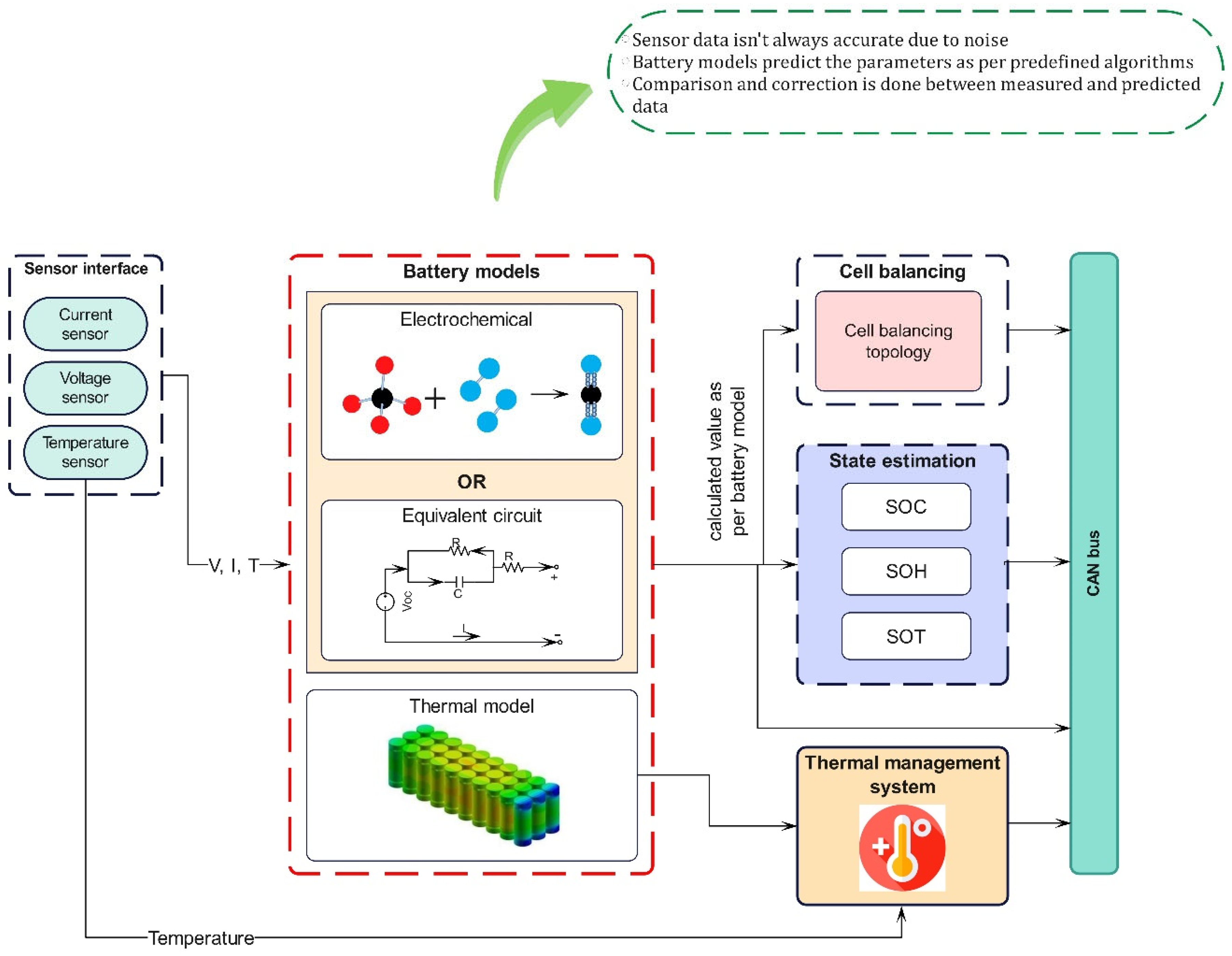
Figure 2. Internal architecture of battery model in BMS.
2.1. Control Module in BMS
In this model, the electrochemical processes that occur in the batteries are represented by utilizing a set of coupled non-linear partial differential equations (PDE). They provide full information on the internal electrochemical dynamics, thermodynamic and kinetic phenomena occurring in the cell [35]. The typical representatives of the electrochemical model are the Shepherd, Nernst, Unnewehr universal and combined models. The Shepherd model describes the battery electrochemical behavior in terms of voltage and current, whereas the Unnewehr universal model is a simplification of the Shepherd model. It attempts to model the variation in the resistance to the SOC, whilst the Nernst model uses the exponential function to determine the SOC. The estimation of voltage using the Shepherd model follows experimental data closely and was found to be more precise than the Nernst model. This was verified since a higher estimated voltage error was observed when using the Nernst model. The combination models were found to be more accurate as they inherited the best features of all three models; however, the associated complexity often leads to an increased memory requirement and computational effort due to a large number of unknown parameters and may lead to reduced on-site accuracy when applied in the vehicle systems [36]. This can be countered by reducing the order of the model by discretization techniques to retain only the most significant dynamics of the full-order model. To overcome these complications, researchers have attempted to develop ECMs which use non-linear elements instead of PDEs.
2.2. Equivalent Circuit Model (ECM)
The electrochemical model possesses a greater degree of complexity, which is further aggravated by parameter identification as analytical solutions do not exist for them [37]. Hence, ECMs are being adopted in more pragmatic situations, specifically in electric vehicles. They include the Rint model [38], Thevenin model [39], DP model [40] and the PNGV model [41]. ECMs use a combination of electric elements, such as inductors, capacitors, resistors, and, in some cases, Warburg impedance. The Rint model, the simplest form of ECM, contains internal ohmic resistance and an OCV source, the value of which depends on the SOC, SOH and the temperature of the lithium-ion batteries. Comparatively, it has the highest estimation errors as it does not account for the dynamic voltage performance. The Thevenin model is an extension of the Rint model having a parallel RC network in series to simulate the polarization effects. The DP model (also known as the second-order RC circuit), represents an improvement over the existing Thevenin model, and uses two parallel RC networks to describe the nonlinear polarization response of the LIB. The Thevenin and DP models have good estimation precision with small voltage errors [35]. The recently developed PNGV model has an added capacitor in series based on the Thevenin model [42]. Though the PNGV has higher accuracy in simulating the transient response process, as well as accounting for more complexities, The PNGV has higher accuracy in simulating the transient response process, as well as accounting for more complexities. Theoretically, the model should be analogous to the behavior of the battery in actual life but the existing equipment cannot detect the polarization process in detail making the capacitance determination impossible [43]. Therefore, the dual RC circuit or the DP model offers the best real-time performance and gives a more accurate SOC estimation compared to the other models [42]. As a result, the ECMs are preferred for battery modeling in EVs. On the basis of an equivalent circuit with elements and interconnections in lithium-ion batteries, the proposed design’s equivalent circuit is presented in Figure 3. Both the cathode and anode electrochemical reactions are represented by a series connection of interfacial capacitance and associated charge transfer resistance with Warburg impedance. An external inductive element, consisting of an inductor and resistor (L1 and R1) connected to the wiring between the electrodes and the measuring instruments, including the wounded current collector, is also included in the circuit. The cathode is shown as a model consisting of two distinct radiuses of active materials. The capacitance between the electrolyte and the electrical connection between particles must be placed in parallel with different pairs of series connections of diffusion elements and charge transfer resistance [44]. The only parameter left to be considered for modeling is the temperature distribution in the battery. The thermal models predict the heat generation and dissipation behavior within the battery according to which the thermal management system can function to achieve cooling.
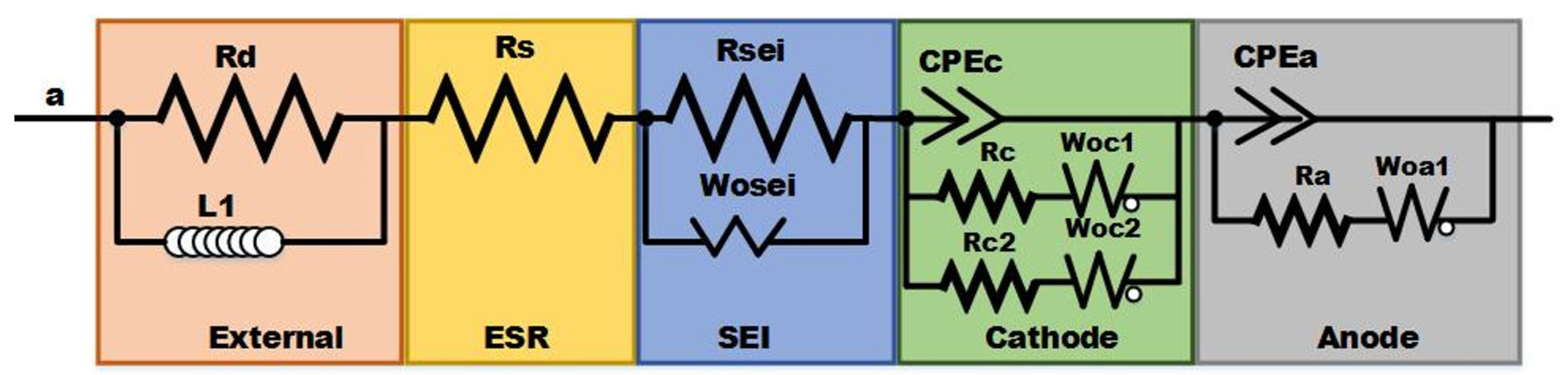
Figure 3. Electrochemical Impedance Spectroscopy Analysis Equivalent Circuit.
2.3. Battery Thermal Modeling
It is essential to completely understand the heat generation characteristics and their dissipation in a Li-ion battery from a safety as well as an efficiency point of view. Controlling the temperature under the limiting values in all driving conditions is necessary. Hence, a thermal model is necessary which calculates and predicts the heat generation and dissipation rate of the battery pack. Among the various thermal models, a finite volume-based method is employed for transient thermal analysis and achieving real-time battery-pack cooling control [45]. The model effectively predicts the thermal behavior of the battery under various cooling conditions and duty cycles with a minimum temperature difference of nearly 3 °C between the actual and predicted values. Further, numerical modeling has proven to be valuable in studying the thermal behavior of the battery pack. Theoretically, calculating the heat generation and dissipation based on various heat transfer equations also gives lesser errors compared to the finite volume technique. It is also feasible considering the requirement of time and cost consumption with an accuracy of prediction within 1 °C [46]. In addition, a coupled electrochemical model is implied which evaluates the effect of the current and coolant flow rate on the battery temperature. The three-dimensional CFD-based electrochemical models are effective in reducing the requirements of different sensors and providing higher prediction accuracy [47]. A matter of concern in these numerical methods is that obtaining the values can be a tedious task for which a novel modeling method, called the Foster network model, has been devised. This method has also proven beneficial since the results obtained are comparable to CFD simulation, but they are obtained within minutes, unlike the time-consuming CFD calculations [48]. Apart from the conventional heat source, the study of thermal models enables learning about the ohmic and reversible heat generation occurring due to the internal chemical reaction in the battery. The battery modeling is an inevitable component of a BMS and, hence, constant efforts are put in to develop models with the latest technical approaches by harnessing the power of the large data generated.
3. Battery State Estimation Methods
In BMS, battery state estimation is crucial by which the critical internal states are identified and monitored. Credible knowledge of the state of health (SOH), state of charge (SOC) and state of power (SOP) are necessary prerequisites for effective charging, and the thermal and health management of the battery. The schematic of the architecture presented in Figure 4 highlights the battery dynamics related to various state estimation parameters. This kind of model-based approach is widely adopted in EV applications.
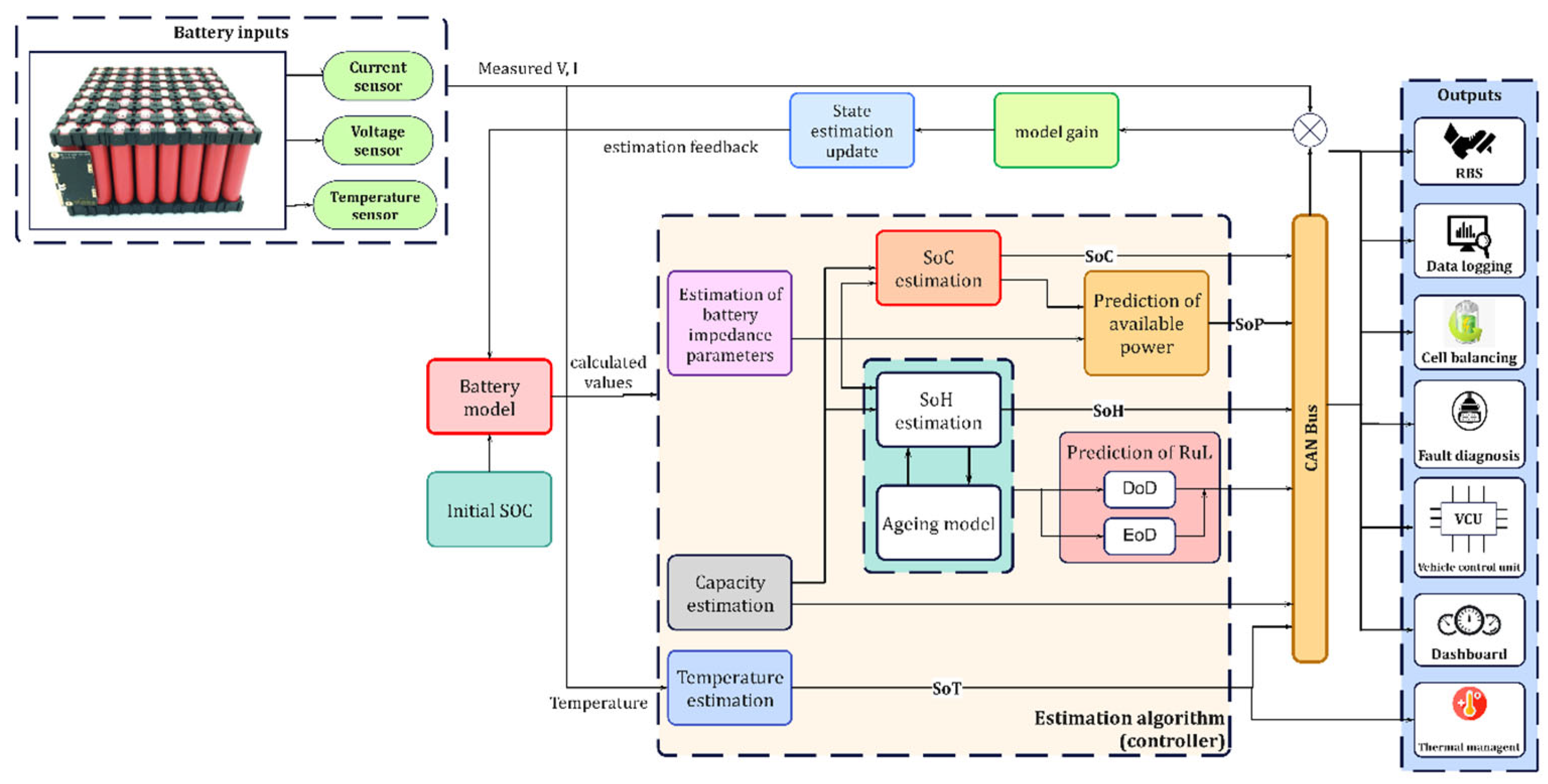
Figure 4. Internal architecture of a battery state estimation module.
In this approach, the accurate voltage, temperature and current values, predicted by battery models using advanced algorithms, are used as input. The main idea behind this method is to link the measured voltage, current and other variables with the battery states via predetermined complex mathematical equations [43]. By taking these parameters as the input to the model, a predicted value is obtained. The error between the predicted and the actual sampled value is calculated and further adjusted so that the estimated value of the state quantity follows the true value. Finally, the state values of SOC, SOH and SOP are obtained through various filters or observers. Then the respective estimated states are given as output to different systems and driver interfaces for communication. The different state estimation techniques are summarized and presented in the following sections.
3.1. State of Charge Estimation Approaches
Among different states, the battery SOC indicates the available battery capacity and, hence, accurate estimation of the SOC is necessary for energy management in EVs [27]. The SOC of a cell is defined as the ratio of the current capacity of the cell to its nominal capacity. The nominal capacity is the maximum capacity of the battery given by the manufacturer. The equation for the estimation of SOC is given in Equation (1).
where QC is the current capacity and QN is the nominal capacity. The numerous techniques employed in SOC estimation can be categorized as either direct, model-based or data-driven. The prominent techniques adopted by researchers for SOC estimation are presented in Figure 5 and their outcomes and results are covered in Table 1. The direct methods, such as open-circuit voltage, internal resistance, Coulomb counting, etc., are accurate, but they are not suitable for adaptation in real-time due to the requirement of longer rest times before measuring or sensor errors inclusion. Hence, these methods are not being implied in EVs [49]. Instead, certain filter-based methods, such as the Kalman filter (KF), particle filter (PF), and H∞ filter, placed under the model-based category, are used in SOC estimation. These methods are capable of restricting the effects of uncertainty and perturbation leading to minimal errors as low as 2% in the estimated SOC [50]. The KF algorithm has a significant value in EVs as it overcomes the shortcoming of current integration dependence on the initial value and does not even require large sample data [51]. The model-based category also encompasses some non-linear, observer-based methods that provide a fast convergence rate and high estimation accuracy [27,52]. However, the Kalman and particle-based filter methods show less errors in estimation, e.g., the filter-based methods give a maximum error in the range of 0.1–2%, whereas the observer-based methods range around 2–3% [52]. Finally, the data-driven methods presume the Li-ion battery as a black-box model and learn the internal dynamics using different measured data. Well-known examples include fuzzy logic, neural network and genetic algorithm, which also present more errors in estimation (ranging between 3–6%) when compared with filter-based methods [52]. However, in data-driven-based deep learning, pre-training the model can be performed with a massive amount of data to improve the calculation speed and prediction accuracy [53]. This has proved to be a promising method if the data handling and storage issues are tackled properly. All the SOC estimation methods play a significant role, since they influence the battery SOH in the long term, which is further discussed below.
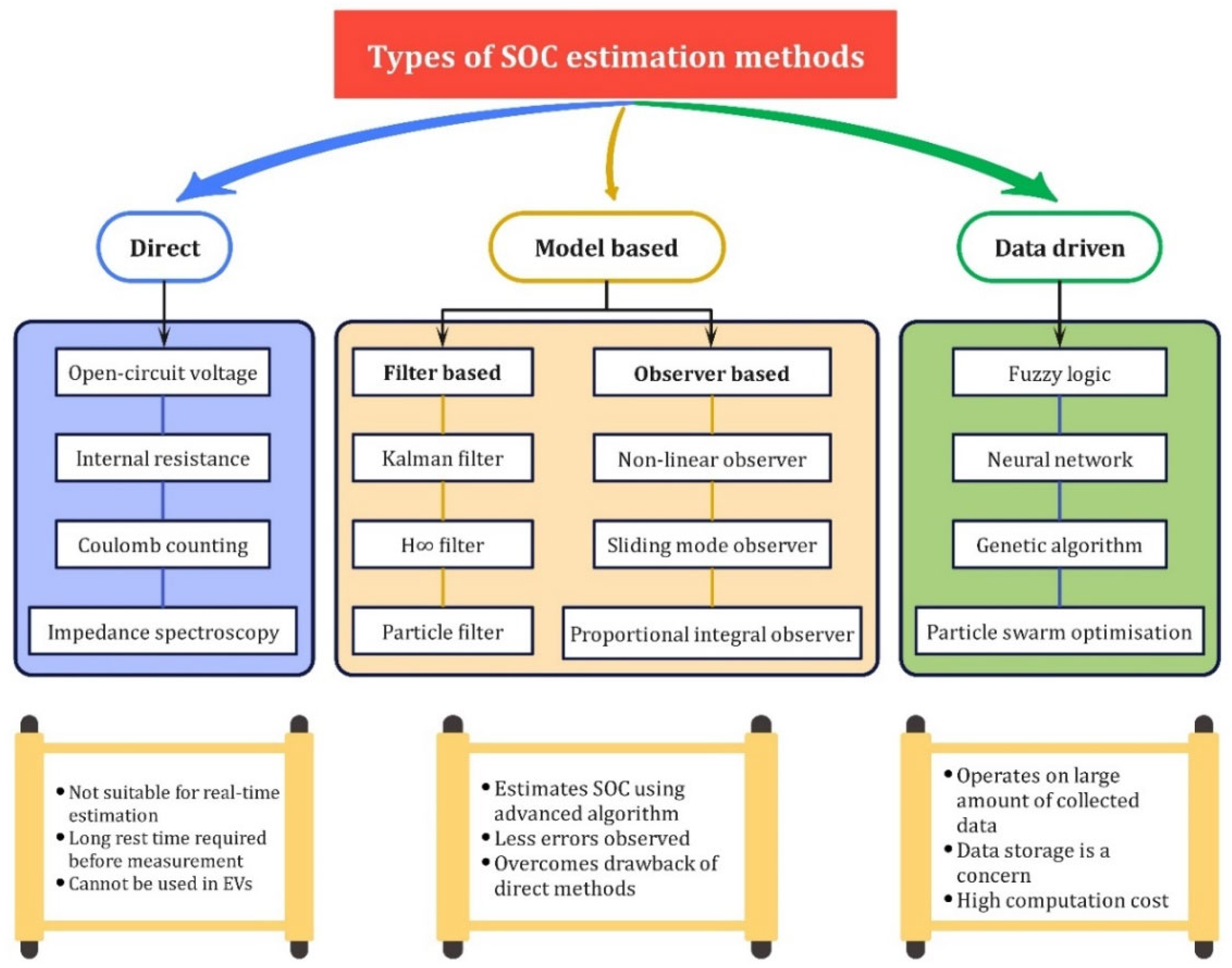
Figure 5. Schematic of different SOC estimation methods.
Table 1. Summary of SOC estimation control techniques.
| Control Approach | Category | Significant Outcomes | Reference | Maximum Error |
|---|---|---|---|---|
| Reduced order EKF | Model-based | Decreases calculation time and improves accuracy | [54] | <2% |
| Robust EKF | More accurate than standard EKF since its prediction errors are less | [55] | ≈1% | |
| Backstepping PDE observer | The resulting gains do not require additional states since it has a closed-form solution adding to computational benefit | [56] | - | |
| Adaptive cubature Kalman filter (ACKF) | Better accuracy and stability than CKF and EKF hence suitable for real application | [57] | 1.85% | |
| IPSO-EKF algorithm | It can better track OCV and maintain good stability in parameter identification | [58] | 0.51% | |
| Unscented Kalman filter | Compared to other estimation methods, it can estimate battery SOC in real-time and has strong anti-interference performance | [59] | - | |
| Adaptive unscented Kalman filter | Error observed in SOC estimation was lower than in standard unscented Kalman filter | [51] | 0.7% | |
| Deep learning- based algorithm | Data-driven | Accurate SOC estimation is predicted when applied to the real driving cycle | [53] | RMSE ≈ 0.5 |
| Time-delay neural network | Better adaptability and robustness against uncertainties and reduced errors are observed | [60] | <5% | |
| Artificial neural network | Effective in estimating real driving cycles with lower errors | [61] | ≈3% |
3.2. State of Health Estimation Approaches
To ensure safety and avoid potential battery failures, proper evaluation of SOH is of paramount importance. SOH is defined as the ratio of discharge capacity to the rated capacity of the battery. SOH estimation is given in Equation (2).
where QNOW is the discharge capacity and QNEW is the rated capacity of the battery. Observing the different studies conducted, the SOH estimation methods can be classified as experimental and model-based methods which are mentioned in Figure 6. Methods such as internal impedance, resistance and capacity level measurements are mainly laboratory-based methods and are not suitable for real-time operating conditions [62]. However, certain model-based methods, including Kalman and related filters [63], and even observer-based methods, are some of the approaches used in EVs. The adaptive observer model estimates the series resistance value which is used to evaluate the SOH of batteries with a fast convergent rate to ensure less error [64]. But this method is based on certain assumptions, such as full cycling with a constant current which cannot be applied in real-time EV batteries. Hence, a more practical application method using neural networks eliminates the dependence on such assumptions and can be used in dynamic scenarios [65]. A similar approach based on a multilayer perception (MLP) scheme is presented which gives errors <1% when a trained model is implemented and the ANN utilizes the actual driving pattern rather than standardized experimental data. Since SOC and SOH are closely related in ways that the charge distribution affects the battery health, the estimation methods are also quite similar. The intelligent data-driven methods that includes optimization algorithms, machine learning methods [20] and self-learning neural networks help in estimating SOH with high precision [66]. For efficient prognostic and health management of the battery, the depth of discharge (DOD) and end of discharge (EOD) time are crucial quantities alongside other states. A battery’s depth of discharge (DoD) indicates the percentage of the battery that has been discharged relative to the overall capacity of the battery. Hence the DoD plays a critical role in determining the battery cycles and ageing in the longer run. Similarly, the EOD time of the battery is the time at which the battery voltage or SOC reach some threshold values, after which the battery needs to be recharged. Hence, accurate prediction of EOD time is also essential in enhancing battery life. Methods such as model predictive, particle filter (PF)-based estimation methods, and recursive least square, are used in DoD estimation. Similarly, the EOD time can be predicted using several ageing models and algorithms, such as the linear regression model [67], particle filtering (PF) with radial basis function neural network (RBF-PF) [68], Bayesian hierarchical model (BHM) [69], electrochemistry-based ageing model [70], PF with outer feedback correction loops (PF-OFCLs) and unscented Kalman filter with outer feedback correction loops (UKF-OFCLs) [71]. The review of SOH estimation methods is tabulated in Table 2. With the battery health kept in check, it is necessary to estimate the future power availability which is taken care of by the SOP estimation.
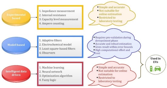
Figure 6. Schematic of different SOH estimation methods.
Table 2. Summary of SOH estimation control techniques.
| Control Approach | Significant Outcomes | Reference | Maximum Error |
|---|---|---|---|
| Single-particle based degradation model | It was able to predict battery capacity fade over a broad temperature range | [72] | RMSE 0.01 |
| Multilayer perceptron | Good performance of SOH estimation in trained and untrained life span | [73] | 0.95% |
| Neural network | The proposed data-driven framework is validated for varying temperatures and extensive driving profiles to estimate SOH | [65] | <2.18% |
| Incremental capacity analysis | A lower fade estimation error was observed in SOH determination | [74] | <3% |
| Support vector machine (SVM) model | Shows fast estimation times and can handle large amounts of battery data | [75] | - |
| Integrated SOH balancing method | It can be applied to second-life battery usage | [76] | - |
| Adaptive observer-based model | The estimated value approaches the actual value very quickly with a small bounded error | [64] | 1% |
| Interacting multiple model (IMM) | The battery states of the system can be uniquely extracted from the measurements | [77] | - |
| Generalized regression neural network | It has shown significant performance improvement due to its approximation ability and learning speed | [78] | 1–3% |
| Artificial neural network | Effective working of the algorithm is seen in estimating SOH in various driving profiles | [66] | <0.9% |
3.3. State of Power Estimation Approaches
The SOP evaluates the maximum charge and discharge capabilities and can be used to estimate power requirements between the battery system and other power sources. Among the many methods, the improved genetic particle filter method overcomes the disadvantage of simple particle-filter-based methods which lack diversity of particles [79]. The NPV model is a simple structured model that uses little primary data for high precision results [80]. This makes the structure simpler and model parameters can be more easily identified. Further, to tackle the issue of highly complex control, a novel strategy based on extremum-seeking theory ensures good convergence and is simple to implement [81]. Another strategy involves multi-time-scale observer-based estimation wherein particle swarm optimization (PSO) is applied to identify the battery parameters while the unscented Kalman filter (UKF) is used to estimate the battery SOP at each micro time [82]. A major advantage of this approach is that this method is simple and can be implemented on a microcontroller. Multiple methods are used either solely or in combination for the efficient estimation of SOP. This is necessary to meet the objective of achieving accurate state estimation with minimum error. The different SOP estimation control techniques are summarized and presented in Table 3 and their schematic representation is captured in Figure 7. Such estimated battery states are crucial in determining the charging–discharging characteristics which are essential for balancing voltage levels among individual cells.
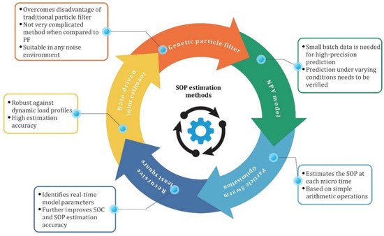
Figure 7. Schematic of different SOP estimation methods.
Table 3. Summary of SOP estimation control techniques.
| Control Approach | Significant Outcomes | Reference | Maximum Error |
|---|---|---|---|
| Model-less FLC | Predicts SOP with no prior knowledge of SOH and is also robust to errors in SOC estimates | [83] | - |
| Improved genetic particle filter (IGPF) | More efficiency and practicality than other algorithms with complex calculations | [79] | 3% |
| Polarization voltage model | Simple structure model which requires only small-batch primary data to realize high precision SOP estimation | [80] | 5% |
| Adaptive EKF | A joint estimator of SOC and SOP shows higher estimation accuracies in new, as well as aged, batteries | [84] | <2.5% |
| Extremum-seeking algorithm | It considers both current and voltage limitations of the battery providing a two-level estimation of battery peak power capacities | [81] | 1.44% |
| Genetic algorithm | Gives improved SOP estimation accuracy given that there are errors in SOC estimation | [85] | <1% |
| HPSO algorithm | It emphasizes accuracy along with a deep analysis of the constraints in developing a battery management strategy | [86] | 1.34% |
| PSO-UKF method | It gives high accuracy estimation and is robust in performance | [82] | - |
4. Battery Cell-Balancing
The SOC of each cell is crucial in determining whether an imbalance in the battery string exists or not. A cell imbalance occurs if there exists any difference between the SOC or voltage of the cells. This in turn adversely affects the aging characteristics of the battery and lowers its efficiency [87]. The imbalance is imposed by either manufacturing errors or non-uniform temperature distribution among the cells [15]. Overcharging and over-discharging are two common negative effects of voltage imbalance in batteries. Overcharging, particularly in Li-ion batteries, lowers the lifetime, decomposes battery electrolytes, compromises battery safety and initiates dendrite formation. Moreover, deep discharging leads to oxidization of copper electrodes [16] which may lead to battery explosion or fires in some cases [87]. These undesirable events demand the implementation of cell-balancing strategies to protect the battery pack against potential harm and thus increase its lifetime [88,89]. For a dynamic application, such as ESS in EVs, where reliability and safety are of the utmost importance, maintaining the voltage of cells at the same level becomes a prerequisite for the efficient operation of EVs. The function of the cell-balancing module in a BMS in an EV is to avoid overcharging and deep discharging of battery cells by maintaining an equal charge in all the cells of the battery. Several investigations have been performed in the domain of cell-voltage-balancing in EVs and several methods have been proposed to date. The generalized architecture of the cell-balancing module in the BMS is schematically presented in Figure 12.
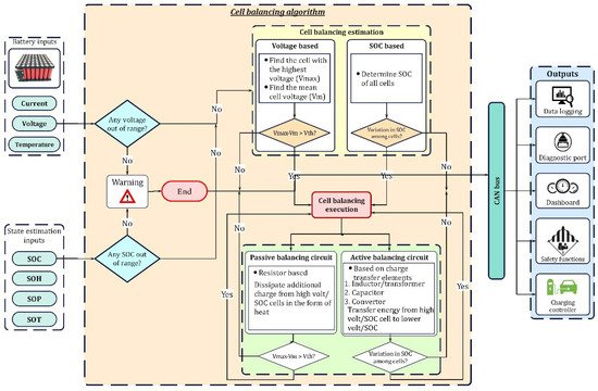
Figure 8. Generalized internal architecture of cell-balancing module.
4.1. Cell-Balancing Architecture along with Workflow
From the state estimation module and battery pack, the SOC and voltage of all cells are taken as inputs. Different algorithms, such as voltage-based or SOC-based, are employed for the estimation approach. If there is a requirement to balance cells, then a suitable balancing topology, either passive or active is implemented. These topologies are expounded in the subsequent sections. Once the balancing cycle is accomplished, the control algorithm will again check for the need for balancing. The controller will end the process if balancing is achieved, or else the same procedure is repeated until all the cells are balanced. The cell-balancing module is in constant communication with other modules also inside the BMS, such as the charging controller and the safety management system. In the event of danger, the safety management module executes suitable safety functions to avoid severe causalities and communicates the fault to the user via a diagnostic port and on the dashboard. To ensure the voltage-balance among cells, several topologies have been proposed which are discussed in the following sections.
4.2. Classification of Cell-Balancing Topologies
From the cell-balancing architecture, based on the input parameters, estimation of the requirement for cell-balancing can be performed, either based on cell voltage or the SOC of individual cells [90]. Generally, topologies for balancing cell voltages in EVs fall into passive and active cell-balancing categories. In passive balancing, an additional charge from the high-voltage/SOC cell is dissipated into heat via resistors [91], whereas, the charge from the higher voltage/SOC cell is transferred to lower voltage/SOC cell(s) in active balancing. The passive topologies are simple and easy to implement but offer less balancing accuracy and involve a higher balancing time [92]. The active balancing topologies can be classified based on charge transfer elements [93,94] which use inductors/transformers, capacitors, and converters as charge-transferring elements. When compared to passive techniques, active methods are more accurate and render faster balancing; however, circuit complexity and the associated cost are major downsides of active topologies. The existing passive and active balancing topologies are critically reviewed in subsequent sections.
4.3. Passive Balancing Topologies
Passive balancing topologies remove the excess energy from higher voltage/SOC cells in the form of heat, via resistors or other heat-dissipating elements. These methods are simple to control, least costly, and small; nevertheless, loss of excess charge requires efficient thermal management for controlling the overheating of cells/modules. Applications of fixed shunting resistors [95] are limited to lead-acid and nickel-based batteries as they can be overcharged, while Li-ion batteries cannot be overcharged. On the other hand, switched shunting resistors [96] can be used in Li-ion batteries. Moreover, they can attain faster balancing than fixed-shunting resistors and ICE. ICE bypasses the current from high-voltage cells and solves the issue of drawing regulated current into shunt elements, and, thus, minimizes the energy losses present in shunting resistor topologies [97]. Dissipating energy using MOSFET [98,99] is performed only at the end of the charging process; hence, energy losses are less than with the shunting resistor topology but the balancing time is still higher. In addition, these topologies are suitable only in the charging phase; they are not helpful when cells are being discharged, which is a serious drawback. Passive techniques can be used in HEV applications [100], whereas their implementation in EVs is infeasible because it could demand a costly design with a more effective thermal management system due to high energy losses. To overcome such issues, active cell-balancing topologies are developed. The existing passive cell-balancing approaches are described in Figure 9.
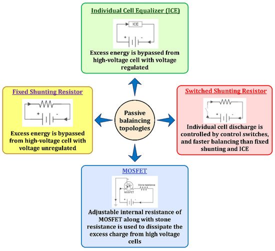
Figure 9. Summary of passive cell-balancing topologies.
4.4. Active Balancing Topologies
Passive topologies are inefficient owing to high energy losses occurring in heat-dissipating elements. Hence, active cell-balancing topologies are developed to tackle this issue. Based on the charge transfer element, active topologies that can be used in EVs use different elements, such as inductor/transformer, switched-capacitor and converter.
4.4.1. Inductor/Transformer-Based Topologies
In these topologies, energy from high-voltage cells to low-voltage cells is transferred by either inductors or transformers. Based on the number of inductors/transformers used in the balancing circuit, several configurations are proposed. Single inductor configuration use only one inductor to transfer energy from a high-voltage cell to the entire battery pack which reduces magnetic losses [101]. Multi-inductor topologies transfer energy between neighboring cells (cell-to-cell) due to which it takes more balancing time than a single-inductor typology which renders the system inefficient for applications using large battery strings, such as EVs [102,103]. Transformer-based balancers are classified into three main categories: single-winding, multi-winding, and multiple transformers [104]. The single-winding transformer uses a single winding on both primary and secondary sides to achieve cell-to-pack/pack-to-cell charge transfer [105]. It provides an optimized path for power transfer to minimize power losses. These cell-to-pack/pack-to-cell approaches have been proven effective for balancing cell voltages, but due to the presence of energy overlap and high-voltage stresses, the balancing efficiency is compromised. To overcome this hurdle, direct cell-to-cell topologies are introduced. In the multi-winding transformer (MWT) topology, single winding occurs on one side and multi-windings are given on the other side. The number of windings should be the same as the number of connected cells. MWT may adopt the forward and/or fly-back conversions to attain faster balancing [106,107]. The multiple-transformer topology transfers energy from the highest charged cell to the battery pack or vice-versa [108]. One concern with transformers is the losses occurring in their windings. To curtail these losses, separate demagnetizing circuits are used, which makes the system bulky and expensive. To overcome these issues, a modularized automatic equalizer (MAE) is used which achieves automatic demagnetization through complementary structures of secondary windings, thereby eliminating demagnetizing circuits [109,110]. It can transfer energy from any cell to any cell in the battery pack. The cell-to-pack/pack-to-cell and direct cell-to-cell architecture transfer charge at relatively higher efficiency than other architectures [87]. In comparing the aforesaid methods, the single-inductor has proven to be efficient due to lesser magnetic losses and remarkable balancing speed; however, its complex control, more sensing elements, need for a filter capacitor, and stresses acting on switches/MOSFETs, pose some difficulties when used in Li-ion batteries. Multiple transformers can provide faster balancing speed, better modularity than MWT, and can be easily used for long battery strings. Furthermore, MWTs can balance the cells only in the charging phase [111]. Moreover, retaining symmetry in the transformer’s structure becomes arduous when the number of windings exceeds a certain number and current stresses acting on primary side-switches in MWTs are high. Hence, multiple transformers are preferred over MWTs in EVs. On the other hand, the modularized structure uses a simple control scheme whilst maintaining all the benefits offered by other topologies and provides freedom to be used for long battery strings as well. Thus, it tends to outmatch other topologies which makes it well-suited for balancing Li-ion batteries in EVs. Despite faster balancing and high efficiency, intelligent control and high cost are huge challenges for inductor-based topologies. Therefore, a cost-efficient approach is required. Hence, switched-capacitors are an economical solution compared to inductors. The research studies on cell-balancing using inductors/transformers are summarized and presented in Table 4. Their respective merits and demerits are outlined in Figure 10.
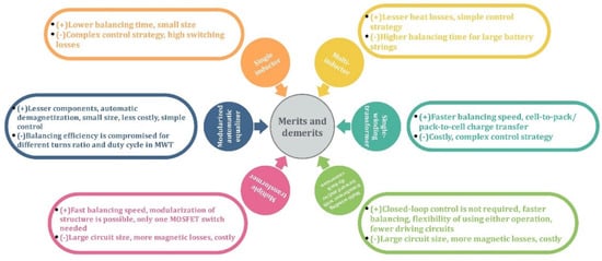
Figure 10. Merits and demerits of inductor/transformer-based cell-balancing topologies.
Table 4. Review of inductor/transformer-based cell-balancing topologies.
| Balancer | Salient Features | No. of Elements | Ref | |||
|---|---|---|---|---|---|---|
| L | T | S | D | |||
| Single inductor | Reduced magnetic losses | 1 | 0 | 2 n | 0 | [101] |
| Multi-inductor |
|
n − 1 | 0 | n + 2 | 0 | [102,103] |
| Single-winding transformer |
|
0 | 1 | n + 2 | 0 | [105] |
| Multi-winding transformer |
|
0 | 1 | n | 0 | [106,107] |
| Multiple transformer |
|
0 | n | 1 | n | [108] |
| Modularized automatic equalizer |
|
0 | m | mn | 0 | [109,110] |
n = number of cells; m = number of modules; L = inductor; T = transformer; S = MOSFET switch; D = diode.
4.4.2. Switched Capacitor (SC)-Based Topologies
Numerous economical topologies based on the number of capacitors and switches have been developed. The conventional SC transfers charge among neighboring cells [112,113]. The single SC provides higher balancing speed since it transports energy from high-voltage cells to low-voltage cells directly [114]. The double-tiered SC (DTSC) uses additional rows to enable charge transfer between non-adjacent cells [115,116]. It attains faster balancing than the conventional SC. In modularized SCs, the battery uses a modular structure and switched-capacitor approach to achieve cell-to-cell and module-to-module balancing [117,118]. The modularity enhances balancing speed over conventional SCs. The chain-structured SC (CSSC) optimizes the balancing speed by connecting the first cell in the battery string with the last cell, thus reducing the distance between the two farthest cells by half. However, higher voltage stresses on capacitors and switches make them inappropriate for large battery strings [119]. The switched coupling capacitor gives flexibility for a modular structure along with faster balancing [120]. The energy loss is minimized in a series-parallel SC by maintaining constant charge throughout the balancing process; however, the use of more switches and capacitors per cell increases switching losses [121]. The optimized SC can achieve the same balancing speed as series-parallel SC and CSSC without using additional capacitors and switches [122]. Although the aforesaid topologies can maintain high balancing speed, high switching losses are a major downside. Therefore, resonant SCs, such as the quasi-resonant SC and the chain-structured resonant SC (CSRSC) have been developed to attain a zero voltage gap (ZVG) between cells and zero current switching (ZCS) [123,124]. Resonant SCs achieve a reduction in switching losses through ZCS whilst enhancing the balancing speed. Comparing the topologies, switching losses and large balancing time make the conventional SC the least efficient. The DTSC, modularized SC, CSSC, coupling SC, and series-parallel SC, attain faster balancing than the conventional SC. The DTSC balancing speed drops when the number of cells in series increases. Moreover, they tend to cause a higher balancing time than inductors and transformers, making them less efficient in terms of balancing speed. Despite the shortcomings, the SCs referred to have several merits that outweigh their demerits, such as low current stresses acting on MOSFETs, lesser controller complexity, fewer sensing elements, and, above all, the ability to effectively balance the cells during both charging and discharging phases, unlike some inductor and transformer-based topologies. The ability of the optimized SC to achieve balancing as rapidly as series-parallel SCs and CSSCs, without having to use extra switches and capacitors, strengthens its overall balancing efficiency. The resonant SCs ensure lesser switching losses and faster balancing speed making them a highly efficient SC approach that can be used for cell-balancing in EVs. The existing literature indicates that resonant and modularized configurations have become a strong focus of research and are showing rapid development. Moreover, the recently developed star-structured LC resonant switched capacitor and the switched capacitor with modularized chain structure showed efficiencies of 98.7% [125] and 98.8% [126], respectively. However, further investigation for reducing the balancing speed of SCs is still required to ensure efficient performance in EVs. Nowadays, different converters are used for mitigating the issue of poor balancing speed. The major outcomes derived from research on SCs are encapsulated in Table 5. The merits and demerits pertaining to SC-based topologies are demonstrated in Figure 11.
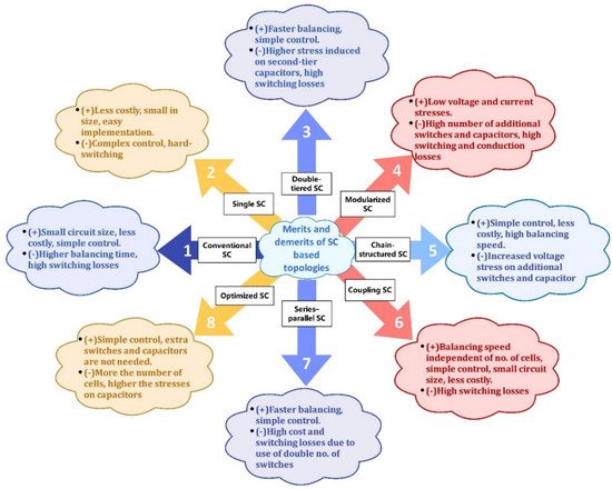
Figure 11. Merits and demerits of SC-based cell-balancing topologies.
Table 5. Review of switched-capacitor-based cell-balancing topologies.
| Balancer | Salient Features | No. of Elements | Ref | ||
|---|---|---|---|---|---|
| C | L | S | |||
| Conventional SC |
|
n − 1 | 0 | 2 n | [112,113] |
| Single SC |
|
1 | 0 | n + 5 | [114] |
| Double-tiered SC |
|
n + 1 | 0 | 2 n | [115,116] |
| Modularized SC |
|
m (n − 1) +1 | 0 | 2 mn | [117,118] |
| Chain-structured SC |
|
n | 0 | 2 n | [119] |
| Coupling SC |
|
n | 0 | 2 n | [120] |
| Series–parallel SC |
|
n | 0 | 4 n | [121] |
| Optimized SC |
|
n | 0 | n | [122] |
| Quasi-resonant SC converter |
|
4 n − 4 | n − 1 | 2 n − 2 | [123] |
| Chain-structured resonant SC |
|
n | n | 2 n | [124] |
n = number of cells; m = number of modules; L = inductor; C = capacitor; S = MOSFET switch.
4.4.3. Converter-Based Topologies
Power converters are widely used to transfer charge between high-voltage and low-voltage cells in EV batteries. Nevertheless, one major drawback is their associated cost and complexity in design and implementation. The conventional PWM-controlled converter utilizes a pulse-width modulation (PWM) signal that operates switches to transfer charge among neighboring cells [127]. Their charge transfer efficiency is higher; nonetheless, they involve a higher balancing time and require complex control. The Ćuk converter [128,129] also works on the principle of PWM for transferring charge from one cell to another. It can be viewed as an upgrade of the conventional PWM-controlled converter since it gives lower voltage or current stresses on switches than in the conventional configuration. However, it uses a capacitor to store energy and supply it to low-charge cells, unlike the conventional PWM-controlled converter [130]. It is more efficient than a conventional buck-converter because of its ability to provide ripple-free input current naturally [131,132]; the buck-converter has to use one extra inductor for providing ripple-free current which compromises its efficiency due to additional core and copper losses, size, cost, and weight. The fly-back converter achieves cell-to-pack balancing during the charging phase to avoid overcharging of cells, while it achieves pack-to-cell-balancing during the discharging phase to preclude over-discharging [133,134]. Here, periodic charging/discharging of cells enhances the charge distribution efficiency. Moreover, its suitability for modularization makes it more favorable for EV applications. Switching losses can be reduced by using the PWM signal to control the balancing circuit [135]. The Ramp converter uses a single secondary winding for two neighboring cells; as a result, magnetic losses and circuit size are reduced considerably over MWTs—nonetheless, its design is complicated [136]. Buck and boost converters are used to step down and raise the DC voltage, respectively [137]. They provide enhanced performance in terms of balancing speed and modularization over Ramp and Ćuk converters. The selective balancing of cells, irrespective of their positions, enables direct energy transfer to least-charged cells using a switched-matrix with a DC-DC converter [138]. It offers faster balancing speed than other converters and SCs and ease of modularization. However, it experiences high-voltage stresses when the battery string length increases. The full-bridge converter has a higher charge-transfer efficiency than many converters since it can charge/discharge cells at different currents according to their needs [139]. This ability minimizes the energy losses that would occur otherwise. Moreover, the use of a full-bridge configuration enhances the balancing speed, making it well-suited to EV application. It is used in EVs as a DC-DC converter and in plug-in HEVs for AC-DC conversion and balancing [140]. QRLCC-BDDC exploits the benefits of a quasi-resonant LC converter and boost DC-DC converter [141]. QRLCC transports energy with ZCS and BDDC regulates balancing currents according to the voltage difference. This method solves the issue of obtaining ZVG between the cells due to a voltage drop across power devices existing in current direct-cell-to-cell topologies. When compared with other direct-cell-to-cell topologies, this topology affords higher balancing current, reduced circuit size, cost, and weight, along with the added benefits of ZVG and ZCS. Thus, QRLCC-BDDC converters show high potential for being used in long battery strings in EVs. From the discussion provided in this section, it can be seen that most of the converters achieve the benefit of easy modularization at the expense of complex control strategies and high cost. Hence, it becomes vital to maintain a balance between the proposed merits and demerits depending upon the application to ensure an efficient converter. Currently, resonant, buck or/and boost, fly-back converters and other modularized configurations are employed commercially for battery cell-balancing in EVs [140]. The salient outcomes of research studies related to different converter-based topologies are summarized and presented in Table 6. The merits and demerits of converter configurations are given in Figure 12.
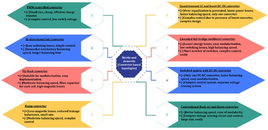
Figure 12. Merits and demerits of converter-based cell-balancing topologies.
Table 6. Review of converter-based cell-balancing topologies.
| Balancer | Salient Features | No. of Elements | Ref | |||||
|---|---|---|---|---|---|---|---|---|
| R | C | L | T | S | D | |||
| Conventional PWM controlled converter |
|
0 | 0 | n − 1 | 0 | 2 n − 2 | 0 | [127] |
| Bidirectional Ćuk converter |
|
0 | n − 1 | 2 n − 2 | - | 2 n − 2 | 0 | [128,129], [131,132] |
| Fly-back converter |
|
0 | 0 | 0 | 2 n | n | 2 n | [133,134] |
| Ramp converter |
|
0 | n | n/2 | 0 | n | n | [136] |
| Conventional buck or/and boost converter |
|
0 | 0 | n − 1 | 0 | 2 n − 2 | 0 | [137] |
| Switched matrix with DC-DC converter |
|
0 | 0 | 0 | 0 | 2 n | 0 | [138] |
| Cascaded full-bridge multilevel converter |
|
1 | 0 | 0 | 0 | 4 n | 0 | [139] |
| Quasi-resonant LC and boost DC-DC converter |
|
0 | 2 | 0 | 2 | Relay—4 n MOSFET—5 |
5 | [141] |
n = number of cells; m = number of modules; R = resistor; L = inductor; C = capacitor; T = transformer; S = MOSFET switch; D = diode.
This entry is adapted from the peer-reviewed paper 10.3390/en15124227
This entry is offline, you can click here to edit this entry!