Marine Exhaust Gas Treatment Systems: History
Please note this is an old version of this entry, which may differ significantly from the current revision.

In the present work, the contemporary exhaust gas treatment systems (EGTS) used for SOx, PM, and NOx emission mitigation from shipping are reviewed. Specifically, after-treatment technologies such as wet scrubbers with seawater and freshwater solution with NaOH, hybrid wet scrubbers, wet scrubbers integrated in exhaust gas recirculation (EGR) installations, dry scrubbers, inert gas wet scrubbers and selective catalytic reduction (SCR) systems are analyzed. The operational principles and the construction specifications, the performance characteristics and the investment and operation of the reviewed shipping EGTS are thoroughly elaborated. The SCR technology is comparatively evaluated with alternative techniques such as LNG, internal engine modifications (IEM), direct water injection (DWI) and humid air motor (HAM) to assess the individual NOx emission reduction potential of each technology. Detailed real data for the time several cargo vessels spent in shipyards for seawater scrubber installation, and actual data for the purchase cost and the installation cost of seawater scrubbers in shipyards are demonstrated. From the examination of the constructional, operational, environmental and economic parameters of the examined EGTS, it can be concluded that the most effective SOx emission abatement system is the closed-loop wet scrubbers with NaOH solution which can practically eliminate ship SOx emissions, whereas the most effective NOx emission mitigation system is the SCR which cannot only offer compliance of a vessel with the IMO Tier III limits but can also practically eliminate ship NOx emissions.

  • exhaust gas treatment systems
  • IMO 2020 global sulfur cap: IMO NOx Tier II/III limits
  • scrubbers
  • selective catalytic reduction (SCR)

1. Introduction

The main gaseous constituents of exhaust gases generated by marine diesel engines are carbon dioxide (CO2), water vapor (H2O), nitrogen (N2) and oxygen (O2) [1]. As known, in-cylinder available nitrogen and oxygen react at high temperatures in the reaction zone of combustion flame, generating nitrogen oxides (NOx) which are primarily a mixture of nitrogen monoxide (NO) and nitrogen dioxide (NO2) with the latter in small quantities [1]. In addition, marine diesel engines burning sulfur-containing fuels such as heavy-fuel oil (HFO) emit sulfur oxides (SOx). Marine diesel engines are also significant emitters of carbon monoxide (CO), total unburned hydrocarbons (THC) and particulate matter (PM) [2]. Hence, marine diesel-emitted CO2, NOx, CO, THC and SOx are the main gaseous species in conjunction with particulate emissions (PM) that have the highest negative impact on the environment and on human health [3]. For this reason and with concern for maritime SOx emissions, the International Maritime Organization (IMO) has issued specific limits for marine fuel sulfur content to control marine diesel-emitted SOx values. The IMO fuel sulfur limits are higher on a global level compared to the ones specified for SOx Emission Controlled Areas (SECAs) [3]. According to IMO Regulation 2.9 [3], sulfur oxides and PM emission controls apply to all fuels, on-board combustion systems, including main and auxiliary engines with boilers and inert gas generators. Previously mentioned controls include those that are implemented inside Emission Control Areas (ECAs), which are targeted to curtail SOx and PM emissions, and those that are implemented globally outside ECAs and are attained by controlling the maritime fuel sulfur percentage as it is bunkered and used on-board. As evidenced from IMO Regulations 14.1 and 14.4 [3], fuel sulfur limits, which are provided as %m/m, have undergone specific modifications during recent years. The chronological evolution of the sulfur content of maritime fuels, both globally and in SECAs, is given in Table 1 [2].
Table 1. Marine fuel sulfur contents that have been legislated by the International Maritime Organization (IMO) according to the MARPOL Annex VI and are effective in both SOx Emission Control Areas (SECAs) and globally. (Table was genuinely generated using data from ref. [3]).
The establishment of the IMO Global Sulfur Cap of 0.5% on 1 January 2020 changed the scenery of fuel supply and availability [3]. Though the technological solutions to comply with the IMO Global Sulfur Cap are numerous, the selection of a certain solution is quite difficult because it is based on various technical, environmental and economic criteria [3]. In addition to the maritime fuel sulfur limit of 0.5% which is implemented globally, there is an additional requirement by the IMO for a 0.1% maritime fuel sulfur limit in SECAs such as the North American coastline, the Caribbean Sea, the North Sea and the Baltic Sea [3]. It is also worth mentioning that maritime vessels using exhaust after-treatment systems are allowed to use high sulfur fuel oil (HSFO) [4].
To fulfill the limitations of fuel sulfur content as dictated by the IMO [3] both inside and outside SECAs, ships can operate with low sulfur conventional fuels that comply with the IMO fuel sulfur regulations. Alternatively, ships can operate with alternative fuels that contain extremely low sulfur or do not contain sulfur [6]. Such alternative fuels that have been used in the maritime industry are liquefied natural gas (LNG), biofuels, dimethyl ether (DME), methanol and ethanol, ammonia and hydrogen, which are fuels that do not contain sulfur [6]. However, the use of these alternative fuels in ships, though contributing significantly to the minimization of SOx emissions, is accompanied by many drawbacks such as their bunkering availability, high production cost, variable on-board storage capacity and others. Hence, taking into consideration that the use of high sulfur fuel will be continued because it is compliant with existing marine diesel engines and existing bunkering and on-board infrastructure and also taking into consideration the IMO’s fuel sulfur limits inside and outside SECAs, one of the most prominent ways to ensure that existing and future vessels comply with the IMO’s SOx and PM emission regulations is for them to use exhaust gas treatment systems (EGTS) [7].
The main exhaust after-treatment systems that are utilized nowadays in maritime vessels are comprised of wet scrubbers operating either as open-loop systems with seawater as the scrubbing medium or as closed-loop systems with aqueous solution of NaOH as the scrubbing medium [8]. The careful examination of the literature has shown that various solutions have been suggested to curtail NOx emissions generated from marine engines and combustion systems and to comply with the IMO Tier II limits that are effective globally. According to a recent study, the available marine NOx reduction technologies for compliance with Tier III NOx limits were amended. Furthermore, this study examined the operational principles and progress of various NOx reduction technologies and thoroughly assessed and criticized the advantages and the disadvantages of these technologies. As witnessed, the implementation of exhaust gas recirculation (EGR) technology can lead to marine engine operation compliant with Tier III NOx limits without taking into consideration the increased engine fuel consumption. EGR is one of the most promising and well-proven NOx-controlling technologies, which has proven quite effective over the years in curtailing in-cylinder NOx formation in marine internal combustion engines. Though EGR is highly effective in reducing NOx formation inside the cylinders of marine engines, it results in a significant deterioration of brake-specific fuel oil consumption (SFOC) and of soot emissions. For this reason, a detailed examination of the impact of various EGR percentages on NOx, SFOC and soot emissions is required prior to its implementation in marine diesel engines. In addition, it was shown that the application of SCR systems in the exhaust of marine engines and combustion systems is the most effective way to achieve the IMO NOx Tier III values. However, despite the continuous optimization of SCR units, the problem of catalyst progressive pollution seriously narrows their broad implementation. Another important issue for the in-cylinder control of pollutant emissions from marine engines is the successful turbo matching with the engine because it allows the feeding of the engine with adequate amounts of intake air at all engine loads. Successful turbo matching is a crucial factor that affects the selection of either a high pressure or a low-pressure SCR system. Significant NOx reduction rates can be attained with natural gas marine engines, but additional technologies are required for natural gas engines to comply with NOx Tier III limits. Other technologies such as variable valve timing and Miller cycle, two-stage turbocharging and fuel/water emulsion can contribute significantly to the control of NOx values emitted from marine engines, but these technologies are scarcely used independently, almost always being used in conjunction with other technologies instead. These technologies can be used in combination with EGR, SCR and natural gas technologies for the optimization of marine engine fuel economy and polluting behavior. Hence, the most effective and promising technology for the direct compliance of marine engines with NOx Tier III standards is the exhaust gas treatment using SCR technology [9]. Recently, Lion et al. [10] examined the operational principles, the effectiveness and the advantages and disadvantages of internal measures for NOx reduction from marine engines and exhaust gas cleaning technologies such as SOx scrubbers and SCR systems. They found that scrubbers are highly effective in reducing SOx emissions from marine combustion systems, especially in the case of alkali dosage control, and the SCR system is the most effective NOx reduction technology for commercial vessels. Similar conclusions were drawn in the recent review studies for marine emission reduction strategies published by Ni et al. [11] and Deng et al. [12].

2. Operational Principles and Key Characteristics of Marine Exhaust Gas Treatment Systems

2.1. General Description

According to the literature [29], two basic types of treatment systems of exhaust gases generated from marine compression ignition engines and from marine combustion systems, e.g., exhaust gas boilers, exist. These two basic exhaust gas treatment systems are used for SOx and particulate matter (PM) mitigation. Details about both are listed below:
  • Aqueous—wet exhaust gas treatment and SOx and PM curtailment systems, or wet scrubbers.
  • Dry flue gas treatment and SOx mainly reduction systems (dry scrubbers).
  • The aqueous SOx and PM mitigation systems are divided into three categories [30]:
  • Open circuit or open-loop aqueous scrubbing systems, usually based on the use of seawater as flue gas scrubbing and SOx and PM mitigating medium in specially designed counterflow heat exchangers that are called scrubbers [31].
  • Closed circuit or closed-loop aqueous scrubbing systems usually based on the use of an aqueous solution of fresh water and alkaline medium (usually sodium hydroxide (caustic soda), NaOH) as exhaust gas scrubbing, and SOx and PM mitigation medium in specially designed counterflow heat exchangers [32].
  • Aqueous hybrid scrubbing systems which can function as either open-loop systems with seawater or closed-loop systems with aqueous solution of NaOH [33].
Moreover, exhaust gas treatment systems exist that are modified versions or applications of the previously mentioned SOx and PM mitigation systems:
  • The aqueous exhaust gas treatment and scrubbing systems (scrubbers) that operate as sub-systems of exhaust gas recirculation (EGR) installations in marine engines. As known, EGR is used in marine engines for the reduction of the in-cylinder NOx formation rate. Hence, the integrated EGR systems equipped with wet scrubbers are primarily used to mitigate NOx formation inside the cylinders through exhaust gas recirculation, and they employ wet scrubbers to curtail SOx and PM emissions. The employment of the aqueous gas treatment systems of this category, besides SOx and PM mitigation, result in the curtailment of the fouling and corrosion phenomena of the marine diesel due to aqueous exhaust gas cleaning [34,35].
  • Inert gas aqueous systems that use small-size aqueous SOx and PM mitigation systems to clean and convert exhaust gas to inert gas can further be used for tanker evacuation [36].
Marine aqueous exhaust gas treatment and mainly SOx reduction systems have been commercially dominant. Since 2011, dry exhaust gas treatment and SOx mitigation systems have been commercially available from only one manufacturer. As can be realized, the main objective of both aqueous and dry exhaust gas treatment systems is the sorption and the rejection of SOx emissions from exhaust gases generated from marine combustion systems. One additional virtue of these systems is the sorption of particulate emissions of marine-generated exhaust gases, thus reducing the heavy metals, the soot, the polyaromatic hydrocarbons (PAH) and the sulfur contained in the particulate matter [37].
The main exhaust gas treatment technology implemented in marine diesel engine exhaust to reduce NOx emissions, is the selective catalytic reduction (SCR). SCR technology operates by combining the use of ammonia (NH3), which is typically produced from a urea solution, with one catalyst that is placed on a ceramic monolith to convert nitrogen oxides (NOx) to nitrogen (N2) and water (H2O).

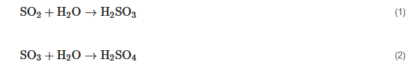
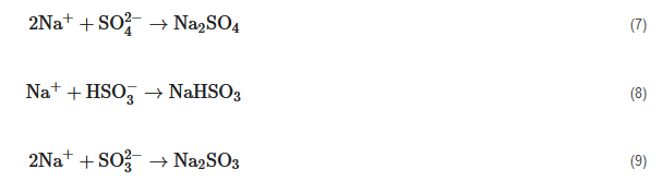
2.2. Wet Exhaust Gas Cleaning and SOx Reduction Systems with Seawater or with Caustic Soda (SOx Scrubbers)

Before describing the operation principles and the constructional peculiarities of aqueous SOx mitigation after-treatment systems, it is very important to delineate the chemistry of aqueous sorption of sulfur oxides from marine-generated exhaust gases. SOx containment chemistry is almost the same for all aqueous flue gas treatment systems, and it can be described from the following chemical reactions [39]:
The sulfurous acid will be ionized in the presence of water with regular acidity, formulating bisulfite and sulfite ions according to the following reactions [40]:
Inside seawater, which contains oxygen, the sulfite ions will be oxidized and provide sulfate roots:
In addition, the sulfuric acid which is produced from the SO3 fraction that exists in exhaust gases will undergo pertinent chemical reactions with the previous ones, providing sulfate roots and additional acidity (H+ ions) [41]:
The reduction of pH (acidity increase) that results from the previously mentioned chemical reactions which are conducted during the scrubbing process of exhaust gases, is inactivated mainly by the physical alkalinity of the seawater providing satisfactory freshwater quantities. The natural alkalinity of the seawater is mainly the result of the presence of the natural bicarbonate root (HCO3) [42].
The basic scrubbing chemistry of SOx emissions from aqueous exhaust gas treatment systems that are using fresh water is almost the same as the one of the seawater wet scrubbers. However, in this case, the absence of a natural alkaline medium in the water should be compensated for by the addition of a proper alkaline medium. Most commercially available wet scrubbers use sodium hydroxide, NaOH (or caustic soda), as an alkaline SOx capture medium.
The sodium hydroxide appears with the form of ions in an aqueous solution as described by the following chemical reaction:
Similar to the seawater exhaust gas treatment, the exhaust gas treatment with fresh water (depending on the solution pH) will oxidize exhaust gas containing SO2 and SO3 ions and convert them into sulfate ions, generating in parallel additional acidity (H+ ions). In the presence of caustic soda, the roots of sulfuric, bisulfite and sulfite salt will create a mixture of sodium sulfate, sodium bicarbonate and sodium sulfate [36]:
The hydroxide ions will inactivate the produced acidity by reacting with H+ ions and produce fresh water:
An aqueous exhaust gas treatment installation is basically comprised of the wet scrubber which is placed in the exhaust of one or more marine internal combustion engines, and which is followed, in the majority of the cases, by an effluent water treatment unit and by an effluent water discharge unit. 
The aqueous exhaust gas treatment and mainly the SOx mitigation system or the SOx scrubber is a specially designed heat exchanger with extended exchange area of mass, momentum and heat between the flue gas stream and the aqueous scrubbing medium. After extensive and detailed experimental studies, numerous manufacturers have concluded that marine SOx scrubbers are the optimum solution for the treatment of exhaust gases and the dramatic curtailment of SOx emissions from marine combustion systems [36].
Gregory and West [32] who provided information about the constructional specifications and the operational data of seven aqueous SOx mitigation systems have found that three out of the seven systems have the ability to change operating mode from open-loop systems with seawater as scrubbing medium to closed-loop systems with fresh water, and with the addition of SOx, they can capture chemicals. (At least one of these systems uses a small amount of NaOH during its open-loop operation with seawater to avoid extensive corrosion of the mechanical equipment). Two aqueous SOx scrubbing systems manufacturers use exclusively closed-loop systems, and two corresponding manufacturers use only seawater during the exhaust gas scrubbing process. Extremely detailed technical specifications for SOx mitigation scrubbers are not available in the literature since scrubber manufacturers are reluctant to provide all the technical details. However, there is a variation from systems that guide the exhaust gas stream through an inlet duct to a swallow water tank to cyclonic scrubbing systems, which achieve SOx mitigation through centrifugation and scrubbing of exhaust gases [36]. Despite that, the SOx capture rate appears to be similar between different constructional layout scrubbers, although the mitigation rate of PM emissions varies significantly with the configuration of the SOx and PM scrubber. This fact motivated specific scrubber manufacturers to examine various pre-processing exhaust gas treatment systems [32]. These pre-processing initiatives comprise injection nozzles and venturi-type adjustable nozzles. The use of venturi nozzles results in flow strangulation. leading to lower outlet pressure and higher outlet exhaust gas velocities. These parameters on a combinatory basis result in the increase of turbulence levels and significantly enhance the SOx and PM emissions capture rate [36]. However, the increased pressure strangulation in venturi nozzles can lead to high values of back pressure at the marine engine exhaust; hence, it can disrupt the critical balance of pollutant mitigation degree at optimum levels with a parallel compromise of the operational efficiency and fuel consumption of marine diesel engines. The contemporary technical challenges that SOx and PM scrubbers face are the following according to the MEPC 56/INF. 5/Annex 1 2007 [36]:
  • The preservation of exhaust gas buoyancy phenomenon (i.e., the avoidance of excess temperature reduction of exhaust gases during their scrubbing process by the aqueous medium).
  • The simultaneous minimization of the space captured and the weight and the energy consumption by the SOx and PM mitigation aqueous gas treatment system.
  • The minimization of the pressure drop of the exhaust gas stream.
  • Hot corrosion avoidance of the SOx scrubber constructional elements from exhaust gases that contain sulfur and possibly acid sulfate roots.
  • The avoidance of exhaust gas vapor condensation and appearance of water droplets at the SOx and PM scrubber outlet.
The on-board aqueous SOx scrubbers have three different waste fluid streams [43]:
  • The effluent water from the scrubber which is either ejected to the sea or guided to an on-board wastewater treatment plant.
  • The heavy residues that are rejected from the on-board wastewater treatment plant or from the freshwater recirculation process.
  • The flue gases that contain the remaining pollutant species which were not captured from the aqueous flue gas treatment process.
One of the most critical questions regarding the aqueous exhaust gas scrubbing process and SOx capture is the rejection of the effluent water from the scrubbing process. Gregory and West [32] tried to address this question and suggested that the aqueous exhaust gas treatment systems with seawater or caustic soda are not highly effective regarding SOx capture. However, they are effective in capturing particulate emissions and lubricant oil with capture rates more than 80%. Hence, the on-board existence of an effluent water treatment installation is essential. This effluent water treatment installation will have the ability to capture and reject the particulate matter and lubricant oil that are carried in processed exhaust gases [44]. Effluent water flows from seawater scrubbers and scrubbers operating with an aqueous solution of NaOH are quite different, both in their composition and quantity. A seawater scrubber will reject the total amount of effluent water in all cases, except for a small quantity of water that is drawn from the residue stream in operational wastewater process installations. The caustic soda scrubber under normal conditions could reject a small amount of impure water to counterbalance the pollutant species that are contained in the scrubbing process water. The impure water rejection rates in both types of scrubbers, i.e., open-loop and closed-loop, will vary depending on the design of the exhaust gas scrubber. However, for simplicity reasons, generally accepted values of impure water rejection rates can be found in MEPC 58/23 Annex 16 of 2008 [45]:
  • The impure water rejection rate from a SOx scrubber with seawater as the scrubbing medium is 45 m3/MWh.
  • The impure water rejection rate from a SOx scrubber with caustic soda varies from 0.1 to 0.3 m3/MWh (The indicative recirculation rate is 20 m3/MWh).
According to the MEPC 56/INF.5/Annex 1 of 2007, three different fluids are present in SOx scrubbers [46]:
  • Exhaust gases that are generated from marine diesel engines (Exhaust gases are produced from the combustion of intake air with fuel. Lubricant oil can also be present in exhaust gases depending on the engine status and the operational conditions).
  • Seawater or fresh water with NaOH which are used for scrubbing exhaust gases.
  • Impure water which may contain combustion products and chemical additives.
In addition to the previously mentioned sources, there will be contributions to the impure water of the exhaust gas scrubbing process from the wear of engine metal parts and possibly from corrosion products, e.g., seawater corrosion products. In cases where the marine SOx scrubbers are equipped with impure water processing units, a stream of heavy residues will be produced in parallel with the discharge of processed water. This includes SOx scrubbers with seawater where the effluent water stream should be processed and systems where the small stream of impure water discharged from a freshwater scrubber will be processed by any processing installation [47]. Heavy residue process technologies indicate a considerable degree of differentiation, and for seawater scrubbers, the challenge is the effective processing of large quantities of effluent water (almost 45 m3/MWh). In the present situation, cyclonic systems and flocculation systems for exhaust gas processing are under testing. The same processing technologies are used in exhaust gas processing units with caustic soda, but in this case, the quantities of impure water are considerably lower compared to the previously mentioned case (0.1 to 0.3 m3/MWh). Moreover, the concentration of pollutants in the small stream of impure water in freshwater scrubbers is considerably higher compared to the corresponding concentration of the impure water discharged stream from seawater scrubbers, thus resulting in the production of a higher residue fraction [48]. The on-board incineration of heavy residue is not allowed. Thus, the existence of a specially designed unit for the on-board storage of scrubbing process discharged residues is required. The generated quantities of heavy residues and their composition are not often found in the literature, as it appears that most of the published studies concentrate on the operational effectiveness of the exhaust gas scrubbers and on the composition of the process discharged water. However, a large marine engine manufacturer [49] reported that the quantity of heavy residues produced from its own aqueous SOx scrubber is almost 0.1 to 0.4 kg/MWh, whereas Ritchie et al. [47] reported heavy residue production of 0.2 kg/MWh from a seawater SOx scrubber installed on the coastal ship “Pride of Kent” [50].
Undoubtedly, aqueous SOx scrubbers significantly reduce the negative environmental footprint of the vessels on which they are installed by removing sulfur constituents, particulate matter and some metallic constituents from flue gases that are generated from vessel combustion systems. However, there is relative uncertainty about the size distribution of the particulate emissions captured in an aqueous scrubber. Though the higher size particulates contribute to the “optical gaseous pollution” because they are visible as black smoke, the smaller size particulates (PM2.5 which refer to particulates with size smaller than 2.5 μm) have considerably more detrimental repercussions on the human population.
The amount of CO2 emitted from a vessel equipped with SOx scrubber will be higher compared to a conventional vessel due to the higher fuel consumption of about 2% in diesel engines, which is the outcome of the back pressure that the SOx after-treatment system imposes on the main and auxiliary engines. This has been reported from large aqueous scrubber manufacturers [37]. One of these manufacturers has estimated an additional fuel consumption of about 2% compared to the previously mentioned percentage. Since in most of the cases NaOH is a by-product of the chlorine production, the CO2 environmental footprint that involves chlorine production and NaOH production is another important variable to the general calculation of CO2 emissions. The broader image of CO2 emissions, related to the use of SOx scrubbers should be assessed in combination with increased CO2 emissions from refinery fuel-desulfurization installations [51]. This issue has thoroughly been examined by a large scrubber system manufacturer [37], and it was shown that the following contributions in CO2 emissions can be traced when a flue gas scrubber is used:
  • A total of 2 kg CO2/GJ of fuel heating energy can be produced from the neutralization/inactivation process.
  • A total of 1.6 kg CO2/GJ of fuel heating energy can be generated from the flue gases scrubbing process in the aqueous scrubber.
The two previously mentioned CO2 emissions cumulatively remain lower from CO2 emissions generated from an oil refinery that produces distillation fuel with low sulfur content. The corresponding value of CO2 emissions for the refinery production process of low sulfur fuel is almost 10 kg CO2/GJ of fuel energy consumption [49].

2.3. SOx and PM Mitigation Wet Scrubbers Integrated in EGR Systems

As observed from practical applications, there are no important restrictions regarding the size of the marine diesel engine suitable for the installation or the retrofit of aqueous SOx scrubbers. Marine SOx scrubber manufacturers offer commercially available systems suitable for values of marine diesel engine which start from 20 MW and have no upper limit [32]. One of the scrubber manufacturers has proposed the installation of SOx and PM scrubbers as parallel units to make the configuration compatible with any size of marine engine. In vessel retrofits, the volume and weight of the exhaust gas scrubber plays an especially important role, whereas in new ships the scrubbing unit can easily be adapted to the design of the vessel. The exhaust treatment gas system should be installed downstream not only of the main and the auxiliary engines, but also of any exhaust gas boiler and economizer. In addition, specific types of SOx scrubbers can replace the silencer in the exhaust of the main and auxiliary engines, leaving available space free for other applications. The most usual arrangement is the SOx and PM scrubber unit placed next to the vessel chimneys and not inside or after the exhaust duct [50].
Some of the scrubber manufacturers have chosen the installation of an additional impure water process unit before this impure water is discharged into the marine environment to control the pollutant species that are accumulated in the scrubbing process impure water. The technologies that are used for the treatment of the scrubbing process impure water can either be flocculation systems or centrifugal cyclonic systems. The size of the impure water process unit depends on the size of the marine diesel engine [33].
However, during the development of the aqueous SOx scrubbers, the impure water treatment units demanded 1.5 to 4.5 m2 of processing area, depending on the type of exhaust gas treatment technology and the size of the marine diesel engine. The impure water processing unit generates two streams of fluids. The first one contains clear water either discharged to the marine environment or stored in tanks, and the second one contains solid residues that should be stored on-board and should be transferred safely to the shore during the approach of the vessel. Hence, the vessel should be equipped with proper means for on-board residue storage [33].
In aqueous SOx scrubbers that use freshwater recirculation as the main or complementary operational medium, a water storage tank should be available in the installation. According to SOx and PM scrubber manufacturer data, the volume of the water storage unit should be varied from 10 to 40 m3 depending on the size of the marine compression ignition engine. If the vessel does not have freshwater processing equipment, the limitations imposed from the number of the vessel’s approaches to freshwater shore supply installations can further increase the freshwater tank volume requirements. In addition, for the periodic vessel operation without pollutant emissions, an additional process water tank should be installed in closed-loop scrubbers with fresh water and NaOH.
Freshwater consumption from the exhaust gas treatment system demands the on-board freshwater production or the periodic vessel supply with fresh water from pertinent shore installations. The installation of an on-board freshwater production system obviously increases the overall energy consumption of the vessel due to, for example, the power consumption of the recirculation pumps, whereas the periodic vessel supply with fresh water explicitly affects the capacity of the freshwater tank. The solution that should be selected depends mainly on the operational profile of the vessel, especially if a large part of it is in SOx Emission Control Areas (SECAs) and on the on-board space availability. The addition of alkaline chemicals in the exhaust gas treatment process requires the availability of a corresponding on-board storage tank [51,52]. The capacity of this storage tank will mainly depend on the vessel routes, the potentiality for connection to shore supply stations and the required desulfurization levels. However, most of the manufacturers recommend the use of storage tanks with capacity of 10 m3 or higher for this purpose [50].
In the specific system, part of the exhaust gases after the engine turbocharger are guided to a pre-scrubber fed with an aqueous solution of fresh water and NaOH. Afterwards, the gases are guided into the main scrubbing unit or to the exhaust gas scrubber, where exhaust gases are treated and pollutant species such as SOx, PM and potentially heavy metals are mitigated [53]. After this process, the quantity of cooled exhaust gas that has been treated in the scrubber and cleaned from pollutant constituents and species that are hazardous for the engine are guided to the EGR cooler where they are further cooled [54,55]. After the EGR cooler, the exhaust gases are guided through a water mist catcher (WMC) where they are dried. Next, they are guided through a blower to the engine intake system to be mixed with the intake charged air and through in-cylinder combustion of the intake mixture with the injected fuel to achieve an in-cylinder curtailment of the NOx formation rate. Recirculated exhaust gas flow to the diesel engine intake system is adjusted by a proper valve [56,57]. The impure water and the heavy residues produced from the scrubbing process in the main scrubber are collected and guided to a storage tank where they are mixed with an aqueous solution of NaOH. The impure water with the residues and the NaOH aqueous solution are guided through a pump to an impure fluid processing unit where the heavy residues are collected and stored in a specially designed on-board tank [58]. After this process, the impure water with the NaOH aqueous solution passes through a second unit which filters the water and collects it in clean form. The clean water is transferred through a three-way valve; one part of the clean water quantity is stored in the heavy residue tank, while the other part is discharged to the sea. After the previously mentioned filtering, the aqueous solution of NaOH is transferred to the pre-scrubber unit and to the main scrubber unit for capturing the SOx and PM emissions contained in the exhaust gases [34,35].
The intake pressure of exhaust gases to the SOx and PM mitigation scrubber is almost 4 bar(a), whereas the corresponding intake temperature is expected to be about 400 °C. The higher exhaust gas pressure due to their recirculation before the turbine of the turbocharger in conjunction with the fact that only a fraction of engine exhaust gases is recirculated (typically EGR rate varies from 20 to 40% of the total generated exhaust gas flow rate) allows the EGR scrubber to have a significantly smaller size compared to the conventional exhaust gas scrubber used in marine engines without EGR [36].
The impure discharged water from EGR scrubbers should comply with the IMO criteria for the quality of the water that is discharged to the sea. As it happens in the case of a conventional scrubbing and SOx mitigation system, an EGR scrubber will capture considerable quantities of particulate matter that will be accumulated in the discharged water. One of the best known pilot installations with an EGR system is equipped with a scrubbing process impure water cleaning unit. Specific water quantities after cleaning are discharged to the sea in accordance with the IMO regulations for water quality, whereas the residues are guided to the on-board residue tank [36].
NOx and SOx emissions after EGR and scrubbing will be lower compared to the ones of the conventional engine operation. However, there will be an increase of gaseous emissions due to the power consumption of the EGR installation. Additionally, Gregory and West [32] have reported an increase of specific fuel oil consumption (SFOC) and CO emissions when the EGR installation operated to achieve the maximum NOx reduction. In this case, the modification of engine settings can counterbalance a part of the previously negative effect on SFOC [36].

2.4. Inert Gas SOx Scrubbers

Inert gas scrubbers are designed to remove sulfur and PM emissions from gases used to replace inert gas in tanks and pipes during unloading of a gas or liquid shipment. Inert gas scrubbers are aqueous scrubbers and are like exhaust gas scrubbers regarding their operational principle, but they are smaller in size due to the management of lower gas volumes and consume seawater at a relatively higher level compared to the exhaust gas scrubbers. This can be attributed to the high requirement for gas cooling because the peak temperature at the tankers’ decks is 37 °C. In most of the cases, the inert gas scrubbers are seawater scrubbers, but an alternative technical solution will be the use of scrubbers with recirculated fresh water where the seawater would additionally be used for cooling [36].
Inert gas scrubbers clean mainly the flue gases that are generated from on-board exhaust gas boilers since the maximum O2 limit in the inert gas is 8%. Flue gases from exhaust gas boilers usually contain 3% to 5% O2, whereas diesel engine exhaust gases usually contain oxygen that varies from 7% to 15% As a result, they do not cover the requirements of inert gases. The inert gas scrubbers are used mainly in crude oil tankers and in chemical tankers.
As the inert gas generators and hence the inert gas scrubbers are considered safe systems and are operational only for certain time periods during the unloading process of the vessel, the quality of the processed impure water does not fall under the limits of the IMO. There is limited effluent water analysis for inert gas scrubbers. In inert gas scrubbers, high water quantities (0.015 m3/Nm3 gas) are used. For this reason, the requirements of temperature should be satisfied, and the concentrations of the effluent species including particulate matter should be exceedingly small. The commercially available flue gas treatment systems with scrubbers operate with only one pass of flue gases from the scrubber. There are no impure water processing units; hence, there is no heavy residue quantity that should be removed later from the ship. The produced particulate matter is directly dispatched to the sea.

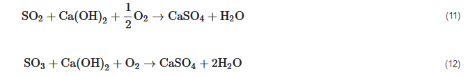
2.5. Dry Exhaust Gas Treatment and SOx Capture Systems

Dry exhaust gas treatment and SOx capture systems are used extensively in shore installations for the desulfurization of industrial flue gases. The operation of all dry exhaust gas cleaning systems is based on the use of limestone or hydrated lime to clean SOx from the flue gases. Even though the dry exhaust gas treatment process is a proven SOx reduction method, it has certain disadvantages such as the supply and the storage of lime products and the storage and the shore disposal of the used reactants. Dry exhaust gas treatment systems used for marine applications are based on a packing material bed from hydrated lime (calcium hydroxide). The maximization of the area of the dry exhaust gas cleaning system and the conservation for long time of the exhaust gases in contact with the packing material optimizes the removal of sulfur and particulate matter from the exhaust gas stream. The dry capture of sulfur oxides is based on the following chemical reactions [36]:
The previously mentioned reactions are exothermic, i.e., they release heat allowing the exhaust gas treatment system to thermally contribute to the efficiency of the exhaust gas boiler through proper installation. Dry exhaust gas cleaning systems do not reject impure substances to the maritime environment such as the aqueous exhaust gas treatment systems do. The used packing material is discharged to specific shore installations. According to one dry exhaust gas cleaning systems manufacturer, the residues of these units can be used in shore industrial installations for high temperature desulfurization based on the remaining capacity of the packing material for SOx capture. Dry exhaust gas cleaning systems have relatively lower energy consumption requirements compared to the conventional aqueous exhaust gas treatment systems (1.5–2 kW/MW of diesel engine power output). Therefore, the additional CO2 emissions from a vessel that operates with a dry exhaust gas treatment system are correspondingly low. However, the industrial process of production and distribution of packing material for dry exhaust gas treatment systems is anticipated to contribute to the total CO2 emissions, and this is a negative contribution of the dry exhaust gas cleaning systems [30].

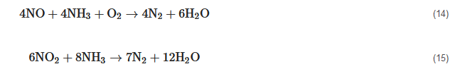
2.6. Marine Selective Catalytic Reduction (SCR) Systems

Marine diesel engine exhaust gases pass through a selective catalytic reduction reactor supplied with an aqueous solution of ammonia (urea). Nitrogen oxides are a mixture of nitric oxide (NO) and nitrogen dioxide (NO2). As the aqueous solution of ammonia is supplied to the exhaust gas stream, the water of the solution is vaporized. The high temperature of the exhaust gas stream results in the thermal decomposition of urea (NH2)2CO into ammonia (NH3) and carbon dioxide (CO2) based on the following chemical reaction [34,35]:
The chemical reactions that take place inside the selective catalytic reduction reactor are the following:
As can be concluded from the above two chemical reactions, the nitric oxide (NO) reacts with ammonia (NH3) and is converted to nitrogen (N2) and water (H2O), whereas the nitrogen dioxide (NO2) reacts with ammonia (NH3) and is converted to nitrogen (N2) and water (H2O). It is obvious that both nitrogen (N2) and water (H2O) are chemical species without negative repercussions on human health and the environment. The SCR reactor is manufactured from a ceramic monolith which operates as a chemical catalyst to facilitate the chemical reactions of NO and NO2 conversion to harmless N2 and H2O [34,35].
The marine diesel engine exhaust gases from the exhaust gas receiver are guided to the duct where the vaporization of the injected urea solution and its mixing with the exhaust gas stream is conducted. Afterwards, the gaseous mixture is supplied to the SCR system reactor, where the mixture of NO and NO2 is converted to N2 and H2O. As known, large two-stroke marine diesel engines are characterized by high brake efficiency and low trapping efficiency; so, the exhaust gas temperature exiting the turbocharger is relatively low and varies from 230 to 260 °C depending on engine load and ambient conditions. These low exhaust gas temperatures are problematic for the operation of the SCR system when heavy fuel oil (HFO), which contains high sulfur content, is used. Thus, with respect to the highest fuel flexibility, it has been a priority that marine diesel engines generate an exhaust gas stream with the proper temperature for the optimal operation of the SCR system. The inlet exhaust gas temperature to the SCR system should ideally vary from 330 to 350 °C when the marine diesel engine operates with HFO [34,35].

3. Applications of Marine Exhaust Gas Treatment Systems

3.1. Wet Closed-Loop and Open-Loop SOx Scrubbers

Many manufacturers of marine aqueous exhaust gas treatment systems have significant experience from similar shore applications (mainly as desulfurization units of flue gases that are generated from industrial installations and oil refineries). Other manufacturers of marine aqueous exhaust gas cleaning systems transfer their experience from the construction and installation of corresponding exhaust gas treatment and inert gas production systems for the maritime industry.
It should be clarified that starting in 2011 and after 20 years from the first testing installation, the aqueous exhaust gas scrubbers have shown considerable technological evolution. It should be noted that for more than 30 years the aqueous exhaust gas treatment systems have operated as exhaust gas treatment and inert gas production systems [36].
The first prototype aqueous exhaust gas treatment system with seawater was installed in a ship in 1991. Specifically, the installation was made in the passenger ferry Kronprins Harald of the Color Line Company [36]. In 1993, an aqueous exhaust gas treatment system with seawater was installed in the oil tanker MT Fjordshell. Another company processed a part of the exhaust gas stream of the icebreaker Louis S. St.-Laurent in 1998, and in cooperation with a large marine engine manufacturer installed a prototype exhaust gas treatment unit to mitigate mainly SOx emissions in the Ro/Pax Ferry Leif Ericson in 2001 [36]
In recent years, many manufacturers of aqueous exhaust gas processing systems have installed exhaust gas cleaning systems in ships. These installations include the systems installed in the Ro-Ro Ficaria Seaways, the Ro-Ro Pride of Kent, in the cruise ship Zaandam and in the chemical tankers Baru and Suula [36].
One SOx scrubber manufacturer has its own systems placed on a barge. Inside the harbor, the barge can come close to the ship in which the exhaust gas processing will take place, and the exhaust gas cleaning systems of the barge can capture unwanted gaseous emissions emitted from the diesel engines and exhaust gas boilers of the ship [29].
The main challenge that the on-board installation of a SOx scrubber must face concerns the purchasing and the transfer of the consumables (mainly caustic soda) that are required for the operation of the exhaust gas treatment systems. Caustic soda is consumed with a rate ranging between 1 and 15 L per hour and per MW of engine power. The higher the consumption of caustic soda is, the higher the SOx capture from exhaust gases in the scrubber [29].
The consumed quantity of caustic soda required for the achievement of specific SOx reductions in diesel engine gaseous emissions in comparison to those achieved by specific fuel sulfur content are the following:
  • Quantity of 11 L caustic soda with 50% w/w NaOH/MWh achieves SOx emissions equivalent to 2.9% sulfur in fuel oil.
  • Quantity of 8 L caustic soda with 50% w/w NaOH/MWh achieves SOx emissions equivalent to 2.4% sulfur in fuel oil.
  • Quantity of 4 L caustic soda with 50% w/w NaOH/MWh achieves SOx emissions equivalent to 1.4% sulfur in fuel oil.
  • Quantity of 1 L caustic soda with 50% w/w NaOH/MWh achieves SOx emissions equivalent to 0.9% sulfur in fuel oil.

3.2. Wet SOx and PM Scrubbers Integrated in Marine EGR Systems

One of the best known applications of a “dual” NOx and SOx mitigation system is the wet SOx and PM scrubber integrated in an EGR system installed in the containership Alexander Maersk. The on-board space requirements for the EGR installation are expected to be reduced as the experimental prototype installations are progressively converted to commercially available units. Preliminary estimations report that 15 to 20 m3 of on-board captured space are required for the EGR installation per 10 MW of diesel engine power [36].

3.3. Inert Gas Wet SOx Scrubbers

Inert gas scrubbers as parts of gas treatment systems are widely recognized as effective means of deactivating oil and chemical cargo, especially where higher grades of inert gases are not required (since the source is the flue gas boiler exhaust). Typical operational parameters in the case of inert gas scrubbers are the cooling requirements and the subsequent high seawater consumption demands which range from 0.010 to 0.020 m3/Nm3 of inert gas [36].

3.4. Dry SOx Scrubbers

In the present situation, only one manufacturer has commercially available dry exhaust gas cleaning and SOx mitigation systems for marine applications. This manufacturer has installed a testing dry SOx scrubber in the cargo ship MV Timbus which carried cellulose from Sweden to Holland [30]. The specific system was approved by class in April 2010. The dry SOx scrubber in the present phase of development has significant on-board space requirements. Both the dry exhaust gas processing unit and the storage facilities of the unprocessed and the processed packing material have considerable on-board space requirements [36]. The on-board space requirement for the packing material depends obviously on the operational profile of the ship and the availability of the unprocessed and processed packing material. A scrubber system manufacturer [59] guarantees the supply of new packing material when this is required and plans the construction of a packing material supply system in significant harbors around the world. Although the limestone is a directly available commercial product, its supply can set limitations to the number of ships in which its installation is suitable [30].

3.5. Marine Selective Catalytic Reduction (SCR) Systems

The selective catalytic reduction, which uses ammonia as reductive mean, was patented in the USA in 1957. From this year and on, thousands of SCR systems have been manufactured and installed in shore applications from industrial installations and electric power generation units to trains and cars. The maritime sector has more than two decades of technological experience with SCR systems. The first marine applications of SCR systems were conducted by large marine engine manufacturers [60]. Between 1989 and 1992, a well-known engine manufacturer tested the viability of SCR systems through their installation in four vessels in San Francisco Bay and received a certificate of acceptable operation of these system regarding their achieved NOx reduction from the corresponding maritime transport management body in the San Francisco Bay (Bay Area Air Quality Management District (BAAQMD). In addition, between 1999 and 2000, another large engine manufacturer installed SCR systems in three two-stroke main diesel engines of Ro-Ro vessels attaining NOx emissions of 2 g/kWh that were lower than Tier III values for 10 years of continuous operation. The use of SCR systems was expanded in 2000 and 2001 in LPG carriers. Today, SCR technology is widely accepted and is a highly effective NOx reduction technology with more than 500 examples of applications in the maritime sector until 2013 [60].
An important study was published in 2013 in which shipowners and operators gathered data for a significant number of vessels, engines, fuel types, and equipment manufacturers that they used to develop SCR technologies. Almost 1250 SCR systems have been installed in ships during the last decade. These ships have assembled more than 80,000 h of technological experience from the use of SCR systems during the last two decades. SCR technology has been implemented in different types of ships and marine engines with various types of fuels.
Although SCR technology was first installed in the exhaust of main marine diesel engines, SCR systems have been used for NOx mitigation in the exhaust of auxiliary engines and exhaust gas boilers. According to the study of IACCSEA [61], 67% of the ships that were examined in this study were equipped with SCR systems in their main marine engines, 23% of the examined ships had SCR systems installed in their auxiliary engines, and 9% of the examined ships used SCR systems for NOx mitigation in the flue gases generated from gas boilers [60,61]. In addition, SCR technology has successfully been operated in both engines and boilers with a variety of fuels, including low sulfur and high sulfur fuels. Almost half of the ships that were examined in the study of IACCSEA [61], used marine gas oil (MGO) or heavy fuel oil (HFO) almost at the same levels, whereas 22% of the examined cases in the specific study used light diesel oil, and 14% used marine diesel oil (MDO). In the specific study, a smaller number of engines operated with combinations of the previously mentioned fuels. According to the data of the study [61] and in combination with the conclusions of other studies [60], it is proven beyond doubt that SCR technology can be implemented in various types of ships with different fuel requirements which cannot be considered as limiting factors for the application of SCR technology. Many manufacturers have invested in SCR technology in the last 25 years from the first application of this technology to the maritime industry. A significant number of companies in Europe, the USA and Asia possess SCR technologies that are capable of satisfying current and future limits of NOx emissions from ships [60].
In SCR system applications, a variety of catalysts is used. The most suitable catalysts for marine applications appear to be vanadium catalysts due to their low cost and low sensitivity to the fuel sulfur content [49,50]. SCR catalysts should be replaced periodically to ensure the effective operation of SCR systems. SCR systems require intermediate inspections every 2.5 years and full inspections every 5 years. The used catalysts should be processed due to heavy metals that can be deposited after a period on the SCR catalysts. For this reason, one company has moved on to the regeneration of the used catalysts and to their reinstatement for commercial use. The effective lifetime of a marine SCR catalyst can be in the order of 5 to 6 years, whereas SCR catalyst manufacturers guarantee their continuous operation for almost 16,000 h [60]. For ships that operate for a small percentage of their lifetime inside NOx emission areas (NECAs), the lifetime of SCR catalysts can be extended, especially in the case of use of maritime fuel with 0.1% sulfur [50,60].
Today, there are various technologies for the extension of the marine diesel engine operational conditions to engine loads, where the SCR system operates effectively, under development. Marine diesel engine exhaust gas temperatures can be increased to be suitable for the exhaust gas processing from SCR systems under various techniques which include the reduction of intake air mass and the use of exhaust gas preheating before their entrance to the SCR unit. In addition, these techniques include the adjustment of fuel injection timing or the bypass of part of the generated exhaust gas mass flow rate through a heated hydrolysis catalyst which allows the urea injection at low exhaust gas temperatures of about 150 °C. They also include the heating of the urea quantity adjustment system before its injection into the exhaust gas stream for maximization of the effectiveness of the catalytic reduction system. For ships with more than one diesel engine, the interruption of the operation of one or more engines and the operation of a smaller number of engines at higher power output has been proposed. Under another strategy, at low engine loads, a part of the SCR catalyst can be bypassed through the condensation of the exhaust gas volume and its transportation into a smaller catalyst volume by sustaining at the same time the turbulent flow of the exhaust gases and the catalyst temperature. In 2011 a successful sea trial of a SCR system that managed to operate effectively for diesel engine operation at extremely low load (10% of full engine load) was completed [35,60].
In addition, the type of operation of the marine diesel engine (two-stroke or four-stroke) can allow the implementation of different control techniques of the SCR–engine system. Specifically, in four-stroke diesel engines, the SCR catalyst can be placed after the turbocharger. It has been observed that SCR systems coupled to four-stroke diesel engines can be operated efficiently at extremely low loads of 10% to 15% of full engine load. In two-stroke diesel engines, the catalyst is placed before the entrance of the exhaust gases to the turbine of the turbocharger, where the values of exhaust gas temperature and pressure are high. This technique has the advantage of allowing the SCR system to operate efficiently using a smaller reactor size. For two-stroke diesel engines, the placement of the SCR catalyst upstream of the turbocharger turbine can ensure the reduction of NOx emissions to 25% of the corresponding NOx emissions of the conventional diesel operation. In some cases, it can offer even higher NOx reductions. A SCR system placement technique before the turbocharger turbine has successfully been used for more than a decade in ships equipped with two-stroke diesel engines which required the control of NOx emissions when they operated at low engine loads close to the shore. In 2011, a diesel engine was approved, which used a small volume SCR system with high exhaust gas pressure and temperature and satisfied the IMO Tier III limits for NOx emissions for diesel engine operation at 10% of full engine load, whereas it generated extremely low CO2 emissions [60].
Overall, it can be stated that the requirement of urea supply of marine SCR systems is expected to be low compared to other applications of those systems. The application of SCR technology in vehicles is estimated to lead to a total urea consumption of 6 million tons. The existing maritime sector requires urea consumption less than 1% of all installed SCR systems at all applications. The Environmental Protection Agency (EPA) in the USA estimates that the total urea consumption in NOx emission areas in North America will be close to 454,000 tons in 2020, or it will be smaller than 10% of the total urea consumption in vehicle applications in 2015. Since SCR applications in vehicles are expected to consume no more than 5% of the global needs in urea production, this denotes that the total urea consumption for marine applications in 2020 will be significantly lower than 1% of the global needs [60].

This entry is adapted from the peer-reviewed paper 10.3390/en15103638

References

  1. Heywood, J.B. Internal Combustion Engine Fundamentals, 1st ed.; McGraw-Hill: New York, NY, USA, 1988.
  2. Dieselnet. IMO Marine Engine Regulations. 2020. Available online: https://dieselnet.com/standards/inter/imo.php (accessed on 2 April 2022).
  3. IMO. Sulfur Oxides (SOx) and Particulate Matter (PM)—Regulation 14. Available online: http://www.imo.org/en/OurWork/ Environment/PollutionPrevention/AirPollution/Pages/Sulfur-oxides-(SOx)-%E2%80%93-Regulation-14.aspx (accessed on 2 April 2022).
  4. European Commission. Report from the Commission to the European Parliament and the Council on Implementation and Compliance with the Sulfur Standards for Marine Fuels Set Out in Directive (EU) 2016/802 Relating to a Reduction in the Sulfur Content of Certain Liquid Fuels, Brussels. 16 April 2018. Available online: https://op.europa.eu/en/publication-detail/-/ publication/9050f35b-4155-11e8-b5fe-01aa75ed71a1/language-en/format-PDF (accessed on 2 April 2022).
  5. IMO. Nitrogen Oxides (NOx)—Regulation 13. Available online: http://www.imo.org/en/OurWork/Environment/ PollutionPrevention/AirPollution/Pages/Nitrogen-oxides-(NOx)-%E2%80%93-Regulation-13.aspx (accessed on 2 April 2022). 6. Deniz, C.; Zincir, B. Environmental and economical assessment of alternative marine fuels. J. Clean. Prod. 2016, 113, 438–449. [CrossRef]
  6. Notteboom, T.; Delhaye, E.; Vanherle, K. Analysis of the Consequences of Low Sulfur Fuel Requirements. University of Antwerpen Transport and Mobility. 2010. Available online: https://www.schonescheepvaart.nl/downloads/rapporten/doc_1361790123.pdf (accessed on 2 April 2022).
  7. Guo, M.; Fu, Z.; Ma, D.; Ji, N.; Song, C.; Liu, Q. A short review of treatment methods of marine diesel engine exhaust gases. Procedia Eng. 2015, 121, 938–943. [CrossRef]
  8. Lu, X.; Geng, P.; Chen, Y. NOx Emission reduction technology for marine engine based on Tier-III: A Review. J. Therm. Sci. 2020, 29, 1242–1268. [CrossRef]
  9. Lion, S.; Vlaskos, I.; Taccani, R. A review of emissions reduction technologies for low and medium speed marine Diesel engines and their potential for waste heat recovery. Energy Convers. Manag. 2020, 207, 112553. [CrossRef]
  10. Ni, P.; Wang, X.; Li, H. A review on regulations, current status, effects and reduction strategies of emissions for marine diesel engines. Fuel 2020, 279, 118477. [CrossRef]
  11. Deng, J.; Wang, X.; Wei, Z.; Wang, L.; Wang, C.; Chen, Z. A review of NOx and SOx emission reduction technologies for marine diesel engines and the potential evaluation of liquefied natural gas fuelled vessels. Sci. Total Environ. 2021, 766, 144319. [CrossRef]
  12. Ushakov, S.; Stenersen, D.; Einang, P.-M.; Ask, T.-O. Meeting future emission regulation at sea by combining low-pressure EGR and seawater scrubbing. J. Mar. Sci. Technol. 2020, 25, 482–497. [CrossRef]
  13. Hämäläinen, E. Estimated impacts of the sulfur directive on the Nordic industry. Eur. Transp. Res. Rev. 2015, 7, 8. [CrossRef]
  14. Lindstad, H.; Sandaas, I.; Strømman, A.H. Assessment of cost as a function of abatement options in maritime emission control areas. Transp. Res. Part D Transp. Environ. 2015, 38, 41–48. [CrossRef]
  15. Panasiuk, I.; Turkina, L. The evaluation of investments efficiency of SOx scrubber installation. Transp. Res. Part D Transp. Environ. 2015, 40, 87–96. [CrossRef]
  16. Hirata, K.; Niki, Y.; Kawada, M.; Iida, M. Development of Marine SCR System and Field Test on Ship. International Symposium on Marine Engineering (ISME) BEXCO, Busan, October 2009. Available online: https://www.nmri.go.jp/oldpages2/power-sys/ center/hirata/184_Koichi_Hirata.pdf (accessed on 2 April 2022).
  17. Magnusson, M.; Fridell, E.; Ingelsten, H.H. The influence of sulfur dioxide and water on the performance of a marine SCR catalyst. Appl. Catal. B Environ. 2012, 111, 20–26. [CrossRef]
  18. Cimino, S.; Lisi, L.; Tortorelli, M. Low temperature SCR on supported MnOx catalysts for marine exhaust gas cleaning: Effect of KCl poisoning. Chem. Eng. J. 2016, 283, 223–230. [CrossRef]
  19. Fridell, E.; Salo, K. Measurements of abatement of particles and exhaust gases in a marine gas scrubber. Proc. Inst. Mech. Eng. Part M J. Eng. Marit. Environ. 2016, 230, 154–162. [CrossRef]
  20. Brynolf, S.; Magnusson, M.; Fridell, E.; Andersson, K. Compliance possibilities for the future ECA regulations through the use of abatement technologies or change of fuels. Transp. Res. Part D Transp. Environ. 2014, 28, 6–18. [CrossRef]
  21. Ammar, N.R.; Seddiek, I.S. Eco-environmental analysis of ship emission control methods: Case study RO-RO cargo vessel. Ocean. Eng. 2017, 137, 166–173. [CrossRef]
  22. Seddiek, I.S.; Elgohary, M.M. Eco-friendly selection of ship emissions reduction strategies with emphasis on SOx and NOx emissions. Int. J. Nav. Archit. Ocean Eng. 2014, 6, 737–748. [CrossRef]
  23. Viana, M.; Hammingh, P.; Colette, A.; Querol, X.; Degraeuwe, B.; de Vlieger, I.; van Aardenne, J. Impact of maritime transport emissions on coastal air quality in Europe. Atmos. Environ. 2014, 90, 96–105. [CrossRef]
  24. Nikopoulou, Z. Incremental costs for reduction of air pollution from ships: A case study on North European emission control area. Marit. Policy Manag. 2017, 44, 1056–1077. [CrossRef]
  25. Boscarato, I.; Hickey, N.; Kašpar, J.; Prati, M.-V.; Mariani, A. Green shipping: Marine engine pollution abatement using a combined catalyst/seawater scrubber system. 1. Effect of catalyst. J. Catal. 2015, 328, 248–257. [CrossRef]
  26. Lindstad, H.; Eskeland, G.S.; Psaraftis, H.; Sandaas, I.; Strømman, A.H. Maritime shipping and emissions: A three-layered, damage-based approach. Ocean. Eng. 2015, 110, 94–101. [CrossRef]
  27. Dulebenets, M.A. Green vessel scheduling in liner shipping: Modeling carbon dioxide emission costs in sea and at ports of call. Int. J. Transp. Sci. Tech. 2018, 7, 26–44. [CrossRef]
  28. ABS. Exhaust Gas Scrubber Systems: Status and Guidance. 2013. Available online: https://ww2.eagle.org/content/dam/eagle/ publications/2013/Scrubber_Advisory.pdf (accessed on 2 April 2022).
  29. EGC Handbook 2012. A Practical Guide to Exhaust Gas Cleaning Systems for the Maritime Industry. 2012. Available online: https://www.egcsa.com/wp-content/uploads/EGCSA-Handbook-2012-A5-size-.pdf (accessed on 2 April 2022).
  30. Macdonald, F.; Rojon, I. (Eds.) Fathom Maritime Intelligence. Marine Scrubbers: The Guide 2015. 2015. Available online:
  31. http://www.fathommaritimeintelligence.com/uploads/2/5/3/9/25399626/scrubber_guide_sample_pages.pdf (accessed on 2 April 2022).
  32. Gregory, D.; West, M. EGCSA Handbook; Exhaust Gas Cleaning Systems Association: London, UK, 2010.
  33. Watanabe, Y.; Koyanagi, S. Development and installation of marine-use hybrid SOx scrubber system that complies with IMO SOx emission regulations. Mitsubishi Heavy Ind. Tech. Rev. 2016, 53, 48.
  34. MAN Diesel & Turbo. Tier III NOx Technologies—Comparison of EGR with SCR, Presentation; MAN Diesel & Turbo: Augsburg, Germany, 2013.
  35. MAN Diesel & Turbo. Marine Engine IMO Tier II and Tier III Programme 2015; Report. May 2022. Available online: https: //mandieselturbo.com/docs/default-source/sales-force-package/marine_engine_programme_2015.pdf?sfvrsn (accessed on 2 April 2022).
  36. Kjølholt, J.; Aakre, S.; Jürgensen, C.; Lauridsen, J. Assessment of Possible Impacts of Scrubber Water Discharges on the Marine Environment. Environmental Project No. 1431, Danish Ministry of Environment, Environmental Protection Agency. 2012. Available online: https://www2.mst.dk/Udgiv/publications/2012/06/978-87-92903-30-3.pdf (accessed on 2 April 2022).
  37. Krystallon, H. Sea Water Scrubbing—Does It Contribute to Increased Global CO2 Emission? Danish Ministry of the Environment:
  38. Littlehampton, UK, 2007.
  39. Hamworthy. Moss Flue Gas System, Inert Gas Systems; Hamworthy: Moss, Norway, 2007.
  40. Henriksson, T. SOx scrubbing of marine exhaust gases. Wartsila Tech. J. 2007, 55–58.
  41. Høy-Petersen, N. Answers to Specific Questions and General Information from Clean Marine, Oslo, Norway 2011. Available online: www.cleanmarine.com (accessed on 2 April 2022).
  42. Hufnagl, M.; Liebezeit, G.; Behrends, B. Effects of Sea Water Scrubbing; Final Report; BP Marine: Navi Mumbai, India, 2005.
  43. Kircher, D.; Stotz, T. Holland America Line Sea water scrubber demonstration project. In Proceedings of the Faster Freight, Cleaner Air Northwest Conference, Seattle, WA, USA, 17 September 2008.
  44. Kullas-Nyman, B.-M. Exhaust gas scrubbing systems: Technical and economic aspects. In Proceedings of the Wärtsilä Presentation, Maritime Stakeholder Event, Brussels, Belgium, 1 June 2011.
  45. Lloyd’s Register. Understanding Exhaust Gas Treatment Systems: Guidance for Shipowners and Operators. June 2012. Available online: https://www.rtu.lv/writable/public_files/RTU_understanding_exhaust_gas_treatment_systems.pdf (accessed on 2 April 2022).
  46. Oikawa, K.; Yongsiri, C.; Takeda, K.; Harimoto, T. Seawater flue gas desulfurization: Its technical implications and performance results. Environ. Prog. 2004, 22, 67–73. [CrossRef]
  47. Reynolds, K. Exhaust gas cleaning systems selection guide. In Ship Operations Cooperative Program; U.S. Department of Transportation: Elliot City, MD, USA, 2011.
  48. Ritchie, A.; de Jonge, E.; Hugi, C.; Cooper, D. Service Contract on Ship Emissions: Assignment, Abatement and Market-Based Instruments, Task 2c-SO2 Abatement; European Commission Directorate General Environment: Brussels, Belgium, 2005.
  49. Scala, F.; Lancia, A.; Nigro, R.; Volpicelli, G. Spray-dry desulfurization of flue gas from heavy oil combustion. J. Air Waste Manag. Assoc. 2005, 55, 20–29. [CrossRef]
  50. Wärtsilä. Wärtsilä Low-Speed Engines NOx—Emission—Tier III Solutions. INTERTANKO Annual Event, Technical Workshop—Air Emissions NOx Tier III; Wärtsilä: Athens, Greece, 2015.
  51. Wärtsilä. Wärtsilä Environmental Technologies, Wartsila Environmental Product Guide; Wärtsilä: Athens, Greece, 2015.
  52. Sun, X.; Meng, F.; Yang, F. Application of seawater to enhance SO2 removal from simulated flue gas through hollow fiber membrane contactor. J. Membr. Sci. 2008, 312, 6–14. [CrossRef]
  53. Tasin, A. Introduction to Scrubber Technologies; Wärtsilä Presentation: Newark, NJ, USA, 2015.
  54. Kouremenos, D.A.; Hountalas, D.T.; Binder, K.B.; Raab, A.; Schnabel, M.H. Using advanced injection timing and EGR to improve DI diesel engine efficiency at acceptable NO and soot levels. SAE Trans. 2001, 110, 55–68. [CrossRef]
  55. Ladommatos, N.; Abdelhalim, S.; Zhao, H.; Hu, Z. The dilution, chemical and thermal effects of exhaust gas recirculation on diesel emission—Part 1: Effect of reducing inlet charge oxygen. SAE Trans. 1996. [CrossRef]
  56. Ladommatos, N.; Abdelhalim, S.; Zhao, H.; Hu, Z. The dilution, chemical and thermal effects of exhaust gas recirculation on diesel emission—Part 2: Effects of carbon dioxide. SAE Trans. 1996. [CrossRef]
  57. Ladommatos, N.; Abdelhalim, S.; Zhao, H.; Hu, Z. The dilution, chemical and thermal effects of exhaust gas recirculation on diesel emission—Part 3: Effects of water vapour. SAE Trans. 1997. [CrossRef]
  58. Ladommatos, N.; Abdelhalim, S.; Zhao, H.; Hu, Z. The dilution, chemical and thermal effects of exhaust gas recirculation on diesel emission—Part 4: Effects of carbon dioxide and water vapour. SAE Trans. 1997, 106, 1844–1862. [CrossRef]
  59. Ladommatos, N.; Balian, R.; Horrocks, R.; Cooper, L. The effect of exhaust gas recirculation on soot formation in a high-speed direct-injection diesel engine. SAE Trans. 1996. [CrossRef]
  60. Couple Systems. The Very New Exhaust Gas Cleaning System; Couple Systems: Bardowick, Germany, 2010.
  61. Azzara, A.; Rutherford, D.; Wang, H. Feasibility of IMO Annex VI Tier III Implementation Using Selective Catalytic Reduction. The International Council on Clean Transportation (ICCT) 2014, Working Paper 2014-4. Available online: https://theicct.org/ sites/default/files/publications/ICCT_MarineSCR_Mar2014.pdf (accessed on 2 April 2022).
  62. International Association for Catalytic Control of Ship Emissions to Air (IACCSEA). 2020. Available online: https://www.
  63. iaccsea.com/wp-content/uploads/2018/12/IACCSEA-Marine-SCR-Technical-and-operational-capabilities-2013.pdf (accessed on 2 April 2022).
  64. Kang, X.; Ma, X.; Yin, J.; Gao, X. A study on simultaneous removal of NO and SO2 by using sodium persulfate aqueous scrubbing. Chin. J. Chem. Eng. 2018, 26, 1536–1544. [CrossRef]
  65. ABS, Global Sulfur Cap—2020. Available online: https://ww2.eagle.org/content/dam/eagle/advisories-and-debriefs/ABS_ Debrief_Global_Sulfur_Cap_16385.pdf (accessed on 2 April 2022).
  66. Caiazzo, G.; Langella, G.; Miccio, F.; Scala, F. An experimental investigation on seawater SO2 scrubbing for marine application. Environ. Progress Sustain. Energy 2013, 32, 1179–1186. [CrossRef]
  67. Chevron, Marine Lubricants White Paper, The 2020 Global Sulfur Cap and the Role of Cylinder Oil Lubricants. Available online: https://www.chevronmarineproducts.com/content/dam/chevron-marine/white-papers/2020%20Global%20Cap% 20Whitepaper%20DESKTOP.pdf (accessed on 2 April 2022).
  68. Ülpre, H.; Eames, I. Environmental policy constraints for acidic exhaust gas scrubber discharges from ships. Mar. Pollut. Bull. 2014, 88, 292–301. [CrossRef]
  69. Flagiello, D.; Erto, A.; Lancia, A.; Di Natale, F. Experimental and modelling analysis of seawater scrubbers for sulfur dioxide removal from flue-gas. Fuel 2018, 214, 254–263. [CrossRef]
  70. Abadie, L.-M.; Goicoechea, N.; Galarraga, I. Adapting the shipping sector to stricter emissions regulations: Fuel switching or installing a scrubber? Transp. Res. Part D Transp. Environ. 2017, 57, 237–250. [CrossRef]
  71. International Chamber of Shipping. Guidance to Shipping Companies and Crews on Preparing for Compliance with the 2020 ‘Global Sulfur Cap’ for Ships’ Fuel Oil in Accordance with MARPOL Annex VI, 1 July 2019. Available online: https://www.ics-shipping.org/docs/default-source/resources/guidance-for-compliance-with-the-2020-global-sulfur-capjuly-2019.pdf?sfvrsn=24 (accessed on 2 April 2022).
  72. Rass, K.; Affolter, S.; Mader, R.; Rozmyslowicz, B.; Stark, M.; Weber, M.F. Impact of Sulfur Cap 2020 on Two-Stroke Engine Tribology Aspects. 19th CIMAC Congress, Paper 437, Vancouver, Canada, 10–14 June 2019. Available online: https://www.wingd.com/ en/documents/general/papers/impact-of-sulfur-cap-2020-on-2-stroke-engine-tribology-cimac2019-paper-437-k-rass/ (accessed on 2 April 2022).
  73. Marocco, L. Modeling of the fluid dynamics and SO2 absorption in a gas–liquid reactor. Chem. Eng. J. 2010, 162, 217–226. [CrossRef]
  74. Brown, K.; Kalata, W.; Schick, R. Optimization of SO2 Scrubber using CFD Modeling. Procedia Eng. 2014, 83, 170–180. [CrossRef]
  75. Tang, X.-J.; Li, T.; Yu, H.; Zhu, Y.-M. Prediction model for desulfurization efficiency of on-board magnesium-base seawater scrubber. Ocean Eng. 2014, 76, 98–104. [CrossRef]
  76. Kim, A.-R.; Seo, Y.-J. The reduction of SOx emissions in the shipping industry: The case of Korean companies. Mar. Policy 2019, 100, 98–106. [CrossRef]
  77. Gu, Y.; Wallace, S.W. Scrubber: A potentially overestimated compliance method for the Emission Control Areas. The importance of involving a ship’s sailing pattern in the evaluation. Transp. Res. Part D Transp. Environ. 2017, 55, 51–66. [CrossRef]
  78. Makkonen, T.; Inkinen, T. Sectoral and technological systems of environmental innovation: The case of marine scrubber systems. J. Clean. Prod. 2018, 200, 110–121. [CrossRef]
  79. Schinas, O.; Stefanakos, C.N. Selecting technologies towards compliance with MARPOL Annex VI: The perspective of operators. Transp. Res. Part D Transp. Environ. 2014, 28, 28–40. [CrossRef]
  80. Darake, S.; Hatamipour, M.S.; Rahimi, A.; Hamzeloui, P. SO2 removal by seawater in a spray tower: Experimental study and mathematical modeling. Chem. Eng. Res. Des. 2016, 109, 180–189. [CrossRef]
  81. Jiang, L.; Kronbak, J.; Christensen, L.-P. The costs and benefits of sulfur reduction measures: Sulfur scrubbers versus marine gas oil. Transp. Res. Part D Transp. Environ. 2014, 28, 19–27. [CrossRef]
  82. Lindstad, H.E.; Rehn, C.-F.; Eskeland, G.S. Sulfur abatement globally in maritime shipping. Transp. Res. Part D Transp. Environ. 2017, 57, 303–313. [CrossRef]
  83. Endres, S.; Maes, F.; Hopkins, F.; Houghton, K.; Mårtensson, E.M.; Oeffner, J.; Quack, B.; Singh, P.; Turner, D. A new perspective at the ship-air-sea-interface: The environmental impacts of exhaust gas scrubber discharge. Front. Mar. Sci. 2018, 5, 139. [CrossRef]
  84. Turkina, L.; Panasiuk, I. Optimization of production of ship hull parts. In Proceedings of the 15th International Conference Transport Means 2011, Kaunas, Lithuania, 20–21 October 2011.
  85. Turner, D.R.; Edman, M.; Gallego-Urrea, J.-A.; Claremar, B.; Hassellov, I.-M.; Omstedt, A.; Rutgersson, A. The potential future contribution of shipping to acidification of the Baltic Sea. Ambio 2018, 47, 368–378. [CrossRef]
  86. Ma, H.; Steernberg, K.; Riera-Palou, X.; Tait, N. Well-to-wake energy and greenhouse gas analysis of SOx abatement options for the marine industry. Transp. Res. Part D Transp. Environ. 2012, 17, 301–308. [CrossRef]
  87. Kackur, J. Wartsila, Shipping in the 2020 Era—Selection of Fuel and Propulsion Machinery, Business White Paper. Available online: https://www.motorship.com/__data/assets/pdf_file/0036/986319/White-Paper_Shipping-in-the-2020-era_Pre-final. pdf (accessed on 2 April 2022).
  88. An, S.; Nishida, O. New application of seawater and electrolyzed seawater in air pollution control of marine diesel engine. JSME Int. J. Ser. B Fluids Therm. Eng. 2003, 46, 206–213. [CrossRef]
  89. Andreasen, A.; Mayer, S. Use of seawater scrubbing for SO2 removal from marine engine exhaust gas. Energy Fuels 2007, 21, 3274–3279. [CrossRef]
  90. Caiazzo, G.; Di Nardo, A.; Langella, G.; Scala, F. Seawater scrubbing desulfurization: A model for SO2 absorption in fall-down droplets. Environ. Prog. Sustain. Energy 2012, 31, 277–287. [CrossRef]
  91. Caiazzo, G.; Miccio, F.; Scala, F. Modeling Heat and Mass Transfer in a Seawater Scrubber for Marine Application: Some Improvements Based on a CFD Simulation. XXXVI Meeting of the Italian Section of the Combustion Institute. 2013. Available online: http://www.combustion-institute.it/proceedings/XXXVI-ASICI/papers/36proci2013.VI1.pdf (accessed on 2 April 2022). 90. Rakopoulos, C.D.; Giakoumis, E.G.; Hountalas, D.T.; Rakopoulos, D.C. The Effect of Various Dynamic, Thermodynamic and Design Parameters on the Performance of a Turbocharged Diesel Engine Operating under Transient Load Conditions; SAE Technical Paper 2004-01-0926; SAE International: New York, NY, USA, 2004. [CrossRef]
  92. Kosmadakis, G.M.; Rakopoulos, D.C.; Rakopoulos, C.D. Methane/hydrogen fueling a spark-ignition engine for studying NO, CO and HC emissions with a research CFD code. Fuel 2016, 185, 903–915. [CrossRef]
  93. Rakopoulos, D.C.; Rakopoulos, C.D.; Giakoumis, E.G.; Kosmadakis, G.M. Numerical and experimental study by quasidimensional modeling of combustion and emissions in variable compression ratio high-speed spark-ignition engine. ASCE J. Energy Eng. 2021, 147, 04021032. [CrossRef]
  94. Papagiannakis, R.G.; Hountalas, D.T.; Rakopoulos, C.D.; Rakopoulos, D.C. Combustion and Performance characteristics of a Di Diesel Engine Operating from Low to High Natural Gas Supplement Ratios at Various Operating Conditions; SAE Technical Paper No.
  95. 2008-01-1392; SAE International: New York, NY, USA, 2008. [CrossRef]
  96. Papagiannakis, R.G.; Krishnan, S.R.; Rakopoulos, D.C.; Srinivasan, K.K.; Rakopoulos, C.D. A combined experimental and theoretical study of diesel fuel injection timing and gaseous fuel/diesel mass ratio effects on the performance and emissions of natural gas–diesel HDDI engine operating at various loads. Fuel 2017, 202, 675–687. [CrossRef]
  97. Rakopoulos, D.C.; Rakopoulos, C.D.; Giakoumis, E.G.; Papagiannakis, R.G. Evaluating oxygenated fuel’s influence on combustion and emissions in diesel engines using a two-zone combustion model. ASCE J. Energy Eng. 2018, 144, 04018046. [CrossRef]
  98. Rakopoulos, C.D.; Rakopoulos, D.C.; Kosmadakis, G.M.; Papagiannakis, R.G. Experimental comparative assessment of butanol or ethanol diesel-fuel extenders impact on combustion features, cyclic irregularity, and regulated emissions balance in heavy-duty diesel engine. Energy 2019, 174, 1145–1157. [CrossRef]
  99. Rakopoulos, C.D.; Rakopoulos, D.C.; Mavropoulos, G.C.; Kosmadakis, G.M. Investigating the EGR rate and temperature impact on diesel engine combustion and emissions under various injection timings and loads by comprehensive two-zone modeling. Energy 2018, 157, 990–1014. [CrossRef]
  100. Rakopoulos, D.C. Effects of exhaust gas recirculation under fueling rate or air/fuel ratio–controlled strategies on diesel engine performance and emissions by two-zone combustion modeling. ASCE J. Energy Eng. 2021, 147, 04020079. [CrossRef]
  101. Rakopoulos, D.C.; Rakopoulos, C.D.; Kosmadakis, G.M.; Giakoumis, E.G. Exergy assessment of combustion and EGR and load effects in DI diesel engine using comprehensive two-zone modeling. Energy 2020, 202, 117685. [CrossRef]
  102. Rakopoulos, C.D.; Giakoumis, E.G. Development of cumulative and availability rate balances in a multi-cylinder turbocharged indirect injection diesel engine. Energy Convers. Manag. 1997, 38, 347–369. [CrossRef]
  103. Giakoumis, E.G.; Rakopoulos, D.C.; Rakopoulos, C.D. Combustion noise radiation during dynamic diesel engine operation including effects of various biofuels blends: A review. Renew. Sust. Energy Rev. 2016, 54, 1099–1113. [CrossRef]
  104. Rakopoulos, C.D.; Mavropoulos, G.C. Experimental instantaneous heat fluxes in the cylinder head and exhaust manifold of an air-cooled diesel engine. Energy Convers. Manag. 2000, 41, 1265–1281. [CrossRef]
  105. Rakopoulos, C.D.; Rakopoulos, D.C.; Kyritsis, D.C.; Andritsakis, E.C.; Mavropoulos, G.C. Exergy evaluation of equivalence ratio, compression ratio and residual gas effects in variable compression ratio spark-ignition engine using quasi-dimensional combustion modelling. Energy 2022, 244, 123080. [CrossRef]
  106. Tingas, E.A.; Im, H.G.; Kyritsis, D.C.; Goussis, D.A. The use of CO2 as an additive for ignition delay and pollutant control in CH4/Air autoignition. Fuel 2018, 211, 898–905. [CrossRef]
  107. Tingas, E.-A.; Kyritsis, D.C.; Goussis, D.A. H2/Air autoignition dynamics around the third explosion limit. ASCE J. Energy Eng. 2019, 145, 04018139. [CrossRef]
  108. Konstandopoulos, A.G.; Zarvalis, D.; Chasapidis, L.; Deloglou, D.; Vlachos, N.; Kotrba, A.; Anderson, G. Investigation of SCR catalysts for marine diesel applications. SAE Int. J. Engines 2017, 10, 1653–1666. [CrossRef]
  109. Liang, X.; Xiao, J.; Xu, Y.; Liu, S.; Men, X. CFD simulations to research the control rules with gate leaves in SCR-DeNOx facility for marine diesel engines. In Proceedings of the 2015 34th Chinese Control Conference (CCC), Hangzhou, China, 28–30 July 2015.
  110. Chen, Y.; Lv, L. Design and evaluation of an integrated SCR and exhaust muffler from marine diesels. J. Mar. Sci. Technol. 2015, 20, 505–519. [CrossRef]
  111. Zhu, Y.; Xia, C.; Shreka, M.; Wang, Z.; Yuan, L.; Zhou, S.; Feng, Y.; Hou, Q.; Abdu Ahmed, S. Combustion and emission characteristics for a marine low-speed diesel engine with high-pressure SCR system. Environ. Sci. Pollut. Res. 2020, 27. [CrossRef]
  112. Park, T.; Sung, Y.; Kim, T.; Lee, I.; Choi, G.; Kim, D. Effect of static mixer geometry on flow mixing and pressure drop in marine SCR applications. Int. J. Nav. Archit. Ocean Eng. 2014, 6, 27–38. [CrossRef]
  113. Guo, Y.; Deng, Y.; Zhang, J.; Shen, Y.; Wilson, C. Experimental and numerical analysis of NOx reduction in marine urea-SCR system. In Proceedings of the 4th International Conference on Information, Cybernetics and Computational Social Systems (ICCSS), Dalian, China, 24–26 July 2017; pp. 450–455.
  114. Ayre, L.S.; Johnson, D.R.; Clark, N.N.; England, J.A.; Atkinson, R.J.; McKain, D.L., Jr.; Ralston, B.A.; Thomas, H.; Balon, T.H., Jr.; Moynihan, P.J. Novel NOx emission reduction technology for diesel marine engines. In Proceedings of the ASME 2011 Internal Combustion Engine Division Fall Technical Conference, ICEF2011, Morgantown, WV, USA, 2–5 October 2011. ICEF2011-60182.
  115. Xiao, Y.; Zhao, H.; Tian, X.; Tan, W. Investigation on the control strategy for marine selective catalytic reduction system. ASME Trans. J. Dyn. Sys. Meas. Control 2019, 141, 011005. [CrossRef]
  116. Foteinos, M.I.; Konstantinidis, S.K.; Kyrtatos, N.P.; Busk, K.-V. Simulation of the transient thermal response of a high pressure selective catalytic reduction aftertreatment system for a Tier III two-stroke marine diesel engine. ASME Trans. J. Eng. Gas Turbines Power 2019, 141, 071001. [CrossRef]
  117. Xi, H.; Zhou, S.; Zhou, J. New experimental results of NO removal from simulated marine engine exhaust gases by Na2S2O8/urea solutions. Chem. Eng. J. 2019, 362, 12–20. [CrossRef]
  118. Choi, C.; Sung, Y.; Choi, G.-M.; Kim, D.-J. Numerical analysis of NOx reduction for compact design in marine urea-SCR system. Int. J. Nav. Archit. Ocean Eng. 2015, 7, 1020–1033. [CrossRef]
  119. Zhu, Y.; Zhang, R.; Zhou, S.; Huang, C.; Feng, Y.; Shreka, M.; Zhang, C. Performance optimization of high-pressure SCR system in a marine diesel engine. Part I: Flow optimization and analysis. Top. Catal. 2019, 62, 27–39. [CrossRef]
  120. Zhu, Y.; Zhang, R.; Zhou, S.; Huang, C.; Feng, Y.; Shreka, M.; Zhang, C. Performance optimization of high-pressure SCR system in a marine diesel. Part II: Catalytic reduction and process. Top. Catal. 2019, 62, 40–48. [CrossRef]
  121. Kleinhenz, M.; Fiedler, A.; Lauer, P.; Döring, A. SCR coated DPF for marine engine applications. Top. Catal. 2019, 62, 282–287.
  122. [CrossRef]
  123. Ha, T.-H.; Nishida, O.; Fujita, H.; Wataru, H. Simultaneous removal of NOx and fine diesel particulate matter (DPM) by electrostatic water spraying scrubber. J. Mar. Eng. Technol. 2014, 8, 45–53. [CrossRef]
  124. Zis, T.; Psaraftis, H.N. Operational measures to mitigate and reverse the potential modal shifts due to environmental legislation. Marit. Policy Manag. 2019, 46, 117–132. [CrossRef]
  125. Lehtoranta, K.; Aakko-Saksa, P.; Murtonen, T.; Vesala, H.; Ntziachristos, L.; Rönkko, T.; Karjalainen, P.; Kuittinen, N.; Timonen, H. Particulate mass and nonvolatile particle number emissions from marine engines using low-sulfur fuels, natural gas, or scrubbers. Environ. Sci. Technol. 2019, 53, 3315–3322. [CrossRef] [PubMed] 123. Greek Shipowner. Personal communication, 2020.
  126. DNV GL. Global Sulfur Cap 2020, Compliance Options and Implications for Shipping—Focus on Scrubbers. Available online: https://www.dnvgl.com/maritime/publications/global-sulfur-cap-2020.html (accessed on 2 April 2022).
  127. Yang, Z.L.; Zhang, D.; Caglayan, O.; Jenkinson, I.D.; Bonsall, S.; Wang, J.; Huang, M.; Yan, X.P. Selection of techniques for reducing shipping NOx and SOx emissions. Transp. Res. Part D Transp. Environ. 2012, 17, 478–486. [CrossRef]
  128. Claremar, B.; Haglund, K.; Rutgersson, A. Ship emissions and the use of current air cleaning technology: Contributions to air pollution and acidification in the Baltic Sea. Earth Syst. Dyn. 2017, 8, 901–919. [CrossRef]
  129. Bouman, E.A.; Lindstad, E.; Rialland, A.I.; Strømman, A.H. State-of-the-art technologies, measures, and potential for reducing GHG emissions from shipping—A review. Transp. Res. Part D Transp. Environ. 2017, 52, 408–421. [CrossRef]
  130. Williams, P.J. Use of seawater as makeup water for wet flue gas desulfurization systems. In Proceedings of the EPRI-DOE-EPA Combined Utility Air Pollutant Control Symposium, Atlanta, GA, USA, 16–20 August 1999.
  131. International Maritime Organization. Investigation of Appropriate Control Measures (Abatement Technologies) to Reduce Black Carbon Emissions from International Shipping 2015. Available online: http://www.imo.org/en/OurWork/Environment/ PollutionPrevention/AirPollution/Documents/Air%20pollution/Black%20Carbon.pdf (accessed on 2 April 2022).
  132. DNV GL. Global Sulfur Cap 2020. Get Insights on Compliance Options and Implications for Shipping. Focus on Scrubbers; DNV GL: Bærum, Norway, 2019.
  133. DNV GL. Global Sulfur Cap 2020. Know the Different Choices and Challenges for On-Time Compliance; DNV GL: Bærum, Norway, 2020. 132. The Swedish Club, Sulfur Guide, Dealing with the Sulfur Cap 2020 and Beyond. Available online: https://www.swedishclub. com/media_upload/files/Publications/Loss%20Prevention/Sulfur-Guide%202019%20www.pdf (accessed on 2 April 2022).
  134. Cho, B.K.; Lee, J.H.; Crellin, C.C.; Olson, K.L.; Hilden, D.L.; Kim, M.K.; Kim, P.S.; Heo, I.; Oh, S.H.; Nam, I.-S. Selective catalytic reduction of NOx by diesel fuel: Plasma-assisted HC/SCR system. Catal. Today 2012, 191, 20–24. [CrossRef]
  135. Liu, B.; Wu, X.; Liu, X.; Gong, M. Assessment of ecological stress caused by maritime vessels based on a comprehensive model using AIS data: Case study of the Bohai Sea, China. Ecol. Indic. 2021, 126, 107592. [CrossRef]
  136. Zhang, Y.; Yang, X.; Brown, R.; Yang, L.; Morawska, L.; Ristovski, Z.; Fu, Q.; Huang, C. Shipping emissions and their impacts on air quality in China. Sci. Total Environ. 2017, 581–582, 186–198. [CrossRef]
More
This entry is offline, you can click here to edit this entry!