- 3-D dimension, Osteotomy, Canine
1. Content
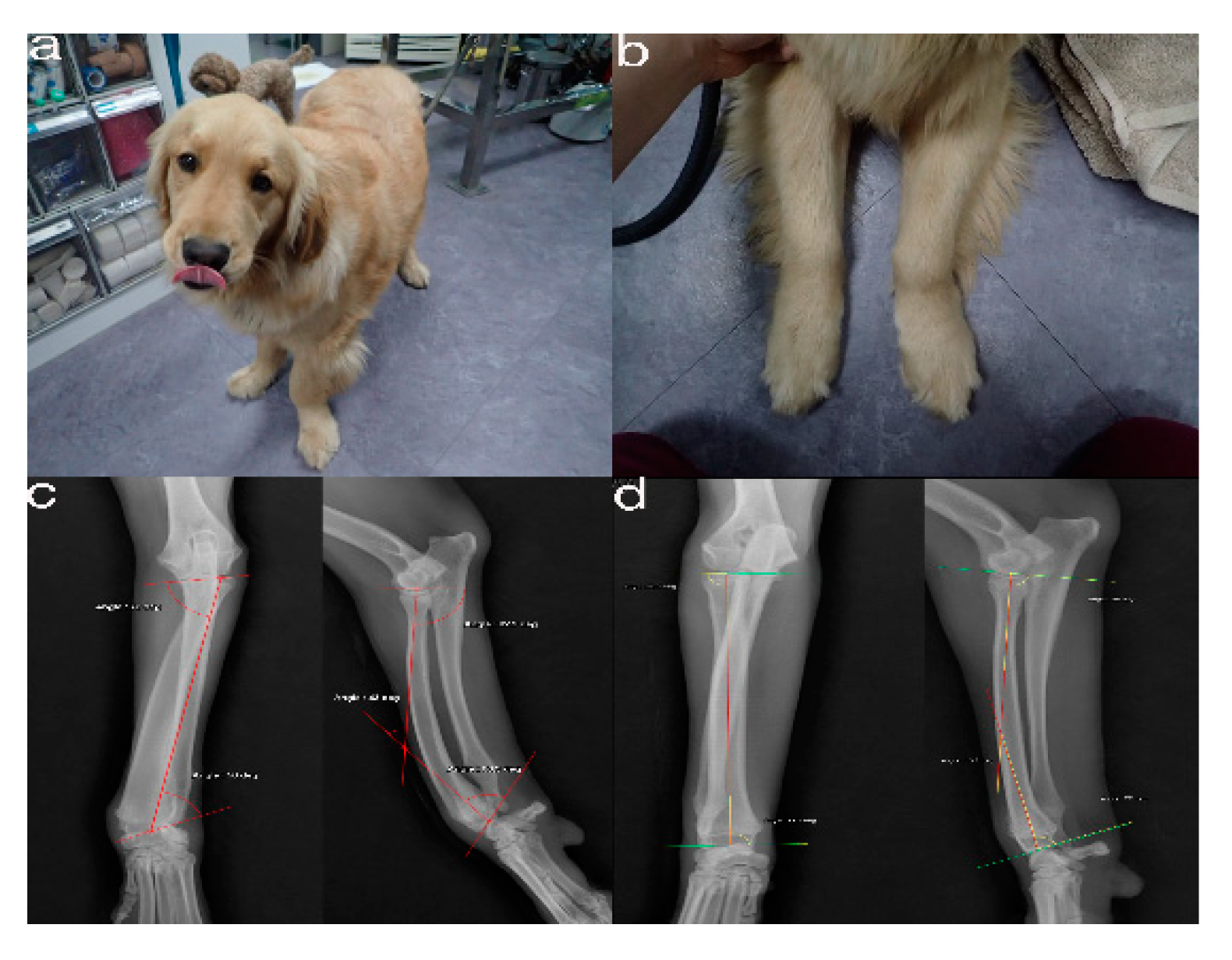
Figure 1. The images show the antebrachial growth deformity (AGD)-affected (left leg) and contralateral unaffected-antebrachium (right leg) with the joint-orientation angles (a,b), and orthogonal radiographs (c,d).
Pr of
Figure 2. CT from the distal third of the humerus to the metacarpal bones of both the affected (a) and unaffected leg (b).
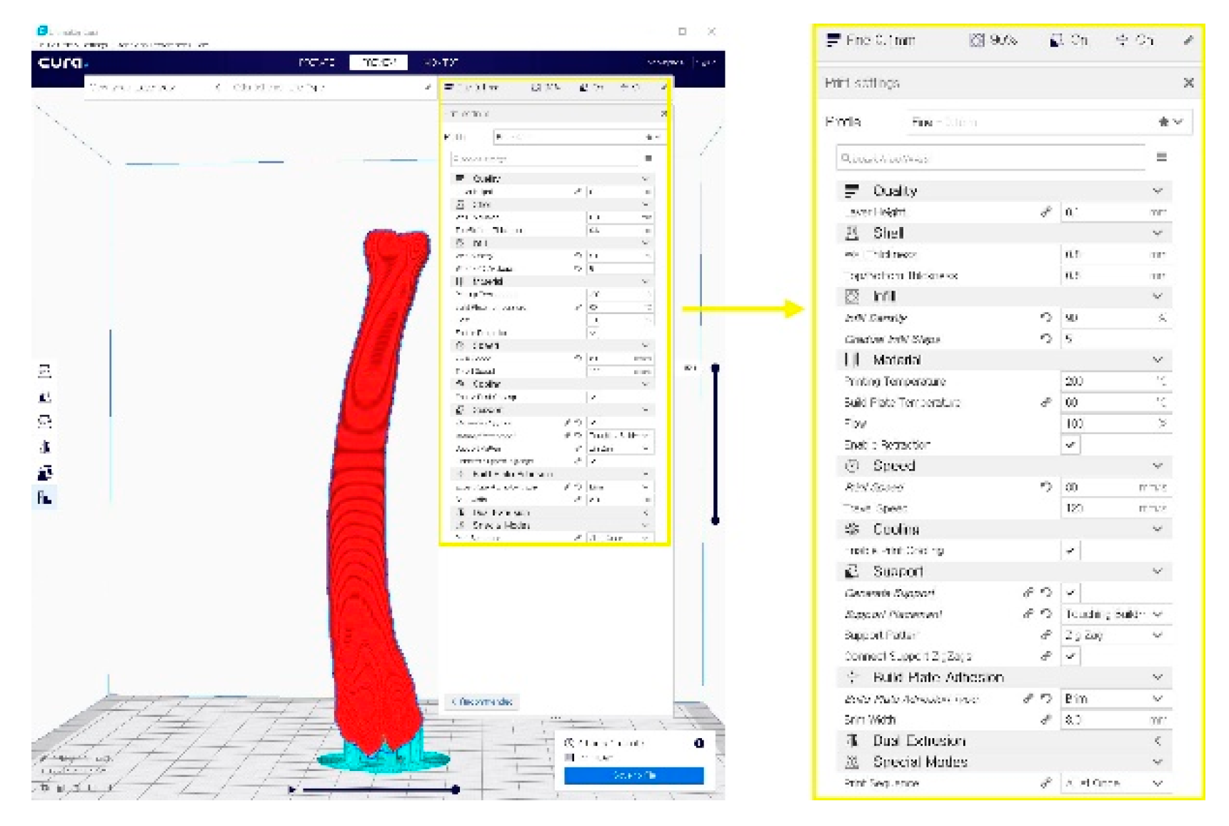
Figure 4. A G-code file generating process for the 3-D printing process. It can be generated from the STL image using the CURA application program.
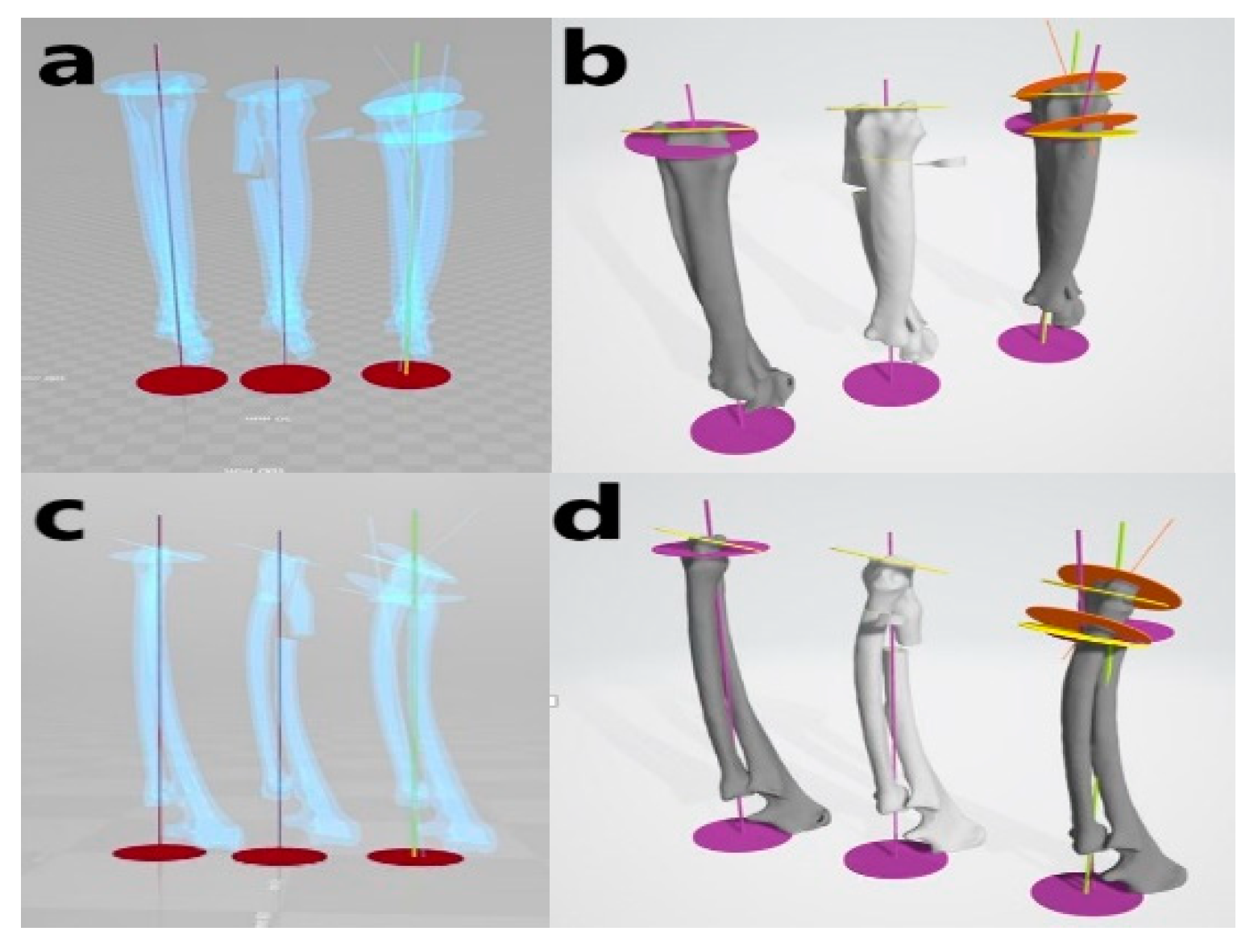
Figure 5. Virtual simulative corrective osteotomy. Surgical simulations were performed in virtual reality to predict postoperative conditions. Note the change in the axis before and after the virtual corrective osteotomy. The figure on the left (a,c) shows penetrated images and on the right (b,d) are 3-D rendering images.
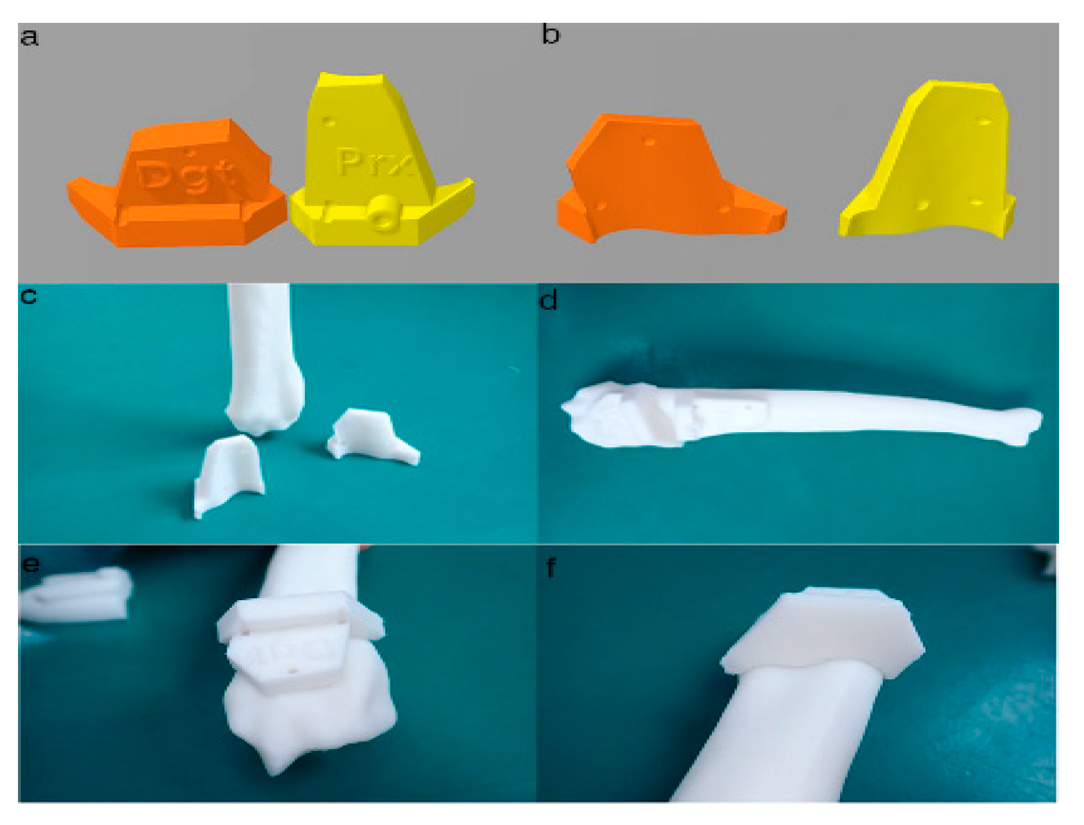
Figure 6. Final designs of patient-specific instrumentation (PSI) models were demonstrated through 3-D rendering images (a,b), 3-D printed PSIs (c), and the PSIs positioning on a rapid prototyping (RP) bone model precisely (d–f). The patient-specific cutting guides added a drill guide for the bone plate and screw placement. The PSIs attached on the RP bone model in-situ (d–f).

Figure 7. Rapid prototyping bone models were fabricated with the polylactic acid material using the fused deposition modeling method (above, a,b) and then the phantom bone models were fabricated for this study (below, c).
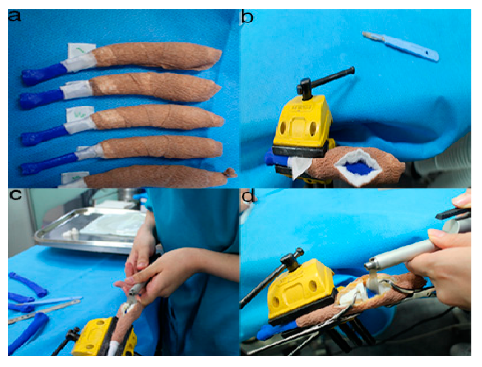
Figure 8. The position and angles for the cutting procedures. Prior to the ex-vivo osteotomy, each of the five operators were directed to position the phantom bone model to a vise (a,b). The surgical planning conditions for the freehand method were the same as the patient-specific instrumentation (PSI) method (c). Positioning PSI was ordered without positioning aids, but was only fixed on the rapid prototyping model using the bone-holding forceps or K-wires for temporary fixation (d).
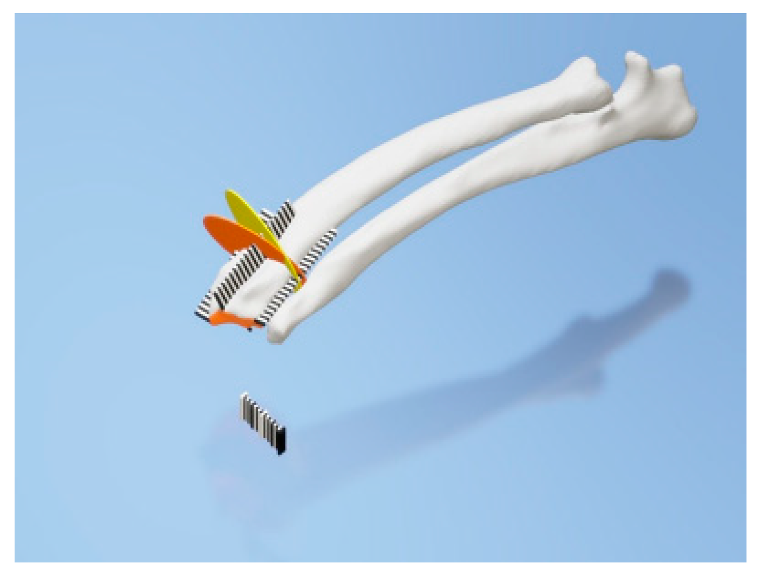
Figure 9. Rulers were attached to the cranial, caudal, medial, and lateral bone model surfaces. The orange and yellow plates show the osteotomy target plane. The black and white striped bar is made 1 mm against each space to indicate the distance from the edge of the joint surface.
This entry is adapted from the peer-reviewed paper 10.3390/ani10091445