Your browser does not fully support modern features. Please upgrade for a smoother experience.
Please note this is an old version of this entry, which may differ significantly from the current revision.
Decarbonization in the shipping industry could be achieved through technical and operational strategies such as Energy Saving Devices (ESDs) to reduce the fuel consumption of new and existing ships. According to the makers, ESDs can optimize fuel efficiency by up to 15%. This paper reviews the current literature on stern hydrodynamic ESDs, which are mainly used on typical merchant vessels, i.e., bulkers, tankers, and carriers.
- energy saving device (ESD)
- wake equalizing duct
- ship
- shipping decarbonisation
- hydrodynamics
1. Introduction
Regarding new ship-building, since 2013, there has been in force the Energy Efficiency Design Index (EEDI) defined by the Marine Environment Protection Committee (MEPC), an IMO committee, that prescribes a reduction of exhaust GHG for all vessels over 400 gross tonnes (GT) [1]. This is a measure that helps the industry, during the design phase, to decide which technologies should be installed on a specific ship. However, as every vessel is characterized by having a long lifespan (up to thirty years), the replacement of engines will only happen in the long run. As ship-owners are interested in minimizing the downtime of their vessels, fitting highly efficient propellers and rudders and/or equipping them with stationary flow-directing devices, generally called Energy Saving Devices (ESDs), can represent one of the most cost-effective solutions to meet the regulations and improve the ship efficiency.
These regulations do not apply only to new ship-building; recently (June 2021), there has been issued by MEPC the new ship energy efficiency index, i.e., Energy Efficiency Existing Ships Index (EEXI) [2], which covers all the existing vessels above 400 GT. In more detail, ships whose current attained EEXI does not comply with the reference value shall undergo any measure to improve their efficiency. On average, bulk carriers, tankers and container ships notably operate between 11 knots and 14 knots, or between 38% to 50% of their Maximum Continuous Rating (MCR). This is well below the engine loads that would be allowable under the EEXI, which range from 65% to 77% MCR [3]. In this operative rating, the Specific Fuel Consumption of Diesel Engine is far from its optimum; as a consequence, the fuel consumption and emission are very high.
To efficiently reduce ship speed or CO2, thus giving a heavy impact, the EEXI should be able to codify current operational efficiency gains due to slow steaming, rather than further reducing ship speed [4]. Introducing an EPL (Engine Power Limitation) can easily limit the maximum engine power to an optimal range, without any invasive intervention. Another option to comply with the EEXI requirement is to apply ESD, obtaining an increase in the reference speed (Vref) at the same power level, where Vref is the reference speed estimated at reference engine power (generally 75% of MCR) and a certain draught of the vessel (scantling draught) [2]. The advantages of the implementation of ESD on the attained EEXI value are mainly related to the compliance of the IMO rules without applying EPL or even reducing the EPL applied on the main engine with undebatable commercial advantages for the “charter-ability” of the vessels.
In general, with the expression ESDs, a broad spectrum of devices can be included, but the purpose of the present analysis is to investigate the typical hydrodynamic ESDs applied on commercial vessels. These ESDs are mainly focused on reducing the amount of propeller energy losses in the water flow i.e., rotational, or axial losses. The consequence is an equal amount of thrust for the lower engine power, thus yielding lower fuel consumption, and consequently lowering the carbon dioxide emissions. Various types of ESDs have been developed since the energy crisis in the late 1970s and can be applied to existing vessels by means of refitting or can be applied from the early design stages of new vessels.
The ESD, which may also be referred to as stationary flow directing devices, are usually located near the propeller. They vary in position and may be located behind the propeller, on the propeller, or on the rudder. The objective of designing these devices is to improve losses in the ship’s wake and rotational losses in the slipstream. These goals can be achieved by the duct and fins. The history of ESD is explained in more detail in the text.
2. Typical ESD Features
The ESDs can be divided by three locations of installation, according to the energy-saving device’s working principle, or to what energy losses they try to minimize. These can be positioned either ahead of the propeller fixed to the ship’s hull, or behind, fixed either to the rudder or the propeller itself. Some devices have conflicting operational functions, but these three categories are very useful to broadly group the various devices. In the present paper, devices located astern of the propeller are principally considered. These devices operate in the final stages of the growth of the hull’s boundary layer [5].
As declared by Schuiling [6], the form of each ESD should be defined only by clarifying its specific design function, i.e., its working principle and what it must do to reduce the power demand.
2.1. Pre-Swirl Stator (PSS)
The CFD analyses have shown that a set of fins astern the propeller generates a pre-swirl which positively affects the propeller efficiency. The PSS consists of blades mounted on the stern boss in front of the propeller so that the flow is redirected before entering the propeller disc.
It does not save energy on its own nor create a forward thrust; for really it increases the resistance, but its interaction with the propeller blade improves the propulsive efficiency and results in a power reduction.
Joint research by HSVA, MARIN, Wartsila, Bureau Veritas, Vicus DT, and IMAWIS [7], validated the numerical results of a bulk carrier sailing at 16 knots with and without a PSS device and found a good performance improvement.
Research works to validate the real effect of energy-saving devices are carried out as a form of Joint Industrial Project (JIP). For example, LeanShips by MARIN and Wärtsilä was the context for testing a pre-swirl stator combined with a controllable pitch propeller (CPP) on a single-screw ship [8].
Furthermore, Dang et al. [9] worked on a pre-duct with a stator, whose combination of accelerating effect (by the duct) and the swirl (by the stator) contributes to increasing the kinetic energy of the nominal wake field. In some conditions, instead of the assumed pre-swirl function, the stator in the duct may convert some rotational energy of the ship wake flow into net thrust (acting as a post-stator) [9].
Recently, Nadery et al. [10] highlighted that the application of PSS can increase the thrust and torque propeller coefficients.
2.2. Pre-Swirl Duct (PSD)
One of the most widespread circular ducts is marketed by Becker Marine Systems GmbH & Co. (Hamburg, Germany) under the trademark Mewis duct® and consists of a wake equalizing duct combined with an integrated pre-swirl fin system, thus reflecting two operating conditions:
-
The first pre-duct principle, published by Van Lammeren in 1949 [11], promoted a duct ahead of the propeller, whose axis is above the shaft so that it guarantees a more equalized propeller inflow;
Figure 2 shows the evolution of the upstream ducted ESDs. The first commercial one is the Mitsui Integrated Duct Propeller (MDIP) by Mitsui Engineering & Shipbuilding (Tokyo, Japan) which is an annular steel nozzle, located immediately in front of the propeller and is slightly non-axisymmetric. Almost simultaneously, the Hitachi Zosen Nozzle (HZN) by Hitachi Zosen Corporation (Osaka, Japan) was developed. Its design is almost equal to the MIDP, except for a larger deviation from the axisymmetric condition [13].
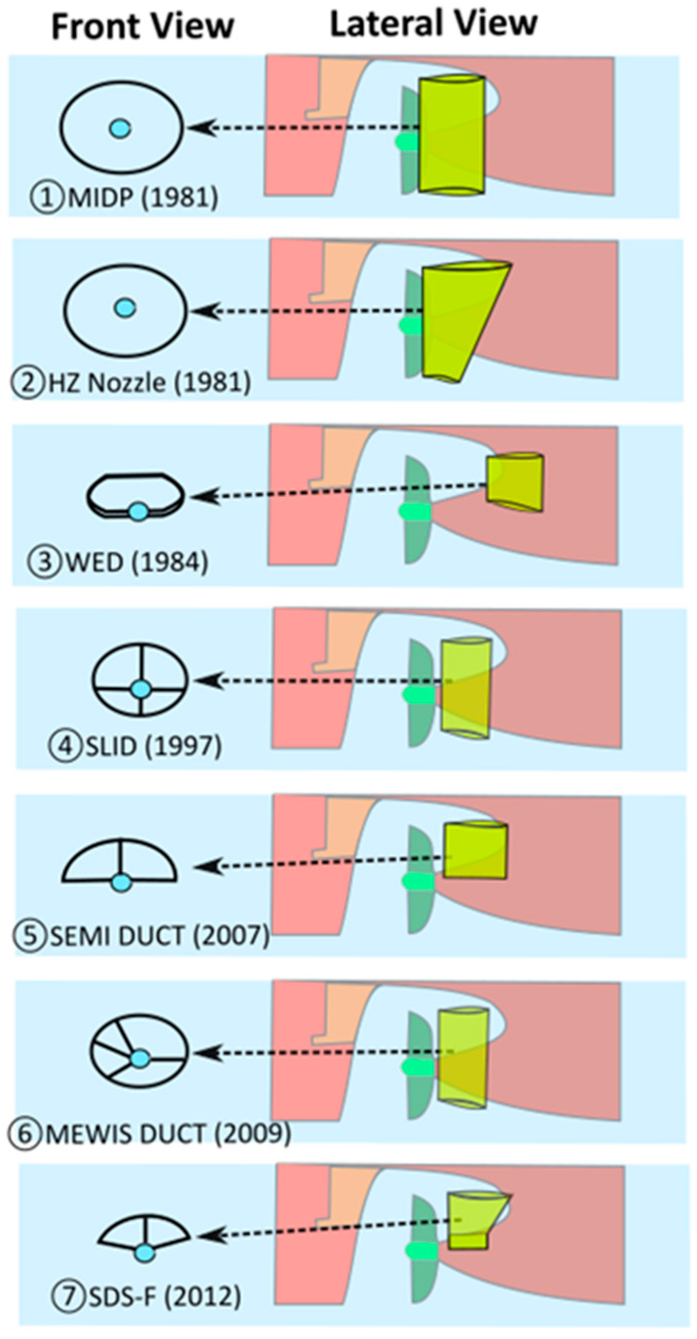
Figure 1. Pre-swirl ducts over the years.
Mewis Ship Hydrodynamics has developed the well-known PSD in cooperation with Becker Marine Systems GmbH & Co. Additionally, Becker Marine Systems GmbH & Co. has patented a twisted fins system, whose nozzle ring is significantly smaller than that of the Mewis duct® and has a flat profile with a much lower drag [11].
The idea of Van Lammeren was considered in 1984 by Schneekluth to invent the Schneekluth Wake Equalizing Duct (WED), and in 1997 by Sumitomo Heavy Industries to build the Sumitomo Integrated Lammeren Duct (SILD).
The WED consists of two half-ring ducts, which are fitted to the hull in front of the propeller. The SILD is geometrically similar to the MIDP, but instead of being fitted directly to the hull, it is mounted using struts and located eccentrically for the propeller shaft.
In 2007 a Semi-Circular Duct was launched by IHI Marine United, very similar to the SILD but with a semi-circular design instead of a circular one. F. Mewis and H. Peters in 1986 proposed a novel fin system (SVA Fin system) to decrease the rotational losses [14]. Daewoo Shipbuilding & Marine Engineering (DSME) has been manufacturing for decades Pre-Swirl Stator fins asymmetric and symmetric (Lee et al. [15]). The background history of Mewis duct® and Becker twisted fins® by Becker Marine Systems GmbH & Co. (Hamburg, Germany) is shown in Figure 2.
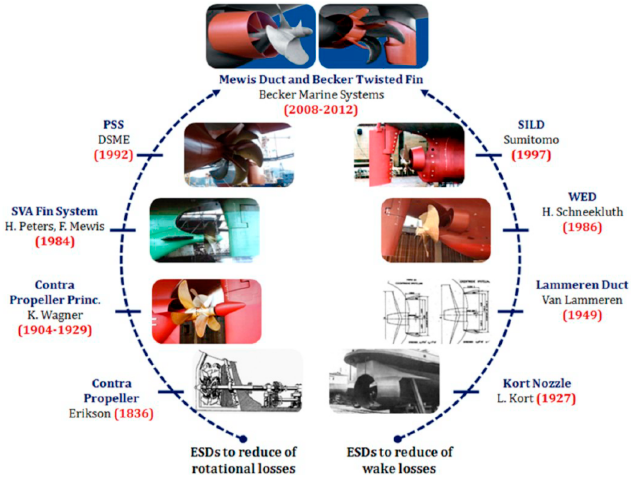
Figure 2. History of Mewis duct® and Becker twisted fins® (Becker Marine Systems GmbH & Co. KG, Hamburg, Germany) [16].
Several authors [17][18][19][20][21][22][23] have performed simulations over the JAPAN Bulk Carrier (JBC), while other researchers [24][25] have considered the general cargo carrier REGAL. Both these vessels have a U-shape hull that tends to have a relatively steep transition from the mid-ship section to the stern, and commonly suffer from the intensive bilge vortex in the wake field. Such non-uniform axial distribution of velocities generates axial losses in the flow, whose recovery is ensured by fitting a circular duct behind the stern.
Terwisga [26] tried to define the working principles of the PSDs. He first explained that to obtain a power reduction, there are essentially two options:
-
Enhancing the propeller efficiency.
-
Improving the propeller-hull interaction, to require less thrust.
Given the amount of literature about different ESDs, some researchers have been engaged in a sort of design challenge. Nowruzi et al. [16] highlighted the need for a sort of guidelines to design the geometrical parameters and position of the pre-swirl ducts independent of the inflow pattern.
2.3. Post-Swirl
The concept of a device located after a propeller assumes that the slipstream of a propeller has an annular shape. As contraction effects tend to leave an area of stagnant flow behind the hub, it is worthwhile to fill this area with a body. The post-swirl devices include several examples such as:
-
Propeller Boss Cap Fins (PBCF). The PBCF (Figure 3), originally developed by Mitsui OSK, consists of small fins attached to the boss cap fixed to the propeller. It recovers energy from the propeller hub vortex. The number of fins is the same as that of the propeller blades [27]. A study by Katayama et al. [28] included a list of typical profiles of general propeller caps and a specific propeller cap (contraction type) with fins (namely called ECO-Cap). The authors found an increase in the total efficiency due to the ECO-Cap was predicted by CFD and confirmed by the model test. The ECO-Cap prevents, as expected, the generation of the hub vortex. It is expected that this phenomenon makes the hub vortex weak, providing an overall improvement of about 1.28%. The PBCF performances are usually evaluated at the model scale.
-
Grim Vane Wheel. The Grime Vane Wheel is a freely rotating device located behind the propeller, and it is composed of a turbine section inside the propeller slipstream and a propeller section (vane tips) outside the propeller slipstream. It is even called “Grimsches Leitrad” and was first developed by Otto Grim. Its main function is to extract energy from the propeller slipstream in the turbine portion and convert this energy into additional thrust in the propeller portion. The vane wheel became unpopular after several reports of mechanical failures, most notably for the cruise ship Queen Elizabeth 2 in 1986. A joint project between Hyundai Heavy Industries (HHI) and Det Norske Veritas (DNV) restored its reputation by developing a modern vane wheel supported on the rudder [27][30].
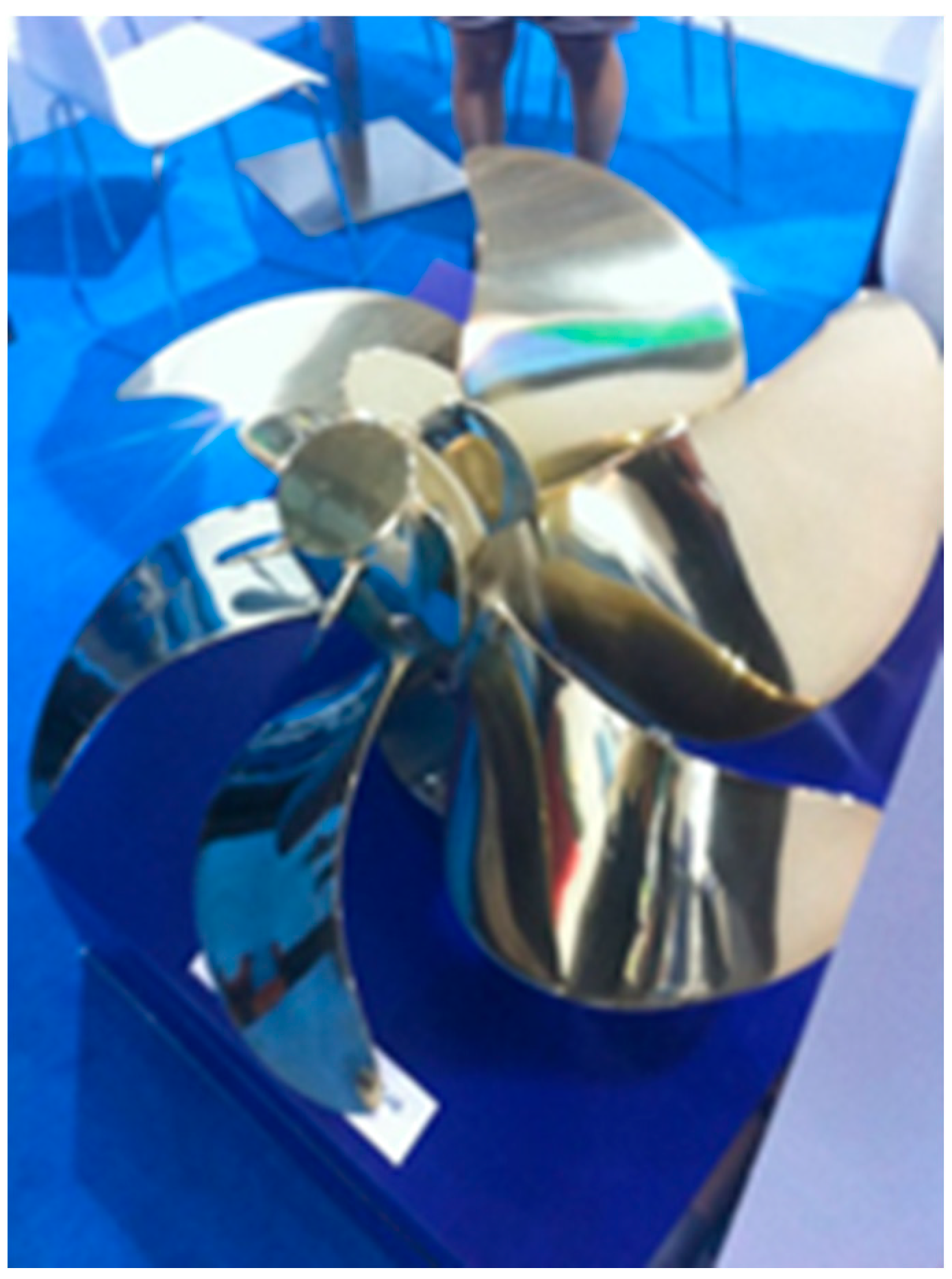
Figure 3. Post-swirl devices: PBCF [5].
This entry is adapted from the peer-reviewed paper 10.3390/jmse10050574
References
- Hasselaar, T.W.; Xing-Kaeding, Y. Evaluation of an energy-saving device via validation speed/power trials and full-scale CFD investigation. Int. Shipbuild. Prog. 2017, 63, 169–195.
- RESOLUTION MEPC.333(76), ANNEX 7; Guidelines on the Method of Calculation of the Attained Energy Efficiency Existing Ship Index (EEXI). IMO: London, UK, 2021.
- BIMCO. 2020. Available online: https://bi-cd02.bimco.org/news/environment-protection/20200219-eexi-proposal-to-imo (accessed on 21 December 2021).
- Rutherford, D.; Mao, X.; Comer, B. Potential CO2 Reductions under the Energy Efficiency Existing Ship Index; International Council on Clean Transportation (ICCT): Washington, DC, USA, 2020.
- Carlton, J.S. Marine Propellers and Propulsion, 4th ed.; Butterworth-Heinemann: Oxford, UK, 2019.
- Terwisga, T. On the working principles of Energy Saving Devices. In Proceedings of the Third International Symposium on Marine Propulsors (SMP’13), Launceston, Australia, 5–8 May 2013.
- Prins, H.J.; Flikkema, M.B.; Schuiling, B.; Kaeding, Y.X.; Voermans, A.A.M.; Müller, M.; Coache, S.; Hasselaar, T.W.F.; Paboeuf, S. Green retrofitting through optimisation of hull-propulsion interaction—GRIP. In Proceedings of the 6th Transport Research Arena (TRA), Warsaw, Poland, 18–21 April 2016.
- Flikkema, M.; Goorden, B.; Cervicato, C.; Verhulst, M.; Schuiling, B.; Janse, G.; Voermans, A.; de Bot, B.; Terwisga, T.; Portolano, A.; et al. Design and demonstration of an Energy Saving Device for a ship with controllable pitch propeller. In Proceedings of the 8th Transport Research Arena (TRA), Helsinki, Finland, 27–30 April 2020.
- Dang, J.; Chen, H.; Guoxiang, D.; van der Ploeg, A.; Hallmann, R.; Mauro, F. An exploratory study on the working principles of Energy Saving Devices (ESDs). In Proceedings of the Symposium on Green Ship Technology (Greenship’11), Wuxi, China, 10–11 October 2011.
- Nadery, A.; Ghassemi, H.; Chybowski, L. The effect of the PSS configuration on the hydrodynamic performance of the KP505 propeller behind the KCS. Ocean Eng. 2021, 234, 109310.
- The Maritime Executive. Available online: https://www.maritime-executive.com/corporate/New-EnergySaving-Device-The-Becker-Twisted-Fin (accessed on 16 July 2020).
- Force Technology. Available online: https://forcetechnology.com/en/cases/how-a-fin-and-a-duct-save-fuel (accessed on 19 July 2020).
- Schuiling, B.; van Terwisga, T. Hydrodynamic working principles of Energy Saving Devices in ship propulsion systems. Int. Shipbuild. Prog. 2016, 63, 255–290.
- Mewis, F.; Peters, H.E. Power savings through a novel fin system. In Proceedings of the 15th SMSSH Conference, Varna, Bulgaria, 6–11 October 1986.
- Lee, J.T.; Kim, M.C.; Suh, J.C.; Kim, S.H.; Choi, J.K. Development of a Pre Swirl Stator Propeller System for Improvement of Propulsion Efficiency: A Symmetric Stator Propulsion System; Society of Naval Architects of Korea (SNAK): Busan, Korea, 1992.
- Nowruzi, H.; Najafi, A. An experimental and CFD study on the effects of different pre-swirl ducts on propulsion performance of series 60 ship. Ocean Eng. 2019, 173, 491–509.
- Maasch, M.; Mizzi, K.; Atlar, M.; Fitzsimmons, P.; Turan, O. A generic wake analysis tool and its application to the Japan Bulk Carrier test case. Ocean Eng. 2019, 171, 575–589.
- Furcas, F.; Vernengo, G.; Villa, D.; Gaggero, S. Desing of Wake Equalizing Ducts using RANSE-based SBDO. Appl. Ocean Res. 2020, 97, 102087.
- Bekhit, A.S. Numerical simulation of the ship self-propulsion prediction using body force method and fully discretized propeller model. IOP Conf. Ser. Mater. Sci. Eng. 2018, 400, 042004.
- Windén, B.; Huang, Z.; Kawamura, T. Comparative self-propulsion simulations of the JBC bulk carrier. In Proceedings of the Japan Society of Naval Architects and Marine Engineers (JASNAOE) Spring Meeting, Kobe, Japan, 25 May 2015.
- Andersson, J.; Hyensjö, M.; Eslamdoost, A.; Bensow, R. CFD simulations of the Japan Bulk Carrier Test case. In Proceedings of the Numerical Towing Tank Symposium, Cortona, Italy, 27–29 September 2015.
- Korkmaz, K.B. CFD Predictions of Resistance and Propulsion for the Japan Bulk Carrier (JBC) with and without an Energy Saving Device. Master’s Thesis, Chalmers University of Technology, Gothenburg, Sweden, 2015.
- Bakica, A.; Vladimir, N.; Ančić, I. Improving ship energy efficiency performance by energy-saving devices. In Proceedings of the International Conference on Smart & Green Technology for the Future of Marine Industries (SMATECH 2019), Glasgow, UK, 11–12 July 2019.
- Jasak, H.; Vukcevic, V.; Gatin, I.; Lalovic, I. CFD validation and grid sensitivity studies of full-scale ship self-propulsion. Int. J. Nav. Archit. Ocean Eng. 2018, 11, 33–43.
- Vukcevic, V.; Jasak, H.; Gatin, I.; Uroic, T. Ship scale self-propulsion CFD simulation results compared to sea trials measurements. In Proceedings of the International Conference on Computational Methods in Marine Engineering, Nantes, France, 15–17 May 2017.
- Olsen, A.S. Energy coefficients for a propeller series. Ocean Eng. 2004, 31, 401–416.
- Hochkirk, K.; Bertram, V. Options for fuel-saving for ships. In Proceedings of the Mare Forum: Maritime Transportation of Energy, Houston, TX, USA, 19 February 2010.
- Katayama, K.; Yoshihisa, O.; Okazaki, A. Optimization of the propeller with ECO-cap by CFD. In Proceedings of the International Symposium on Marine Propulsors (SMP’15), Austin, TX, USA, 31 May–4 June 2015.
- Shiffbau-Versuchsanstalt Postdam (SVA). Available online: https://www.sva-potsdam.de/en/energy-saving-devices/ (accessed on 22 March 2022).
- Safety4Sea. Available online: https://safety4sea.com/hhi-and-dnv-gl-take-a-fresh-look-at-grims-vane-wheel/?__cf_chl_jschl_tk__ (accessed on 25 July 2020).
This entry is offline, you can click here to edit this entry!